Transcription
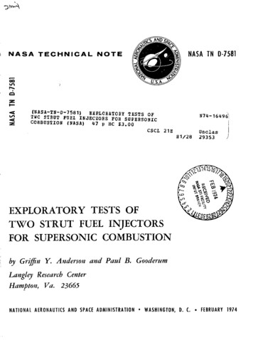
ANUNASA TECHNICALL-MNASA TN D-7581NOTEI(NASA-TN-D-7581) EXPLEATORY TESTS OFTWC STRUT FUEL INJECTOS FOR SUPERSONICCOMBUSTION(NASA)N74-16496)47 p HC 3.00CSCL 21EH1/28Unclas293531314 1SEXPLORATORY TESTS OFTWO STRUT FUEL INJECTORSFOR SUPERSONIC COMBUSTIONby Griffin Y. Anderson and Paul B. GooderumLangley Research CenterHampton, Va. 23665NATIONAL AERONAUTICS AND SPACE ADMINISTRATION * WASHINGTON, D. C. * FEBRUARY 1974
2. Government Accession No.1. Report No.3. Recipient's Catalog No.NASA TN D-75815. Report Date4. Title and SubtitleEXPLORATORY TESTS OF TWO STRUT FUEL INJECTORSFebruary 19746. Performing Organization CodeFOR SUPERSONIC COMBUSTION8. Performing Organization Report No.7. Author(s)L-9428Griffin Y. Anderson and Paul B. Gooderum10. Work Unit No.9. Performing Organization Name and Address501-04-03-02NASA Langley Research CenterHampton, Va. 2366511. Contract or Grant No.13. Type of Report and Period Covered12. Sponsoring Agency Name and AddressTechnical NoteNational Aeronautics and Space AdministrationWashington, D.C. 2054614. Sponsoring Agency Code15. Supplementary Notes16. AbstractResults of supersonic mixing and combustion tests performed with two simple strutinjector configurations, one with parallel injectors and one with perpendicular injectors, arepresented and analyzed. Good agreement is obtained between static pressure measured on theduct wall downstream of the strut injectors and distributions obtained from one-dimensionalcalculations. Measured duct heat load agrees with results of the one-dimensional calculationsfor moderate amounts of reaction but is underestimated when large separated regions occurnear the injection location. For the parallel injection strut, good agreement is obtainedbetween the shape of the injected fuel distribution inferred from gas sample measurements atthe duct exit and the distribution calculated with a multiple-jet mixing theory. The overallfraction of injected fuel reacted in the multiple-jet calculation closely matches the amount offuel reaction necessary to match static pressure with the one-dimensional calculation. Gassample measurements with the perpendicular injection strut also give results consistent withthe amount of fuel reaction in the one-dimensional calculation.17. Key Words (Suggested by Author(s))18. Distribution StatementUnclassified - UnlimitedSupersonic combustionScramjetFuel injectorsSTAR Category 2819. Security Classif. (of this report)Unclassified20. Security Classif. (of this page)Unclassified21. No. of Pages-4 -For sale by the National Technical Information Service, Springfield, Virginia 2215122. Price* 3.00
EXPLORATORY TESTS OF TWO STRUT FUEL INJECTORSFOR SUPERSONIC COMBUSTIONBy Griffin Y. Anderson and Paul B. GooderumLangley Research CenterSUMMARYResults of supersonic mixing and combustion tests performed with two simple strutinjector configurations, one with parallel injectors and one with perpendicular injectors,are presented and analyzed. Good agreement is obtained between static pressure measured on the duct wall downstream of the strut injectors and distributions obtained fromMeasured duct heat load agrees with results of the onedimensional calculations for moderate amounts of reaction but is underestimated whenlarge separated regions occur near the injection location. For the parallel injectionone-dimensional calculations.strut, good agreement is obtained between the shape of the injected fuel distributioninferred from gas sample measurements at the duct exit and the distribution calculatedwith a multiple-jet mixing theory. The overall fraction of injected fuel reacted in themultiple-jet calculation closely matches the amount of fuel reaction necessary to matchstatic pressure with the one-dimensional calculation. Gas sample measurements withthe perpendicular injection strut also give results consistent with the amount of fuel reaction in the one-dimensional calculation.INTRODUCTIONThe feasibility and performance potential of the supersonic combustion ramjet(scramjet) engine for flight at hypersonic speeds was firmly established by a number ofsuccessful research-scale engine demonstrations in the 1960's. (See ref. 1 for discussion.) The particular configurations and internal aerothermodynamic design featuresthat will eventually evolve for practical flight applications are only now beginning toThe importance of carefully integrating the engine with the vehicle and ofreducing engine cooling requirements is emphasized by results in references 2 and 3.Low engine cooling load is necessary to maintain an engine fuel cooling margin that canemerge.be used for active cooling of parts of the vehicle other than the engine. Since the comhibstnr can account for 60 percent to 80 percent of the engine cooling requirement, reducedcooling is a first-order consideration in supersonic combustor design.I
Most of the research-scale engine work relied entirely on flush wall fuel injectorsin their combustor designs. (See ref. 1.) As the combustor length is a function of thecombustor height at the point of fuel injection, instream fuel injection from struts in multiple planes provides a direct means for reducing the combustor length and coolingrequirement for full-scale engines. Reference 4 reports results of tests with a largecircular supersonic combustor (46-cm diameter) in which various strut fuel injectordesigns and arrangements were explored. However, in that study the struts are intendedonly as fuel injectors; strut blockage and drag are considered to be performance penalties. The integrated scramjet engine concept discussed in references 2, 3, and 5 is basedon an inlet which employs multiple swept struts with carefully designed upstream contoursto perform the bulk of the inlet compression process. In fact, as pointed out in reference 5, the struts may block about 60 percent of the flow cross-sectional area in thethroat (minimum cross-sectional area) region of the inlet. Although this blockage produces drag, the drag is a necessary part of the inlet compression process and is not afuel injector loss.Fuel injectors can then be designed into the aft part of the inlet compression struts to achieve a short combustor. As pointed out in reference 5, injectionboth parallel to and perpendicular to the oncoming flow direction may be desirable toachieve the best performance from a particular combustor geometry at different flightspeeds.The principal objective of the present study is to determine the flow fields producedby simple strut injectors and attempt to model those flow fields by comparison of test datawith results calculated by using a one-dimensional analysis and empirical mixing models.The emphasis in the experimental design is to achieve representative strut injector flowfields (rather than model a particular engine configuration) with minimum hardware complexity and maximum use of existing supersonic combustor hardware. For this reason,the injector struts are oriented perpendicular to the flow direction (without leading-edgesweep).Although this orientation greatly simplifies the experimental design, it must berecognized that cross flow and other effects will occur with swept injection struts whichmay be important in an engine design; further experiments will be required to assess theimportance of the effects of sweep on the mixing reacting flow field generated by strutinjection.Tests are conducted at conditions simulating Mach 7 flight with parallel and perpendicular injection struts in three test configurations: free jet, short duct, and long duct.The free-jet tests are intended to determine the adequacy of the mechanical and thermaldesign of the struts, give a qualitative picture of the flow field, and allow some cut-andtry modification of the injector port designs. The short-duct tests are used to verifystarting of the ducted configuration. The long-duct tests are designed to provide enoughmeasurements to determine combustion performance. Wall static pressure and duct2
cooling requirements are measured along with duct exit probe measurements of pitotpressure and gas composition.SYMBOLSc1,c 2correlation parameters (see eq. 2)dinjector diameterfburner fuel to oxidizer ratio,Iburner free oxygen parameter,Fuel flowAir oxygen flow(Oxygen flow) (0.0823); forFuel flowI 1, test gashas same free oxygen content as air (20.95 percent by volume)MMach numberppressurePaambient pressureQduct heat loadQoduct heat load with no fuel injectionqrratio of jet pressure to stream dynamic pressuresjet spacingTtemperaturexdistance measured in flow directionxPlength for complete reaction of injected fuelydistance measured across long dimension of duct from the duct center liney'shifted coordinate defined as the distance measured across long dimension ofduct from the nearest jet center line3
zdistance measured across short dimension of duct from center linealocal mass fraction of injected fuelSbulkbulk mass fraction of injected fuel,wh Wj(3short duct angular misalinement (see figs. 9 and 10)77ccombustion efficiency,0injected equivalence ratioOrreacted equivalence ratioWmass flow rateOrSubscripts:educt exithburnerjinjectorTstagnation2pitotANALYSISThe ability to calculate the wall pressure distribution and heat transfer that occurin a supersonic combustor is important for the evaluation of any proposed scramjet enginedesign. The general problem is very complex, and involves supersonicflow, fuel injection, turbulent mixing, and combustion; as a first step, a simplified analysisis desirable.One approach to developing a simplified analysis is described in the followingparagraphs.The theory is one dimensional and includes the effects of area change, wallfriction, heattransfer, fuel injection and reaction, but does not includeshock waves, flow separation,or chemical kinetic effects.4
One-Dimensional Flow ModelA schematic of the supersonic combustion flow model used for calculations in thisreport is shown in figure 1.The analysis is based on the one-dimensional conservationequations for mass, momentum, and energy.Independent input parameters to the analysisare the geometry of the combustor, entering flow conditions, fuel injection distribution,fuel reaction distribution, wall skin-friction coefficient, and wall temperature as indicatedWith these parameters given, the conservation equations are used to calculatethe flow properties along the combustor, stepwise, in a marching procedure starting fromthe combustor entrance. Thus, the calculation provides flow properties and wall heattransfer distributions with axial distance along the combustor. The computer programin figure 1.(LAR-11041) which is used to make the calculations is available from COSMIC (Universityof Georgia).Gas model.- Gas properties are calculated in the computer program by using tabulated real-gas thermodynamic properties and allowing for up to nine chemical species(H 2 0, 02, H 2 , N 2 , Ar, O, H, NO, and OH).The amount of each species present is deter-mined from a chemical equilibrium calculation which has a partial reaction feature.Equilibrium chemical composition is calculated for the combustion products of the testgas and reacted fuel at a given axial location.Any fuel injected but remaining unreactedat that location is kept in thermal equilibrium with these combustion products.Fuel reaction distribution.- Specification of an appropriate fuel reaction distributionwith length for a given combustor geometry and fuel injector design is the key problem inIf the static temperature and pressure of the flow are high so thatusing the analysis.local chemical equilibrium can be assumed, then the amount of fuel reaction with lengthis the same as the amount of accomplished fuel mixing with length.This approach is usedsuccessfully in references 5 and 6 to model supersonic combustion flow fields with parallel and perpendicular fuel injection.In reference 6 parallel injection with a single jet in a coaxial supersonic mixing andcombustion experiment is found to produce a nearly linear variation of accomplished mixing and combustion with length from the injector.r77wherexfestimatedThus,xx(1)is defined as the length for complete mixing or reaction.frum mixingThe value of xtheoU-y - u h as the analysis described in reference 7.isFor such anestimate an appropriate eddy viscosity model is required. The eddy viscosity modeldeveloped in reference 8 with a value of empirical constant in the model equal to 0.01 isused successfully in reference 6 to correlate both reacting and nonreacting data.Refer5
ence 9 presents an analysis for multiple parallel jets with merging mixing patterns, butempirical turbulent transport rates or eddy viscosity models have not been developed forthis analysis.Analyses (equivalent to those of refs. 7 and 9 for parallel injection) are not available for perpendicular injection flow fields. The study in reference 10 provides a directempirical approach to representing the accomplished mixing in perpendicular injectionflow fields.Reference 10 reports extensive composition profile data for multijet perpendicular wall injection of hydrogen in air without reaction. Integrations of the profiledata were used to determine the amount of accomplished mixing defined at any downstreamlocation as the fraction of injected fuel that would react if complete reaction occurredwithout further mixing. The correlations of these results presented in reference 10 wereused in reference 5 to determine a schedule of reaction with distance from the injectionpoint shown in table I. This schedule of reaction was used successfully in reference 5 tomodel wall static-pressure data from a supersonic combustion experiment with perpendicular wall injection. The value of length for complete mixing x2 is calculated fromx cld(qr) c 2(2)whered is the injector diameter and cl and c 2 are parameters from the correlations of reference 10 that depend on injector spacing.TABLE I.- DIMENSIONLESS REACTION DISTRIBUTIONFOR PERPENDICULAR INJECTION00.
strut, good agreement is obtained between the shape of the injected fuel distribution inferred from gas sample measurements at the duct exit and the distribution calculated with a multiple-jet mixing theory. The overall fraction of injected fuel reacted in the multiple-jet calculation closely matches the amount of fuel reaction necessary to match static pressure with the one-dimensional .
