Transcription
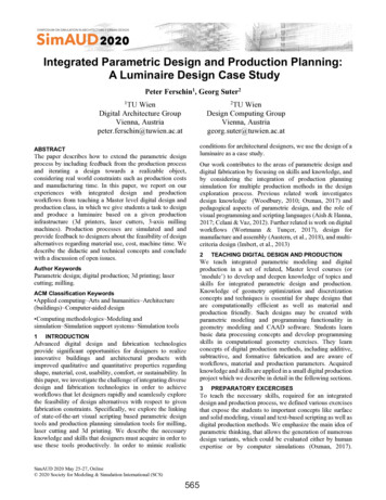
Integrated Parametric Design and Production Planning:A Luminaire Design Case StudyPeter Ferschin1, Georg Suter212TU WienDigital Architecture GroupVienna, Austriapeter.ferschin@tuwien.ac.atTU WienDesign Computing GroupVienna, Austriageorg.suter@tuwien.ac.atABSTRACTThe paper describes how to extend the parametric designprocess by including feedback from the production processand iterating a design towards a realizable object,considering real world constraints such as production costsand manufacturing time. In this paper, we report on ourexperiences with integrated design and productionworkflows from teaching a Master level digital design andproduction class, in which we give students a task to designand produce a luminaire based on a given productioninfrastructure (3d printers, laser cutters, 3-axis millingmachines). Production processes are simulated and andprovide feedback to designers about the feasibility of designalternatives regarding material use, cost, machine time. Wedescribe the didactic and technical concepts and concludewith a discussion of open issues.Author KeywordsParametric design; digital production; 3d printing; lasercutting; milling.ACM Classification Keywords Applied computing Arts and humanities Architecture(buildings) Computer-aided design Computing methodologies Modeling andsimulation Simulation support systems Simulation tools1INTRODUCTIONAdvanced digital design and fabrication technologiesprovide significant opportunities for designers to realizeinnovative buildings and architectural products withimproved qualitative and quantitative properties regardingshape, material, cost, usability, comfort, or sustainability. Inthis paper, we investigate the challenge of integrating diversedesign and fabrication technologies in order to achieveworkflows that let designers rapidly and seamlessly explorethe feasibility of design alternatives with respect to givenfabrication constraints. Specifically, we explore the linkingof state-of-the-art visual scripting based parametric designtools and production planning simulation tools for milling,laser cutting and 3d printing. We describe the necessaryknowledge and skills that designers must acquire in order touse these tools productively. In order to mimic realisticSimAUD 2020 May 25-27, Online 2020 Society for Modeling & Simulation International (SCS)565conditions for architectural designers, we use the design of aluminaire as a case study.Our work contributes to the areas of parametric design anddigital fabrication by focusing on skills and knowledge, andby considering the integration of production planningsimulation for multiple production methods in the designexploration process. Previous related work investigatesdesign knowledge (Woodbury, 2010; Oxman, 2017) andpedagogical aspects of parametric design, and the role ofvisual programming and scripting languages (Aish & Hanna,2017; Celani & Vaz, 2012). Further related is work on digitalworkflows (Wortmann & Tunçer, 2017), design formanufacture and assembly (Austern, et al., 2018), and multicriteria design (Imbert, et al., 2013)2TEACHING DIGITAL DESIGN AND PRODUCTIONWe teach integrated parametric modeling and digitalproduction in a set of related, Master level courses (or‘module’) to develop and deepen knowledge of topics andskills for integrated parametric design and production.Knowledge of geometry optimization and discretizationconcepts and techniques is essential for shape designs thatare computationally efficient as well as material andproduction friendly. Such designs may be created withparametric modeling and programming functionality ingeometry modeling and CAAD software. Students learnbasic data processing concepts and develop programmingskills in computational geometry exercises. They learnconcepts of digital production methods, including additive,subtractive, and formative fabrication and are aware ofworkflows, material and production parameters. Acquiredknowledge and skills are applied in a small digital productionproject which we describe in detail in the following sections.3PREPARATORY EXCERCISESTo teach the necessary skills, required for an integrateddesign and production process, we defined various exercisesthat expose the students to important concepts like surfaceand solid modeling, visual and text-based scripting as well asdigital production methods. We emphasize the main idea ofparametric thinking, that allows the generation of numerousdesign variants, which could be evaluated either by humanexpertise or by computer simulations (Oxman, 2017).
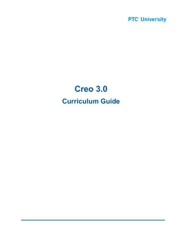
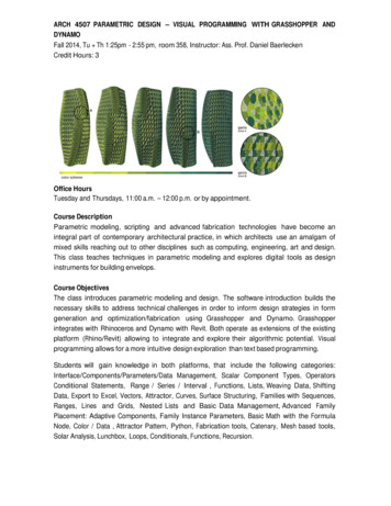
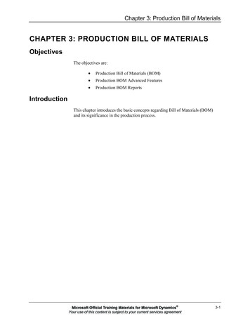
Important is the concept of identifying key design parametersas independent and dependent variables.3.1 Surface ModelingNon-uniform rational B-splines (NURBS) modeling is aquasi-industry standard geometric modeling method forcurves and surfaces which is widely used in the developmentof innovative designs, including industrial design, arts andcrafts, and architectural design. Its popularity is due to easeof use in rapidly creating and modifying complex free-formshapes based on intuitive parameters, such as control pointsand weights. Continuity (or smoothness) is a key qualitycriterion for free-form shapes. Analysis methods that areprovided by geometric design tools include curvature graphswhich let designers assess the smoothness of transitionsbetween curve or surface segments. We use the NURBSmodeling functionality in Rhino to study surface modeling.3.2 Visual ScriptingVisual scripting interfaces facilitate graphical rather thantext-based program definition. Thus they appear useful fordesigners who tend not to be expert programmers. Examplesof visual scripting environments for computer-aidedgeometric and architectural design include RhinoGrasshopper and Revit Dynamo. Visual scripting is usuallybased on the dataflow programming method. A programconsists of a directed, acyclic graph where the nodes processdata and edges represent data flow between nodes. Each nodeaccepts input data, processes the data, and sends output torelated nodes. The graph is automatically evaluated wheninput data are modified. This is beneficial for design taskswhere it is necessary to rapidly modify an evolving designby varying input parameters. We use the Rhino Grasshopperenvironment for visual scripting.3.3 Python ScriptingWe additionally expose students to text-based scripting, inparticular with Python scripting in Rhino as well as inGrasshopper. We choose Python as a language, as it is themost common scripting environment in 3D designapplications. We introduce a small subset of the languagePython, geometry creation in Rhino and how scripts can beintegrated into the Grasshopper environment to extend thepredefined functionalities. Each lecture is accompanied bysmall exercises to verify that the provided scripts of thelectures can be applied with small adaptations. The firstlecture is focused on parametric two-dimensional curves,simple 3d solids and extruded geometry from curves. Toteach first steps in programming, we implemented amodified version of a Turtlegraphics Python library forRhino. The exercise for the students consists of writing theirfirst name as a parametric function, additionally supportingdifferent graphical styles (Figure 1). The implementationshould define a Grasshopper python component, with a listof polylines as output parameter that can be manipulatedfurther (e.g. by extrusion).566Figure 1. Parametric first name – Lena Roth, 2019The second lecture focuses on constructing NURBS surfacesfrom NURBS curves and by defining parametricmathematical functions that specify design parameters andimplement surface meshes with adaptable resolutions. As anexercise, students have to define suitable mathematicalformulas and design parameters to create parametric disheswith design variations as mesh structures implemented asPython components in Grasshopper.
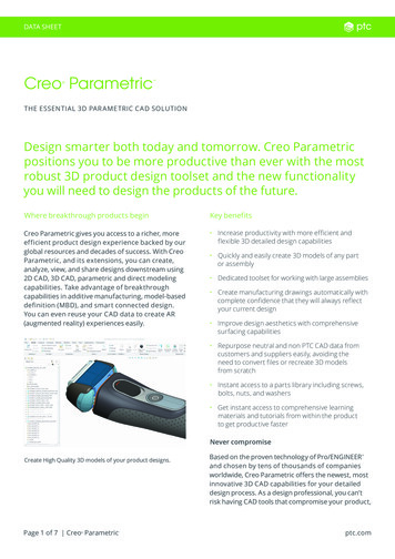
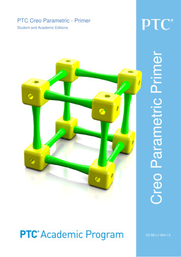
3.4 3D PrintingIn a separate lecture (“Digital Production”) we explain theprinciples and possibilities of 3d printing and whatrequirements for geometric models need to be considered(e.g. solid geometry, closed volumes, consistent normalvectors). As an exercise, students have to prepare a terrainmodel for printing. For the simulation of the printing processUltimaker Cura is utilized, parameters that influence thespeed and quality of the printing process are explained.Figure 2. Parametric dishes – Lena Roth, 2019The third lecture explains how parametrically definedmeshes can be converted into buildable structures bygenerating solid elements at vertices, edges or faces of amesh. The parametric dish functions of the previous exercisehave to be converted into buildable structures.Figure 4. Preparing a terrain for 3d printing – Lena Roth, 20193.5 CNC CuttingIn the next step, various CNC cutting strategies areintroduced (e.g. laser cutting, waterjet cutting). As anexercise, the same terrain needs to be prepared to begenerated as layers on a laser cutter. An additional exerciseintroduces the task of designing a parametric Kirigami (theart of paper cutting and folding) layout. To simulate thecutting process the tool VisiCut is used to check the layoutfor the laser cutter as well as to estimate the cutting time.Figure 3. Parametric dish constructions – Lena Roth, 2019567
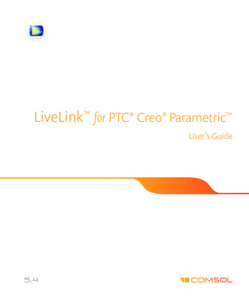
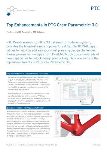
to the stock material is visually inspected. Additionally, thetime required for milling is evaluated.Figure 7. Preparing a terrain for 3-axis milling – Lena Roth, 2019Figure 5. Preparing a terrain for laser cutting – Lena Roth, 2019Figure 6. Parametric Kirigami design – Mihael Barada, 20193.6 CNC MillingNext, the principles of CNC milling are introduced and aPython library for generating CNC code is provided to thestudents. The terrain has to be prepared for a 3-axis millingmachine. An additional exercise – to generate parametricmilling patterns – has to be implemented as a Pythoncomponent in Grasshopper. For the simulation of the 3-axismilling process the software Camotics is used. As the millingpaths are generated by the students with Python, it isimportant to check for possible errors that could damagetheir work piece or even the milling machine. This is doneby evaluating the milling paths in Camotics and verifyingthat no collisions with the milling machine will happen.Furthermore the plausibility of the milling paths in relation568Figure 8. Parametric milling patterns– Lena Roth, 20194PARAMETRICPRODUCTIONLUMINAIREDESIGNANDWe illustrate the parametric design and productionworkflows outlined above with an example project.4.1 Design BriefThe design task involves the design of a luminaire for aspecific activity, such as dining or reading, and for a specificroom, such as dining room or office. To ensure diversity inluminaire designs, these functional requirements were
defined by the students. Designs must further meet specificrequirements regarding lamps, screens, and connectors. Forexample, lamps should be low cost, screens made of acrylicglass, and connectors of synthetic material. Moreover,milling, laser cutting, and 3d printing methods are to be usedin production. Production constraints must be considered.For example, the production of luminaire parts by 3d printingshould not exceed 4 hours, and the total available volume isat most 11cm x 11cm x 11cm.4.2 ScheduleProjects need to be completed over a period of 9 weeks. Afteran initial concept design phase (Week 1), subsequentiterations focus on the development of the parametric model(Week 3), production planning (Week 5), production (Week7), assembly (Week 8), and final presentation (Week 9).Feedback is provided in review sessions after Week 1, Week3, Week 5 and Week 9.Figure 10. Printing simulation (2:01 hours), Luminaire “Flora” –Robert Zanona, Christoph Rössler, Erdinc Özcaliskan, 20195.2 Simulating the Laser Cutting processUsing VisiCut, the layout of the cutting parts is verified,additionally an estimated cutting time is calculated. The timefor working on the laser cutter is limited to 1h per group, soa cutting time less than 45min should be achieved. 15min isreserved for machine setup.Figure 9. Parametric design, Luminaire “Flora” – Robert Zanona,Christoph Rössler, Erdinc Özcaliskan, 20195SIMULATION AT THE DESIGN AND PRODUCTIONPROCESSLuminaire designs are generated by a parametric model,which is implemented as a combination of manual modelingsteps, visual scripting (Grasshopper) and text scriptingcomponents (Python). An important part of the designstrategy is to decide which components of the luminaire arerealized with what kind of production technology. Studentsneed to determine design parameters that influenceproduction time. Through evaluation of design variants, thebest parameter sets need to be identified that achieve theintended design while fulfilling production constraints. Tofacilitate data sharing between parametric design andproduction planning simulation, files in CNC data formatsare automatically created by parametric models.5.1 Simulating the 3D Printing processFor the parts that need to be 3d printed, Ultimaker Cura isused to verify the geometric consistency and the requiredprinting time. The time constraint was set to 4h printing timeper project.569Figure 11. Laser cutting simulation, Luminaire “Onion” – IgorMilekic, Fabijan Farkas, Annabella Lintl, 20195.3 Simulating the Milling processUsing Camotics, the simulation of the milling path is used toensure that no collision with the tool and the milling machineoccurs and the milling path is inside the stock dimensions(59cm x 99cm). The tool is fixed with a 6mm ballpoint cutterand tool changes are not allowed. Additionally, thecalculation of the milling time is verified with the proposedconstraints (45min milling, 15 min preparation).
beginning of each production step. The final step involvesmanual assembly of the luminaire from its parts. Teams tracksteps in the assembly and keep time records for each step.Issues encountered during assembly are documented.Figure 12. Milling simulation, Luminaire “Flora” – RobertZanona, Christoph Rössler, Erdinc Özcaliskan, 20195.4 Light Simulation of the Lamp DesignTo evaluate visual design performance, variants are renderedphoto-realistically to identify suitable design parameters forthe intended lighting effect.Figure 14. Milling, Luminaire “Flora” – Robert Zanona,Christoph Rössler, Erdinc Özcaliskan, 2019Figure 15. 3d printing, Luminaire “Flora” – Robert Zanona,Christoph Rössler, Erdinc Özcaliskan, 2019Figure 13. Light simulation, Luminaire “Shingle Dingle” –Ekaterina Ermishkina, Clemens Horvath, 20206PRODUCTION AND ASSEMBLYLuminaire parts are fabricated in a workshop which isequipped with 2 3-axis milling machines (Step Four Precise1000U), 2 laser cutters (Trotec Speedy 500), and 4 3dprinters (Renkforce RF100 v2). Allowed maximumproduction times are, respectively, 45 minutes for engravingof screen faces by milling, 45 minutes for cutting screen partsby laser cutting, and 4 hours for creating connector parts by3d printers. Time slots follow a tight schedule toaccommodate all teams. It is therefore mandatory for eachteam to have production data verified and ready at the570Figure 16. Laser cutting, Luminaire “Bubble” – Iurii Suchak,Lorenzo Valeriano, Pol Wagner, 2019
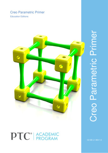
In a final presentation session all student projects werepresented and the observations in the design and productionprocess were discussed. Some student groups report that theywould have changed some design aspects after theirexperience in the workshop. As an example, the stability ofsome designs was inadequate as stability simulation was notconsidered in the design process. Many designs used plug-inconnectors to join luminaire screen panels. These had to bestrengthened by with glue in several cases, therebyincreasing the time to assemble the luminaire. One groupcreated a working model out of cardboard, which helpedsignificantly in improving the design and construction. Wewill will consider the need for working models in futureworkflows.Figure 17. Assembling, Luminaire “Onion” – Igor Milekic,Fabijan Farkas, Annabella Lintl, 20197RESULTSExamples in Figure 18 give an impression of the diversity ofluminaires that are produced with respect to the given designrequirements. Featured luminaires are table top and ceilinghung. All examples use an off-the-shelf 10 W LED lampmodule which is mounted on an aluminum sheet andprovides white light with a high color rendition index ( 95).8CONCLUSIONIn this paper, we demonstrated how production simulationcan be integrated into the design process. We consider theresults as a starting point for future research. We believe thata key issue in an improved design and production workflowlies in the simulation process of the production and thefeedback of the simulation results into the design process. Animportant factor is the generation of design variants that canbe evaluated automatically. Unfortunately, at the momentmany tools for simulating the production process areseparated from each other as well as from the parametricdesign process. We will target a much tighter integration ofsimulation tools into the design workflow in future research.This requires fast simulation results to provide almost realtime feedback or at least short interaction cycles. Thespecifications of production constraints and importantfeedback parameters (e.g. cost, time, maximum part sizes)need to be standardized on a technical and on a semanticlevel. File based data exchange should be replaced bystream-based data exchange for shorter feedback loops.Simulation should not be limited to production methods, butinclude the many dimensions of architectural design forimproving the overall design quality. We think that ourteaching environment is a very well-suited test environmentfor an improved design workflow that will integratesimulation tools into architectural design.ACKNOWLEDGMENTSWe would like to thank our colleagues Stefan Niedermairand Michal Rontsinsky for supporting our lectures withteaching visual scripting (Grasshopper). Additional thanksgo to Florian Rist and Walter Fritz for their efforts inteaching digital production methods and their support at theworkshops. Special thanks to our students for theircontributions.Figure 18. Luminaire examples: “Chill Bro Lamp” – AsmirMehic, Kaspar Ehrhart, Amila Imamovic. “Blade” – BlazGrudnik Tominc, Maximilian Schmid, Cheng Shi. “girih” –Denitsa Dimitrieva, Ada Gulyamdzhis, Behnaz Jalilifar.“MISShape” – Anes Delic, Ajla Kahric, Iuliia Radynska.571
REFERENCES1. Aish, R. & Hanna, S., 2017. Comparative evaluation ofparametric design systems for teaching design computation.Design Studies, Volume 52, pp. 144-172.2. Austern, G., Capeluto, I. G. & Grobman, Y. J., 2018.Rationalization methods in computer aided fabrication: Acritical review. Automation in Construction, Volume 90, pp.281-293.3. Celani, G. & Vaz, C. E. V., 2012. CAD Scripting andVisual Programming Languages for ImplementingComputational Design Concepts: A Comparison from aPedagogical Point of View. International Journal ofArchitectural Computing, Volume 10, pp. 121-137.4. Imbert, F. et al., 2013. Concurrent Geometric, Structuraland Environmental Design: Louvre Abu Dhabi. Vienna,Springer Vienna, pp. 77-90.5. Oxman, R., 2017. Thinking difference: Theories andmodels of parametric design thinking. Design Studies,6.Volume 52.6. Woodbury, R., 2010. Elements of Parametric Design.s.l.:Routledge.7. Wortmann, T. & Tunçer, B., 2017. Differentiatingparametric design: Digital workflows in contemporaryarchitecture and construction. Design Studies, Volume 52,pp. 173-197.8. Grasshopper, McNeel Associates,https://www.rhino3d.com/. As of 11 January 2020.9. Dynamo, https://dynamobim.org/. As of 11 January2020.10. Ultimaker Cura, 3D printing ura/. As of 9January 2020.11. VisiCut, A userfriendly tool to prepare, save and sendJobs to Lasercutters, http://visicut.org/. As of 9 January2020.12. CAMotics, Open-Source Simulation & Computer AidedMachining, http://camotics.org/. As of 9 January 2020.572Powered by TCPDF (www.tcpdf.org)
Grasshopper and Revit Dynamo. Visual scripting is usually based on the dataflow programming method. A program consists of a directed, acyclic graph where the nodes process data and edges represent data flow between nodes. Each node accepts input data, processes the data, and sends output to related nodes. The graph is automatically evaluated when