Transcription
Student and Academic EditionsCreo Parametric Primer02PTC Creo Parametric - PrimerC2-SE-L1-004-1.0
PTC Academic ProgramWritten byTim BrotherhoodandAdam HaasThese materials are 2012, Parametric Technology Corporation(PTC)Conditions of useCopying and use of these materials is authorized only in the schoolscolleges and universities of teachers who are authorized to teachCreo Parametric in the classroom.All rights reserved under copyright laws of the United States andother countries.All other use is prohibited unless written permission is obtained fromthe copyright holder.AcknowledgementsBased on the work of several UK trainers, in particular AlanPatterson.Proofing and comments – Curtis Siebenaller, Ayora Berry, MarkFischer, Adam Haas, Myron Moss, Phil Walker.Trialing materials -Feedbacktbrotherhood@ptc.comIn order to ensure these materials are of the highest quality, usersare asked to report errors to the author.Suggestions for improvements and other activities would also be verywelcome.Product codeC2-SE-L1-004-1.0Copyright 2011 Parametric Technology Corporation. All Rights Reserved. Copyright for PTC softwareproducts is with Parametric Technology Corporation, its subsidiary companies (collectively “PTC”), andtheir respective licensors. This software is provided under written license agreement, contains valuabletrade secrets and proprietary information, and is protected by the copyright laws of the United States andother countries. It may not be copied or distributed in any form or medium, disclosed to third parties, orused in any manner not provided for in the software licenses agreement except with written prior approvalfrom PTC.UNAUTHORIZED USE OF SOFTWARE OR ITS DOCUMENTATION CAN RESULT IN CIVIL DAMAGESAND CRIMINAL PROSECUTION.User and training guides and related documentation from PTC is subject to the copyright laws of theUnited States and other countries and is provided under a license agreement that restricts copying,disclosure, and use of such documentation. PTC hereby grants to the licensed software user the right tomake copies in printed form of this documentation if provided on software media, but only forinternal/personal use and in accordance with the license agreement under which the applicable softwareis licensed. Any copy made shall include the PTC copyright notice and any other proprietary noticeprovided by PTC. Training materials may not be copied without the express written consent of PTC. Thisdocumentation may not be disclosed, transferred, modified, or reduced to any form, including electronicmedia, or transmitted or made publicly available by any means without the prior written consent of PTCand no authorization is granted to make copies for such purposes. Information described herein isfurnished for general information only, is subject to change without notice, and should not be construedas a warranty or commitment by PTC. PTC assumes no responsibility or liability for any errors orinaccuracies that may appear in this document. 2012 PTCCreo Parametric 2.0 PrimerPage 2
PTC Academic ProgramContentsContents . 3Introduction . 5Understanding the Creo Parametric interface . 6What’s new in Creo Parametric . 9Working directories and saving your work . 10Working Directory Theory. 10Opening Files . 11Saving Files . 11Procedure – Part Modeling – Corner cube. 12Step 1: Set working directory and create a new part . 13Step 2: Start an Extrude . 15Step 3: Create a sketch to define the shape of the cube . 16Step 4: Complete the Extrude for the corner block . 20Step 5: Extrude the first hole . 25Step 6: Extrude the second hole . 29Step 7: Use the Hole tool to create the third hole . 34Step 8: Round edges of the cube . 38Step 9: Chamfer edges of the holes . 41Procedure – Part modeling - Strut . 44Step 1: Set working directory and create a new part. . 45Step 2: Start an Extrude . 47Step 3: Create a sketch to define the peg diameter . 48Step 4: Complete the Extrude that defines the length of the strut . 50Step 5: Extrude shoulder geometry . 51Step 6: Revolve a sketched arc to thin the center of the strut . 54Step 7: Round edges of the strut . 60Step 8: Chamfer the ends of the strut. 62Procedure – Assembly . 64Step 1: Set working directory and create a new assembly . 64Step 2: Adding the first component to the assembly . 66Step 3: Add the first strut to the assembly . 69Step 4: Applying colors and textures to the parts . 75Step 5: Assembling more struts . 77Procedure - Rendering. 81Step 1: Open the Render tab and apply a scene . 81 2012 PTCCreo Parametric 2.0 PrimerPage 3
PTC Academic ProgramStep 2: Draft render . 85Step 3: Adding perspective . 86Step 4: Render setup . 87Step 5: Final render . 88Procedure - Engineering drawing . 89Step 1: Set working directory and open cube corner . 90Step 2: New engineering drawing . 91Step 3: Changing the drawing scale . 93Step 4: Moving views . 95Step 5: Adding dimensions. 96Step 6: Adding annotations . 99Extension task . 101 2012 PTCCreo Parametric 2.0 PrimerPage 4
PTC Academic ProgramModule 1IntroductionThis primer will introduce you to the modeling,visualization and design tools in CreoParametric.Creo Parametric is a leading 3D design program,used by many of the top product developmentcompanies in the world.You will be taught how to use Creo Parametric tomodel two components for a construction kit - acube and a strut.You will then be shown how to put these togetherto form an assembly, create a photo-realisticrendered image and an engineering drawing. 2012 PTCCreo Parametric 2.0 PrimerPage 5
PTC Academic ProgramModule 2Understanding the Creo Parametric interfaceThe Main Creo Parametric interface looks like this.Main Interface TheoryThe Creo Parametric user interface is easy to navigate with the key tools for a particulartask contained in the ribbon across the top of the graphics area. Key elements of themain interface include:Quick Access Toolbar — Contains commonly used tools and functions.Ribbon Tabs — A set of tabs across the top of the interface. The active tab displays aset of tools in the ribbon immediately below. Here the View tab is active. 2012 PTCCreo Parametric 2.0 PrimerPage 6
PTC Academic ProgramGraphics Area — The working area ofCreo Parametric in which you view,create, and modify models such as parts,assemblies, and drawings.Message Area — The message area provides you with prompts, feedback, andmessages from Creo Parametric. Messages are logged and can be scrolled or themessage window dragged to display more lines.Dashboard — Locked at the top of the graphics area, the Dashboard appears whenyou create or edit a feature.– The Dashboard provides you with controls, inputs, status, and guidance forcarrying out a task, such as creating or editing a feature. Changes areimmediately visible in the graphics area.– Tabs along the bottom of the Dashboard provide additional feature options.– Dashboard icons on the left include feature controls while the Pause, Preview,Complete Feature or Component and Cancel Feature options are grouped rightof the center. 2012 PTCCreo Parametric 2.0 PrimerPage 7
PTC Academic ProgramDialog Boxes — Content-sensitive windows that appear,displaying and prompting you for information.Menu Manager — A cascading menu that appears on the farright during the use of certain functions and modes withinCreo Parametric. You select options working from top tobottom in this menu; however, clicking “Done” works frombottom to top. Bold menu options will be automaticallyselected if the middle mouse button is clicked. 2012 PTCCreo Parametric 2.0 PrimerPage 8
PTC Academic ProgramWhat’s new in Creo ParametricTo help existing CAD users, here is a list of the key changes in Creo Parametric 2.0 Tabbed ribbon menus with 90% of the tools instantly available. Customizable ribbon interface. The new Command Search tool lets you type a command and see a filtered listof tools. When you cursor over an item in the list, Creo locates and highlights thecommand in the ribbon. Learning Connector provides short on-demand “How to” videos linked to eachtool. New Shading with Edges display type. Starting a feature like extrude lets you select the sketch plane without seeing thesketch dialog box. Much simpler and now the quickest (CAD program) on thedraw! While sketching, holding down the ALT key lets you create references on-thefly without interrupting the sketch tool. Construction mode in sketcher. The new Center Rectangle tool lets you sketch a rectangle from its center. Enhanced geometry colors to help visualization and selection. Freestyle is a new subdivision modeler in Creo Parametric. Freestyle is similarto Warp but much more powerful and very easy to use. Take a look at thevacuum cleaner demo on YouTube. Dynamic Edit - Direct access to features and parameters with real timeregeneration. 3D Dragger handles make editing and positioning really easy. Automatic addition (protrusion) or removal (cut) of material when creatingExtrude or Revolve features. Extrude with taper or draft applied to the side surfaces of the extruded geometry. New, easy to use Corner Chamfer tool. Single sweep command combines variable section and simple sweep tools. Single helical sweep tool now offers variable section and variable pitch. Streamlined and enhanced measurement tools. Enhanced sheet metal tools including live flat pattern preview. Creo Parametric will open native Solidworks, Inventor and Solid Edge modelsmaking it easy to reuse legacy data when upgrading to Creo. Faster assembly, real time interference detection and easier 3D sections. 2012 PTCCreo Parametric 2.0 PrimerPage 9
PTC Academic ProgramWorking directories and saving your workThe Working Directory is the location for opening files from and saving new files to.Setting your Working Directory: Creo Parametric is started in a default working directory. The working directory is set before every session. When you exit Creo, it does notremember the working directory for the next session.Open Files - The File Open dialog box looks first in the working directory.Save Files - Files are saved to the folder they were opened from, this is not always theworking directory.Working Directory TheoryThe working directory is the designated location for opening and saving files. Thedefault working directory is the “Start in” location defined in the Creo Parametric starticon properties, typically “My Documents” or your “home” drive or folder on a network.If you are not using PTC’s Windchill PDMLink to manage your Creo Parametric data, itis best practice to organize your work by creating a folder for each project. Each timeyou start Creo Parametric, you should set the working directory to the folder you plan towork in. In this course you will be instructed to create a folder and set that as yourworking directory.There are four methods to set your working directory, use the method you are mostcomfortable with: From the Home tab - When Creo Parametric first opens, Click Select WorkingDirectoryfrom the Data group of the Home tab. Browse to locate the directoryyou wish to use, open it and click OK. This is the easiest and most straight forwardmethod. From the File menu – If the Home tab is not available - Click File ManageSession Select Working Directory. Browse to the location that is to be the newworking directory, select it and click OK. From the Creo Parametric Folder Tree or Browser - Right-click the folder that is tobe the new working directory and select Set Working Directory from the pop-upmenu. 2012 PTCCreo Parametric 2.0 PrimerPage 10
PTC Academic Program From the Creo Parametric File Open dialog box - Right-click the folder that is to bethe new working directory and select Set Working Directory from the pop-upmenu.You can browse directly to the working directory at any time by selecting WorkingDirectory in the folder view of the Navigator panel on the left of the Creo window.Opening FilesAfter you have set your working directory, you will see the files in that folder each timeyou click Open in Creo Parametric.You can use any of the following methods to open a file: Click File Open from the main menu, click Openfrom the Quick Accesstoolbar or click Openfrom the Home tab. Then, in the File Open dialog box,you either double-click the file you want to open or select the file and click Open. Browse to the desired folder using the Navigator to display its contents in thebrowser. Then, you either double-click the file you want to open or, right-click the filein the browser and select Open from the pop-up menu. Drag a file from the browser into the graphics area.The File Open dialog box is the equivalent of the Navigator and Browsercombination in the main interface.Saving FilesBy default, files are saved to the folder they were opened from. A new part, assembly,or drawing will be saved to the folder that is active when you click OK from the SaveObject dialog box.You can use any of the following methods to save a file: Click File Save from the File menu. Click Save Use the CTRL S keyboard shortcut.from the Quick Access toolbar.What have you learned? The layout of Creo Parametric’s user interface Interface items such as the Dashboard, dialog boxes, and the ribbon interface Working directories and file management 2012 PTCCreo Parametric 2.0 PrimerPage 11
PTC Academic ProgramProcedure – Part Modeling – Corner cubeScenarioThis section will teach you how to model acube shaped corner block for a constructionkit.You will create a new part, start an extrude,add a square sketch, and use this to extrudethe cube shape.Extruded circles will be used to create two ofthe holes and the Hole tool will be used for thethird hole.Rounds on the outer corners and chamfers onthe holes will complete the model. 2012 PTCCreo Parametric 2.0 PrimerPage 12
PTC Academic ProgramTask 1: Set working directory and create a new part1. Start Creo Parametric.2. In the Home tab, Data group, click Select Working Directory.3. In the Select Working Directory dialog box Navigate to the folder where you want to store your construction kit components.We suggest that you create a new folder (right-click and select New Folder fromthe pop-up menu) for each project you work on. After you have browsed into the working directory folder, click OK to set thatfolder as your working directory.The Corner Cube part you create will be saved to, and opened from, this“working directory”.4. Creating the new corner cube part model: From the Quick Access toolbar or Home tab,click New. In the New dialog box, notice the defaultobject Type is Part and Sub-type is Solid;these are the correct options for creating asolid part. Type CORNER CUBE in the Name field andclick OK.You cannot use spaces in filenames so useunderscores or hyphens instead. 2012 PTCCreo Parametric 2.0 PrimerPage 13
PTC Academic Program5. Changing the display of datum features: In the Graphics toolbar at the top of thegraphics area, disable the display of alldatum features except datum planes.The datum planes FRONT, RIGHT and TOP represent the 3D work space orframework for your model.Think of datum planes as the frameworkyour model will be built on.Datum planes have a front or positivesurface and back or negative surface.The frame showing the placement of eachdatum plane is colored brown when viewedfrom the front (positive side) and gray whenviewed from the rear (negative) side.What have you learned? Setting working directories and starting new parts. Controlling the display of datum features Datum plane theory 2012 PTCCreo Parametric 2.0 PrimerPage 14
PTC Academic ProgramStep 2: Start an ExtrudeThe easiest way to start creating solid geometry in Creo Parametric is to begin a3D feature, in this case an extrude, then select the sketch plane. Extrude is justone of the “sketch based” features in Creo Parametric.You will start an Extrude then select datum plane FRONT as your sketching plane.1. Starting an Extrude (sketched) feature and defining the sketch plane: Start the Extrudetool from the Shapes group of the Model tab.While using Creo Parametric, keep an eye on the prompt line at the bottom of thescreen. There you will see messages telling you what Creo is doing, if there is aproblem or what you need to do next. In this case you are being guided to selectthe sketch plane In the model tree or the graphics area, select datum plane FRONT.The Sketch tab will open and you will be able to start sketching. Two “Reference” lineswill be visible on the Front datum plane.A sketch needs a minimum of two Reference lines to locate the geometry youcreate. In this case, Creo Parametric has created these automatically based onthe other two datum planes.What have you learned? Starting an Extrude (sketched) feature. Selecting a sketch plane. The Ribbon interface workflow. 2012 PTCCreo Parametric 2.0 PrimerPage 15
PTC Academic ProgramStep 3: Create a sketch to define the shape of the cubeA 2D, 30 mm square will be sketched on datum plane FRONT. The square willbe drawn symetrical about the intersection of the reference lines using a CenterRectangle tool. You will add an equal length constraint on two adjacent sides ofthe square.1. Toggle off the display of datum planes: In the Graphics toolbar, disable thedisplay of all datum features.2. Sketching the rectangle: In the Sketch tab, select Centerfrom the RectangleRectangletypes drop-down menu. In the Graphics toolbar, click Sketch Viewto the screen.to reorient the sketch plane parallelThe model space will rotate until the sketch plane is parallel to the computer screen. Move the cursor over theintersection of the two referencelines at X1, when the cursor snapsto the intersection, click to set thecenter of the rectangle. Move the cursor diagonally and clickX2 to set a corner of the rectangle. Middle-click in the graphics area todeselect the rectangle tool. 2012 PTCCreo Parametric 2.0 PrimerPage 16
PTC Academic ProgramSketches are controlled by two types of parametric constraints.Dimension constraints allow you to alter sizes. Later you will use dimensionsto define the size of this rectangle.Geometric constraints including; equal length, parallelism, perpendicular,coincident, and so on. Creo has already applied many of these while you weresketching the square; to keep lines vertical/horizontal and make lines passthrough the origin. Next, to change this rectangle to a square, you will apply anequal length constraint.3. Adding an “Equal Length” sketcher constraint:You will add an Equal Length geometric constraint between two adjacent sides ofthe rectangle to make it a square. Creo Parametric is smart enough to removeone of the blue-gray (weak) dimensions to avoid over constraining the sketch. Click X1 to select the tophorizontal line in the rectangle.The line should change color togreen to show it is selected. Press and hold CTRL on thekeyboard, then click X2 to addthe vertical line to the selection.This line will also change colorto green. With both lines selected, rightclick and select Equal from thepop-up menu (shown as X3).Notice that one of the blue-gray “weak” dimensions has disappeared and a pair of L1(Equal Length) constraints have appeared next to the selected lines. 2012 PTCCreo Parametric 2.0 PrimerPage 17
PTC Academic ProgramThere should now be just one dimension on the sketch. This is called a “weak”dimension and it is displayed in a blue-gray color. Sketch dimensions are“parametric” meaning when you change them the geometry will change to matchthe new value. You will change the dimension to 30 and lock it.4. Changing a dimension to 30: Move the cursor over the dimensionvalue shown here at X1, and doubleclick. Type the new value of 30 and thenpress ENTER. Click in a blank area of the graphicswindow to de-select the dimension.The size of the square will change accordingto the new dimension value. You have justseen parametric control in action. If necessary, click Refit from theGraphics toolbar. This will refit thesketch in the graphics area.The position and size of sketch lines arecontrolled by a combination of dimensionconstraints and geometric constraints.Notice that the dimension changed to a bluecolor, showing that it is now a strongdimension.Sketch geometry controlled by weak or strong dimensions can still be dragged. To fixdimensions so they cannot change accidentally, they must be locked.5. Locking a dimension Click to select the dimension. It turnsgreen to show it is selected. Right-click and hold on the selecteddimensions and from the pop-upmenu, select Lock. Click in blank area of the graphicswindow to de-select the dimension 2012 PTCCreo Parametric 2.0 PrimerPage 18
PTC Academic ProgramThe dimension will now be colored brown toshow it is locked.6. Reorient the model to its defaultorientation: Press CTRL D (on the keyboard,hold down the CTRL key and pressD).You will now see a preview of the extrudedsquare sketch.7. Click OKfrom the Close group of the Sketch tab to complete the sketch andreturn to the Extrude dashboard.What have you learned? Creating sketch geometry - center rectangles. Geometric constraints – overview, apply equal length. Dimension constraints, changing, weak, strong and locked. Viewing the model – default, flat sketch view and refit. Datum display - visibility. Dashboard interface. 2012 PTCCreo Parametric 2.0 PrimerPage 19
PTC Academic ProgramStep 4: Complete the Extrude for the corner blockYou will now edit the depth of the Extrude to be 30, extruding equally in bothdirections from the sketch plane so that the datum planes are at the center of thecube; this will be helpful when locating the holes later in this exercise. Extrude isa sketch based feature and this example used an “Internal” sketch.1. If necessary, use the Graphicstoolbar to disable the display ofall datum features.You can change how the extrude is defined either in the dashboard or on themodel. Every element that defines the Extrude feature can be accessed fromthe dashboard.After a feature is complete, you can use Edit Definition to re-open the dashboardand edit the feature. 2012 PTCCreo Parametric 2.0 PrimerPage 20
PTC Academic Program2. Making changes to the extrude using the dashboard: In the extrude dashboard, click on the smalltriangle next to the depth option X1 to openthe drop-down menu. Select Symmetricfrom the list. Click in the depth field X2, type 30 and pressENTER. Click Complete Featurefrom thedashboard.In the Graphics toolbar, clickto refit themodel in the graphics screen. The new extrude feature is added to the Model Treeon the left of the screen.3. Saving your work In the Quick Access toolbar, click Save . In the Save Object dialog, click OK to specifythat the model will be saved to your workingdirectory.If the extrude dashboard mysteriously closes before intended, you probablymiddle mouse clicked. Engineers use many shortcuts to speed up their work andmiddle click is the shortcut to select Complete Featuredashboard! and close theIf you need to re-open the dashboard, right-click on Extrude 1 in the model treeand select Edit Definition from the pop-up menu. 2012 PTCCreo Parametric 2.0 PrimerPage 21
PTC Academic ProgramWhat have you learned? Datum display - visibility. Viewing the model – Default orientation. Extrude – Remove material (cut), symmetric and through all. Dashboard to define and edit feature options. Edit features in the graphics area. Model Tree – stores features. Edit Definition to re-open and change existing features. 2012 PTCCreo Parametric 2.0 PrimerPage 22
PTC Academic ProgramDynamic ViewingThe orientation of your model within the graphics area is easily controlled using themouse and the Graphics toolbar.3D mode2D and 3D modeHold down the key and roll the mouse. Spin Zoom Pan Zoom Fine Zoom Course Zoom or 2D mode Turn Pan Zoom It is possible to ‘lose’ the model from the graphics area by spinning or panningthe model completely out of the display. If your model ever disappears from thewindow, click Refitfrom the Graphics toolbar or press CTRL D. 2012 PTCCreo Parametric 2.0 PrimerPage 23
PTC Academic ProgramGraphics ToolbarThe Graphics toolbar at the top of the graphics area controls how the model appears inthe graphics area.Experiment with the options to see the effect they have on the appearance of themodel. 2012 PTCCreo Parametric 2.0 PrimerPage 24
PTC Academic ProgramStep 5: Extrude the first holeInstead of adding material, the extrude tool can also be used to remove material,in this case we use an extruded cut that is shaped like a circle.This extrude feature will be created by sketching an 8 mm diameter circle on thefront face of the cube. The extrude will remove material and intersect the entirecube.1. If necessary, use the Graphics toolbarto disable the display of all datumfeatures.2. Starting an Extrude (sketch based) feature and defining the sketch plane: Start the Extrudetool from the Shapes group of the Model tab.3. Starting an internal sketch: Press CTRL D to reorient the model. In the graphics area, click to select the frontface of the cube X1, as the sketch plane.The Sketch tab will open and you will beable to start sketching immediately. To make sketching easier while you arelearning, click Sketch Viewfrom theGraphics toolbar; this will reorient the sketchplane parallel to the computer screen. 2012 PTCCreo Parametric 2.0 PrimerPage 25
PTC Academic Program4. Sketching a circle: Click Center and Point circlefrom theSketching group of the Sketch tab. Move the cursor until it snaps to theintersection of the reference lines X1, andclick to locate the center of the circle. Move the cursor away from the center andclick at X2 to complete the circle. Middle-click in the graphics area to deselectthe circle tool. Double-click the diameter dimension valueX1, then type 8 and press ENTER. Click in a blank area of the graphics windowto deselect the dimension.The circle will resize and the dimension willchange color to show it is now strong.5. Reorient the model to its default orientation: Press CTRL D to reorient the model. Click OKfrom the Close group of the Sketch tab to complete the sketch andreturn to the Extrude dashboard. 2012 PTCCreo Parametric 2.0 PrimerPage 26
PTC Academic ProgramBy default, Creo Parametric will display a preview ofthe extruded circle, adding material, away from themodel. Drag the drag handle (small white square)away from the
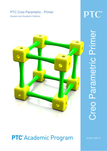
Creo Parametric Primer. PTC Creo Parametric - Primer . Student and Academic Editions . 02 C2-SE-L1-004-1.
