Transcription
GRUNDFOS CIM/CIUCommunication InterfacesDISTRICT HEATINGCIM/CIUCOMMUNICATIONINTERFACESCOMPLETE CONTROL FOR PUMPS AND PUMP SYSTEMS
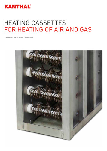
MANAGE YOUR SYSTEMS WITHCIM/CIU COMMUNICATIONINTERFACESFor complete control of pump systems, the Grundfos fieldbusconcept is the right solution. The innovative CommunicationInterface Module (CIM) and the Communication Interface Unit(CIU) enable data communication via open and interoperablenetworks such as Modbus RTU Modbus TCP BACnet MS/TP BACnet IP LONWorks PROFIBUS DP PROFINET IO EtherNet/IP 3G/4G cellular data connection and SMS Grundfos Remote Management (GRM) Grundfos iSOLUTION Cloud (GiC)WHY CIM/CIU CONNECTIVITY INTERFACES?The series of Grundfos CIM/CIU communication interfaces offerease of installation and commissioning, user-friendliness and greatvalue for money in the long term. All modules are based onstandard functional profiles for an easy integration into thenetwork and easy understanding of data points. Flexible wide range power supply 24-240 VAC/VDC (CIU unit) Pumps and controllers have better reliability with reduceddowntime, due to monitoring and control functionality on a PLC,BMS/ SCADA system The operational cost of pumps can be lowered by reducingsetpoints to match precise system needs via remote control Remote monitoring and control via PLC, BMS/ SCADA systemsreduce manual settings, monitoring time and travel time to sitesor installations Enable predictive maintenance and fast reaction time on processchanges and exceptions One solution for all products with a modular design prepared forfuture needs One solution offering complete process monitoring and control Easy to install and commission, as Grundfos delivers the requiredsupport files and functional profile manualsNetworkCIM modulemounted inCIU unitGENIbusCIM modulemountedin productCIM modulemountedin productDDA withE-Box containingCIM moduleAvailable communication interfaces CIM 050 for GENIbus CIM 060 for radio communication to Grundfos GO Remote CIM 100/110 for LONWorks CIM 150 and E-Box 150 for PROFIBUS DP CIM 200 and E-Box 200 for Modbus RTU CIM 260 for 3G/4G cellular networks CIM 280 for Grundfos iSOLUTIONS Cloud/GRM CIM 300 for BACnet MS/TP2 CIM 500 for PROFINET IO, Modbus TCP, BACnet IP, EtherNet/IPand Grundfos iSOLUTIONS Cloud E-Box 500 for PROFINET IO, Modbus TCP, EtherNet/IP,Grundfos iSOLUTIONS Cloud CIU 900 unit for any CIM interface CIU 901 CIU unit with IO board CIU 902 unit for wastewater AUTOADAPT CIU 903 for SQFlex/MGFlex GiM CIU unit for Grundfos iSOLUTION MONITOR (GiM)
CIM & CIU COMMUNICATION INTERFACES FIELDBUS COMMUNICATIONGrundfos Communication Interface Modules (CIM) and Units (CIU)Creating intelligent communications solutions for applications in Industry, Building Services and Water Utility.Mounting CIM in CIU unit or E-BoxCIMCIU 900CIM 100/110CIU 100/110assemblyPROFIBUS DPCIM 150CIU 150assemblyModbus RTUCIM 200CIU 200assemblyBACnet MS/TPCIM 300CIU 300assemblyCellular 3G/4G forSCADACIM 260 EU/USCellular 3G/4G forGrundfos iSOLUTIONSCloud/GRMLONWorksIndustrial EthernetCIU 901(IO 270)CIU 902(AUTOADAPT)CIU 903(SQ Flex/MGFlex)GiM CIUE-Box(Small DDA)CIU 152assemblyE-Box 150CIU 201assemblyCIU 202assemblyE-Box 200CIU 260 EU/USassemblyCIU 261 EU/USassemblyCIU 262 EU/USassemblyCIM 280 EU/USCIU 280 EU/USassemblyCIU 281 EU/USassemblyCIU 282 EU/USassemblyCIU 283 EU/USassemblyCIU 284 EU/USassembly (CIM 280GDP only)CIM 500CIU 500assemblyCIU 501assemblyCIU 502assemblyCIU 503 assemblyGrundfos iSOLUTIONS Cloud/GRMonlyCIU 504 assemblyGrundfosiSOLUTIONSCloud onlyE-Box 500Note: All devices denoted as “assembly” consist of two parts, that are ordered separately.CIM modulesThe CIM is an add-on communication module installed internally.Single pumps:· E-pumps based on MGE motor model H/I/J· E-pumps based on MGE motor 11-22 kW· MAGNA3 circulator pumpsBoosters:· Hydro/Control MPC, CU 352· DDD control, CU 354· Hydro Multi-E and Hydro Multi-B· MAGNA3-D twin circulator pumps· TPED twin pump model H/I/JWater Utility controllers:· Dedicated Controls, CU 362· Level Control, LC 2X1 wastewater, LC 2X2 submersibleCIU 900 wall-mounted/DIN rail unitThe CIU 900 with internal power supply is for Grundfos products that donot support the internal mounting of the CIM module.· TPED 11-22 kW· CUE drive for various standard pumps· MP 204 motor protector· DDA model XLCIU 901 wall-mounted/DIN-rail unitA CIU 900 unit with additional I/O board integrated which contains:· 2 configurable inputs (digital or analog 0/4-20 mA, 0-10 V)· 1 Relay output (230 V, 2 A)· 1 Analog signal output (0-10 V)· 1 Temperature input (Pt100/Pt1000, 2-wire)· 2 digital inputsSupported from CIM 200 Modbus RTU, CIM 260 3G/4G cellular, CIM 280Grundfos iSOLUTIONS Cloud/GRM, CIM 500 (Modbus TCP, GrundfosiSOLUTIONS Cloud/GRM)CIU 902 wall-mounted/DIN rail unitA CIU 900 unit but with integrated powerline communication to connect1 to 4 wastewater AUTOADAPT pumps.Supported from:· CIM 150 PROFIBUS DP· CIM 200 Modbus RTU· CIM 260 cellular· CIM 280 Grundfos ISOLUTIONS Cloud/GRM· CIM 500 for Modbus TCP, PROFINET, GiC/GRMCIU 903 wall-mounted/DIN rail unitA CIU 900 unit but with integrated powerline communication to connectwastewater MGEFlex and SQFlex pumps.Supported from:· CIM 280 Grundfos ISOLUTIONS Cloud/GRM· CIM 500 for GiC/GRM (not for solar power).GiM CIUA CIU 900 unit with additional I/O board integrated for GiMSupported from:· CIM 280 Grundfos iSOLUTIONS Cloud/GRM· CIM 500 for GiC/GRME-BoxAn external communication unit for small DDA dosing pumps.· E-Box 150 PROFIBUS DP with built-in CIM 150· E-Box 200 Modbus RTU with built-in CIM 200· E-Box 500 Ethernet with built-in CIM 500 for support of PROFINET IO,Modbus TCP, EtherNet/IP and Grundfos iSOLUTIONS Cloud/GRM3
FIELDBUS COMMUNICATIONCIM/CIU interface products mapped to protocolsMAGNA3-DTwin pump2)MAGNA 3TPED 11-22 Twin pumpE-pumpkW Twin TPED Model MGE modelpumpH/I/J 1)H/I/J 11-22 kWCUE TPE22-55 kWHydro MPC(CU 352)Multi-EMGE11-22 kWmodel G/FMulti-EModelH/I/J 1)MP 204built-inbuilt-inbuilt-inDedicatedControls(CU 362)WastewaterAUTOADAPT1-4 pumpsLevelControllerLC 2x1,LC 2x2CIM 050CIU 902 CIM 050CIM 050DDAdosing USDPPROFINET IOModbus TCPModbus RTUEtherNet/IPBACnetMS/TPBACnet IPGrundfosiSOLUTIONSCloud /GRM4)Cellular dataconnectionfor SCADAand SMS4)Radio toGrundfosGO Remotebuilt-inbuilt-inbuilt-inCIM 050CIM 050CIM 050CIM 110CIM 1002x CIU 900 2x CIM 100CIM 110CIM 100CIU 900 CIM 100CIM 110CIU 900 CIM 100CIM 110CIM 150CIM 1502x CIU 900 2x CIM 150CIM 150CIM 150CIU 900 CIM 150CIM 150CIU 900 CIM 150CIM 150CIU 900 CIM 150CIM 150CIU 902 CIM 150CIM 150CIU 900 CIM 150 orE-Box 150CIM 500CIM 5002x CIU 900 2x CIM 500CIM 500CIM 500CIU 900 CIM 500CIM 500CIU 900 CIM 500CIM 500CIU 900 CIM 500CIM 500CIU 902 CIM 500CIM 500CIU 900 CIM 500 orE-Box 500CIM 500CIM 5002x CIU 900 2x CIM 500CIM 500CIM 500CIU 900 CIM 500CIM 500CIU 900 CIM 500CIM 500CIU 900 CIM 500CIM 500CIU 902 CIM 500CIM 500CIU 900 CIM 500 orE-Box 500CIM 200CIM 2002x CIU 900 2x CIM 200CIM 200CIM 200CIU 900 CIM 200CIM 200CIU 900 CIM 200CIM 200CIU 900 CIM 200CIM 200CIU 902 CIM 200CIM 200CIU 900 CIM 200 orE-Box 200CIM 500CIM 5002x CIU 900 2xCIM 500CIM 500CIM 500CIU 900 CIM 500CIM 500CIU 900 CIM 500CIM 500CIM 300CIM 3002x CIU 900 2x CIM 300CIM 300CIM 300CIU 900 CIM 300CIM 300CIU 900 CIM 300CIM 300CIM 300CIM 500CIM 5002x CIU 900 2x CIM 500CIM 500CIM 500CIU 900 CIM 500CIM 500CIU 900 CIM 500CIM 500CIM 500CIM 280/CIM 500CIM 280/CIM 5002x CIU 900 2x CIM 280/ 2xCIM 500CIM 280/CIM 500CIM 280/CIM 500CIU 900 CIM 280/CIM 500CIM 280/CIM 500CIU 900 CIM 280/CIM 500CIM 280/CIM 500CIU 900 CIM 280/CIM 500CIM 280/CIM 500CIU 902 CIM280/CIM 500CIM 280/CIM 500CIM 260CIM 2602x CIU 900 2xCIM 260CIM 260CIM 260CIU 900 CIM 260CIM 260CIU 900 CIM 260CIM 260CIU 900 CIM 260CIM 260CIU 902 CIM 260CIM 260built-inbuilt-inbuilt-inbuilt-inCIM 060CIU 902 CIM 060CIU 900 CIM 500 orE-Box 500CIU 900 CIM 500 or CIM 280/E-Box 500 CIM 500*built-inNote: To create a CIU xxx solution, you need to order a CIU 900 the required CIM xxx interface and mount the CIM xxx interface into CIU 900.This is the same for a CIU xx1, CIU xx2, CIU xx3.*EU/US version only1) A second CIM module can optionally be mounted in pump no. 2 for redundancy2) MAGNA3-D model D requires 1x CIM in master head, MAGNA3-D models A-C require a CIM in each head (for LONWorks 2x CIM 100) 3) Small DDA uses the E-Box, whereas DDA XLuses the CIU unit plus the appropriate CIM module4) CIM 260 3G/4G cellular and CIM 280 Grundfos iSOLUTIONS Cloud/GRM 3G/4G cellular are available in regional versions for EU and for USA (consider needed 3G/4G frequencybands) GiM 1.0 require variant CIM 280 GDP version, CIM 500 require version with GDP protocol. GiC require a CIM 280 GiC EU/US variant.Note: Hydro Multi-B is supported by CIM 050 GENIbus, CIM 110 LON, CIM 200 Modbus RTU, CIM 300 BACnet MS/TP, CIM 500 (Modbus TCP, BACnet IP), CIM 260 3G/4G cellular,CIM 280 Grundfos iSOLUTIONS Cloud/GRM 3G/4G cellular.Note: E-pumps are CRE/CRNE/CRIE, MTRE, CME, TPE2/TPE3, NBE/NKE.4built-in
PROTOCOLS MAINLY USED IN BUILDING SERVICES FIELDBUS COMMUNICATIONBACnet IP, BACnet MS/TP, LONWorks- For pumps and boostersGeneral CIU 900 dataData pointsTransmission speedsPortsIP settingsBACnet IP(set rotary switch to position 2)10/100 Mbit/s2x RJ45built-in webserverCIM 300 BACnet MS/TP CommunicationProtocolTransceiverTransmission speedsBACnet master addressE-pumps 11 kWE-pumps model JCUEE-pumps 11-22 kWMulti-E, TPEDHydro MPC/Control MPCHydro Multi-BGENIbusRS-485Screened, double twisted-pair1200 m/4000 ftCIM 500 BACnet IP CommunicationProtocols if sensor installeds* available with sensor or TPE2000 and TPE31 differential or absolute, dependson sensor2Not standard for Control MPCOperating Mode Setpoint Control Mode H HG only for MGE model G or laterH only for MGE model H or laterControlGENIbus CommunicationProtocolTransceiverRecommended cable typeMaximum cable lengthBACnet IP, BACnet MS/TP, LONWorksMAGNA324-240 VAC/VDC, -10 %/ 15 %0-60 HzMax. 11 WIEC: 0.2-4 mm2, UL: 24-12 AWGIP 54, according to IEC 605296 x M16 Ø4 - Ø10-20 C to 45 C (-4 F to 113 F)-20 C to 60 C (-4 F to 140 F)182 x 108 x 82 mmMAGNA/UPESupply voltageFrequencyPower consumptionCable sizeEnclosure classCable entryOperating temperaturesStorage temperaturesDimensions (H/W/D)BACnet MS/TP (Master)RS-4859.6, 19.2, 38.4, 76.8 kbits/s0-127Relay ControlTank filling status StatusOperating Mode status Control Mode Status Feedback Alarm/warning information G Bearing Service InformationTank filling control Measured DataPower/Energy Consumption Pressure (Head) s*s* 2sFlow s*s*H s 2Relative Performance Speed and Frequency Digital Input/Output s1Motor CurrentMotor VoltageCIM 100 LON for pump/CIM 110 LON for booster & twin pumpcommunicationProtocolTransceiverTransmission speedRemote FlowsInlet Pressure 1sRemote Pressure 1LONtalkFTT-1078 kbits/sLevelRemote TemperatureExample with BACnet IPsH sG ssH ssG ssH ssH sssssssssH s G ssH sBearing TemperaturesH ssAuxilary Sensor InputssH sOperation Time (Run Time) Total on time Number Of StartsTo controller/SCADA G sG sMotor TemperaturePump Liquid TemperatureG only Volume H sCUE sAmbient TemperatureH sH sInlet and Outlet TemperaturesHeat energy meter s ss HOutlet Pressure 1H sH sssFeed Tank L evelH sH sssAlarm/Status information Operation Time (Run Time) SpeedH Line current/power consumptionH Motor temperatureH Number of startsH Subpump DataE-pump11-22 kW withCIM 500 built-inMAGNA3with CIM 500built-inHydro MPCwith CIM 500built-inControl pump: force to stop/autoNote: E-pumps CRE/CRNE/CRIE, MTRE, CME, TPE2/TPE3, NBE/NKE.Note: TPED twin pump model F or G in range 3-22 kW needs always 2 CIU modules.Note: MAGNA3-D twinpump model D requires 1x CIM interface installed in master head.For LONWorks 1x CIM 110 installed in master head.5
PROTOCOLS MAINLY USED IN BUILDING SERVICES FIELDBUS COMMUNICATIONBACnet IP, BACnet MS/TP- For water utility productsGeneral CIU 900Data pointsBACnet IP, BACnet MS/TPLC 2x224-240 VAC/VDC, -10 %/ 15 %0-60 HzMax. 11 WIEC: 0.2-4 mm2, UL: 24-12 AWGIP 54, according to IEC 605296 x M16 Ø4 - Ø10-20 C to 45 C (-4 F to 113 F)-20 C to 60 C (-4 F to 140 F)182 x 108 x 82 mmLC 2x1Supply voltageFrequencyPower consumptionCable sizeEnclosure classCable entryOperating temperaturesStorage temperaturesDimensions (H/W/D) System operation mode Active alarms/warnings Status/function of float switches Presence of sensors System control source (Manual/Auto) System and pumps control levels Water level 3 x user defined sensor inputs Float switches Digital inputs Running/Stopped Active alarms/warnings System ControlReset alarmInterlock pitCustom relay control (On/Off/Pulse)GENIbus CommunicationProtocolTransceiverRecommended cable typeMaximum cable lengthPump ControlGENIbusRS-485Screened, double twisted-pair1200 m/4000 ftCIM 500 BACnet IP CommunicationProtocolTransmission speedsPortsIP settingsPumps On/Off/AutoPump downConfigurationSet system and pumps control levelsSystem statusSystem mode (single/multi)BACnet IP(set rotary switch to position 2)10/100 Mbits/s2x RJ45built-in webserverReal time clock (read and set)Water level maxIn/out flowCIM 300 BACnet MS/TP CommunicationProtocolTransceiverTransmission speedsBACnet master addressPower/Energy consumptionBACnet MS/TP (Master)RS-4859.6, 19.2, 38.4, 76.8 kbits/s0-127Specific energyVolumeOverflow volume/time/counterOperation timeOperation time for simultaneous pumpsMixer average starts per hoursExample with CIM 500To controller/SCADASwitch8 x I/O logic outputsDigital OutputsPump statusPresence of pumpPump enabled/disabledAuxiliary equipment statusControl source Operation time 1 1Starts counter (total/average) 1 1 2 2 3 3Latest continuous operation timeMax continuous operation timeLC 2x1LC 2x2Time to servicePulse Flow meterCurrent (actual/latest) Voltage/frequencyCurrent asymmetryPower/Power factor/Energy consumptionMotor temperatureInsulationWater in oil1) Available as 3 datapoints for yesterday, today and totalFor information related to Grundfos iSOLUTIONS Cloud please contact Grundfos2) LC 2X1 and LC 2X2 only have actual current3) LC 2X1 and LC 2X2 do not measure power factor6
FIELDBUS COMMUNICATION PROTOCOLS MAINLY USED AT INDUSTRIAL AUTOMATION AND WATER UTILITYPROFINET IO, Modbus TCP, EtherNet/IP, PROFIBUS DP, Modbus RTU- For pumps and boostersGeneral CIU 900, CIU 901, CIU 902, CIU 903Data pointsProtocolTransceiverRecommended cable typeMaximum cable lengthGENIbusRS-485Screened, double twisted-pair1200 m/4000 ftCIM 500 PROFINET IO, Modbus TCP, EtherNet/IPCommunicationProtocolTransmission speedsPortsConformance classPROFINET IO (rotary switch position 0)Modbus TCP (rotary switch position 1)EtherNet/IP (rotary switch position 3)10/100 Mbits/s2x RJ45BCIM 200 Modbus RTU CommunicationProtocolTransceiverTransmission speedsParity settingsStop bitsModbus Slave addressModbus RTURS-4851.2, 2.4, 4.8, 9.6, 19.2, 38.4 kbits/sEven, Odd or No parity1 or 21-247, set via rotary switchesCIM 150 PROFIBUS DP CommunicationProtocolTransceiverImplementation classTransmission speedsSlave addressPROFIBUS DPRS-485DP-V09600 bits/s to 12 Mbit/s1-126, set via rotary switchesExample with CIM 500To controller/SCADASwitchCIU 500GENIbusMP 204E-pump11-22 kWwith CIM 500built-inMAGNA3with CIM 500built-inHydro/Control MPCwith CIM 500built-inNot standard for Control MPC3Not supported for all pump variantsH only MGE model H or later G only MGE model G or laterControlOperating ModeSetpointControl ModeRelay ControlTank filling controlStatusOperating Mode StatusControl Mode StatusFeedbackAlarm and warning informationBearing Service informationTank filling status informationMeasured DataPower/Energy ConsumptionPressure (Head) 1FlowRelative PerformanceSpeed and FrequencyDigital Input/OutputMotor CurrentDC Link VoltageMotor VoltageRemote FlowInlet Pressure 1Remote Pressure 1LevelMotor TemperatureRemote TemperaturePump Liquid TemperatureBearing TemperaturesAuxilary Sensor InputOperation Time (Run Time)Total on timeTorque (N/A on 1-phased motors)Number Of Starts H MP 2042Hydro Multi-B ifferential or absolute, dependsdon sensorHydro MPC/Control MPC1Multi-E, TPEDs* available with sensor or TPE 2000and TPE3CUEE-pumps 11-22 kWGENIbus Communications if sensor installedE-pumps 11 kWE-pumps model JCIU 902 is used together with wastewater AUTOADAPT pumpsCIU 903 is used together with MGEFlex and SQFlex pumps, andonly with CIM 280 for Grundfos iSOLUTIONS CloudPROFINET IO, Modbus TCP, EtherNet/IP, PROFIBUS DP, ModbusRTUMAGNA324-240 VAC/VDC, -10 %/ 15 %0-60 HzMax. 11 WIEC: 0.2-4 mm2, UL: 24-12 AWGIP 54, according to IEC 605296 x M16 Ø4 - Ø10-20 C to 45 C (-4 F to 113 F)-20 C to 60 C (-4 F to 140 F)182 x 108 x 82 mmMAGNA/UPESupply voltageFrequencyPower consumptionCable sizeEnclosure classCable entryOperating temperaturesStorage temperaturesDimensions (H/W/D) H s*s* G onlyG sG sG ssG ssG sH ss s*s* sssssssss VolumeH sCUE sAmbient TemperatureInlet and Outlet TemperaturesHeat energy meter Outlet Pressure 1Feed Tank LevelPhase VoltagesLine Voltages/Currents/FrequencyStart/Run CapacitorVoltages Angles Cos phiInsulation resistanceStarts/h and auto restarts/24hSubpump Data (for each sub pump in the system)Status informationAlarm informationOperation Time (Run Time)SpeedLine current/power consumptionMotor temperatureNumber of startsControl pump: forc to stop/autoH sH sssHH sH sH sH s 2sss s H s 2 2 s H sH sH sH ssssH ssH s sss ss HHHH Note: E-pumps CRE/CRNE/CME, MTRE, CHIE, TPE2/TPE3, NBE/NKENote: For DDA dosing pumps please view to DDA related pagesNote: TPED twin pump model F or G in range 3-22 kW needs always 2 CIU modulesNote: MAGNA3-D twin pump model D only requires 1x CIM interface installed in master headNote: Hydro Multi-B only supported by Modbus RTU and Modbus TCP7
USED FOR COMMUNICATION IN WATER UTILITY FIELDBUS COMMUNICATIONPROFINET IO, Modbus TCP, EtherNet/IP, PROFIBUS DP, Modbus RTU- For water utility productsGeneral CIU 900, CIU 901, CIU 902CIU 902 is used together with wastewater AUTOADAPT pumpsReset alarmGENIbusRS-485Screened, double twisted-pair1200 m/4000 ftCIM 500 PROFINET IO, Modbus TCP, EtherNet/IPCommunicationTransmission speedsPortsConformance class Interlock pit Custom relay control (On/Off/Pulse) Pump ControlPumps On/Off/AutoProtocol System Control Pump downGENIbus CommunicationProtocolTransceiverRecommended cable typeMaximum cable lengthWastewaterAUTOADAPTCIU xx2*PROFINET IO, Modbus TCP, EtherNet/IP, PROFIBUS DP,Modbus RTUDedicatedControlsCU 36224-240 VAC/VDC, -10 %/ 15 %0-60 HzMax. 11 WIEC: 0.2-4 mm2, UL: 24-12 AWGIP 54, according to IEC 605296 x M16 Ø4 - Ø10-20 C to 45 C (-4 F to 113 F)-20 C to 60 C (-4 F to 140 F)182 x 108 x 82 mmLC 2x1/ LC 2x2Supply voltageFrequencyPower consumptionCable sizeEnclosure classCable entryOperating temperaturesStorage temperaturesDimensions (H/W/D)Data pointsPROFINET IO (rotary switch position 0)Modbus TCP (rotary switch position 1)EtherNet/IP (rotary switch position 3)10/100 Mbits/s2x RJ45B ConfigurationSet system and pumps control levels System statusSystem operation mode Active alarms/warnings Status/function of float switches Presence of sensors Real time clock (read and set) Pit mode (single/multi) System control source (Manual/Auto) System and pumps control levels Water level In/ out flow or pulse flow meter 5 Power/Energy consumption 1Water level max Specific energy Volume 1CIM 200 Modbus RTU CommunicationOverflow volume/time/counterProtocolTransceiverTransmission speedsParity settingsStop bitsModbus Slave addressOperation timeModbus RTURS-4851.2, 2.4, 4.8, 9.6, 19.2, 38.4 kbits/sEven, Odd or No parity1 or 21-247, set via rotary switches 1 1 Operation time for simultaneous pumps 1 Mixer average starts per hours 3 x user defined sensor inputs Float switches Digital inputs 8 x I/O logic outputsDigital Outputs Pump statusPresence of pumpCIM 150 PROFIBUS DP CommunicationProtocolPROFIBUS DPTransceiverRS-485Implementation classDP-V0Transmission speeds9600 bits/s to 12 Mbit/sSlave address 1-126, set via rotary switches Pump enabled/disabledTo controller/SCADASwitchRunning/Stopped Control source Operation time 1 1 1Starts counter (total/average) 1 1 1 Auxiliary equipment status Max continuous operation timeTime to service Flow (actual/latest)Current (actual/latest)Voltage/frequencyPower/Power factor/Energy consumption 2Current asymmetry 3 3Motor temperature Insulation Water in oil Special (Modbus only)Hour log (latest 72h of main pit/pump values)DedicatedControls(CU 362)8WastewaterAUTOADAPT1-4 pumpsLC 2xx Active alarms/warningsLatest continuous operation timeExample with CIM 500 Event log (50 latest alarms/warnings w. time stamp) 4 User defined data log (40000 registers) 4 1) Available as 3 datapoints for yesterday, today and totalFor information related to Grundfos iSOLUTIONS Cloud please contact Grundfos2) LC 2X1 and LC 2X2 only have actual current3) LC 2X1, LC 2X2 and AUTOADAPT do not measure power factor4) LC 2X1 and LC 2X2 only have 40 logs5) LC 2X2 only*To create a CIU 152, you order CIU 902 CIM 150. To create a CIU 202, you order CIU 902 CIM 200.To create a CIU 502, you order CIU 902 CIM 500
FIELDBUS COMMUNICATION USED FOR CLOUD/CELLULAR COMMUNICATIONCellular data connection to SCADA or operation via SMS- For pumps and boostersGENIbus communicationProtocolTransceiverRecommended cable typeMaximum cable lengthGENIbusRS-485Screened, double twisted-pair1200 m/4000 ftCIM 260 3G/4G cellularMulti-E, TPEDHydro MPC/Control MPCHydro Multi-BMP 204s if sensor installedCUEE-pumps 11-22 kWCIU 902 is used together with wastewater AUTOADAPT pumpsCIU 903 is used together with MGEFlex and SQFlex pumps, andonly with CIM 280 for Grundfos iSOLUTIONS CloudData pointsE-pumps 11 kWE-pumps model J24-240 VAC/VDC, -10 %/ 15 %0-60 HzMax. 11 WIEC: 0.2-4 mm2, UL: 24-12 AWGIP 54, according to IEC 605296 x M16 Ø4 - Ø10-20 C to 45 C (-4 F to 113 F)-20 C to 45 C (-4 F to 113 F)182 x 108 x 82 mmMAGNA3Supply voltageFrequencyPower consumptionCable sizeEnclosure classCable entryOperating temperaturesStorage temperaturesDimensions (H/W/D)MAGNA/UPEGeneral CIU 900, CIU 901, CIU 902, CIU 903Operating Mode Setpoint Control Mode H s* available with sensor or TPE 2000 and TPE31differential or absolute, depends on sensor2Not standard for Control MPC3Not supported for all pump variantsG only for MGE model G and laterH only for MGE model H and laterControlRelay ControlTank filling control StatusOperating Mode status Control Mode status Feedback Alarm/warning information G Bearing Service InformationTank filling status information Power/Energy Consumption Pressure (Head) 1 s*s* 2sFlow s*s*H s 2ProtocolRelative Performance Speed and Frequency Digital Input/Output Motor Current DC Link Voltage 3G/4G antennaBatterySIM cardMotor VoltageRemote FlowsInlet Pressure 1Remote Pressure 1Read product statusRead network statusSelf-triggered messagesControlConfigurationCIU 901 I/O boardsLevelSMS featuresE.g. pressure, power, temperatureetc. (depends on product type)Request active alarms/warningsRequest I/O signal statusE.g. signal level, battery status,cellular status and datastatistics.Alarm/warning event messagesHeart beat messagesSet operating mode (e.g. Start/stop)Set control mode(e.g. constant pressure)Set setpointReset alarmsSet analog outputSMS access control via PIN codeConfiguration of SMS functionsConfiguration of cellular connection2 configurable inputs (digital oranalog 0/4-20 mA, 0-10 V)1 Relay output (230 V, 2 A)1 Analog signal output (0-10 V)1 Temperature input (Pt100/Pt1000 , 2-wire)2 digital inputs Measured Data3G/4G cellular communicationSMSData connection (Modbus TCP)Available as an optionAvailable as an optionTo be supplied by user/installer Motor TemperatureRemote TemperaturePump Liquid Temperatures G ssH sG ssH ssG ssH ssH ssH sssssssG ss H ssAuxilary Sensor InputssH sOperation Time (Run Time) Total on time VolumeH sCUE ssAmbient TemperatureH s H sInlet and Outlet TemperaturesHeat energy meterssBearing TemperaturesNumber Of Starts G onlyG s ss HOutlet Pressure 1H sH s 2sFeed Tank LevelH sH sssPhase Voltages Line Voltages/Currents/Frequency Start/Run Capacitor Voltage Angles Cos phi Insulation resistance Starts/h and auto restarts/24h Subpump DataAlarm/Status information Operation Time (Run Time) SpeedH Line current/power consumptionH Motor temperature Number of starts Control pump: force to stop/auto Note: E-pumps CRE/CRNE/CRIE, MTRE, CME, TPE2/TPE3, NBE/NKE.Note: TPED twin pump model F or G in range 3-22 kW needs always 2 CIU modules.Note: MAGNA3-D twinpump model D requires 1x CIM interface installed in master head.9
USED FOR CLOUD/CELLULAR COMMUNICATION IN WATER UTILITY FIELDBUS COMMUNICATIONCellular data connection to SCADA or operation via SMS- For water utility productsCIU 902 is used together with wastewater AUTOADAPT pumpsCIU 903 is used together with MGEFlex and SQFlex pumps, andonly with CIM 280 for Grundfos iSOLUTIONS CloudCIM 260 3G/4G cellularWastewaterAUTOADAPTCIU 262*24-240 VAC/VDC, -10 %/ 15 %0-60 HzMax. 11 WIEC: 0.2-4 mm2, UL: 24-12 AWGIP 54, according to IEC 605296 x M16 Ø4 - Ø10-20 C to 45 C (-4 F to 113 F)-20 C to 60 C (-4 F to 140 F)182 x 108 x 82 mmDedicatedControlsCU 362Supply voltageFrequencyPower consumptionCable sizeEnclosure classCable entryOperation temperaturesStorage temperaturesDimensions (H/W/D)Data pointsLC 2x1/ LC 2x2General CIU 900, CIU 901, CIU 902, CIU 903 System ControlReset alarm Interlock pit Custom relay control (On/Off/Pulse) Pump ControlPumps On/Off/Auto Pump down ConfigurationSet system and pumps control levelsGENIbus communicationProtocolTransceiverRecommended cable typeMaximum cable lengthGENIbusRS-485Screened, double twisted-pair1200 m/4000 ftCellular communicationProtocol3G/4G antennaBatterySIM cardSMSCellular data connection(Modbus TCP)Available as an optionAvailable as an optionTo be supplied by user/installerRead network statusSelf-triggered messagesControlConfigurationI/O board System operation mode Active alarms/warnings Pit mode (single/multi)Status/function of float switches Presence of sensors Real time clock (read and set) System control source (Manual/Auto) System and pumps control levels Water level In/ out flow or pulse meter 5 Power/Energy consumption 1Water level max Specific energy Volume 1Overflow volume/time/counterOperation time Operation time for simultaneous pumps 1 Mixer average starts per hours 3 x user defined sensor inputs E.g. pressure, power, temperatureetc. (depends on product type)Request active alarms/warningsRequest I/O signal statusDigital inputs E.g. signal level, battery status,cellular status and datastatistics.Pump enabled/disabledAlarm/warning event messagesHeart beat messagesPit interlockingReset alarmsSMS access control via PIN codeConfiguration of SMS functionsConfiguration of cellular connection2 configurable inputs (digital oranalog 0/4-20 mA, 0-10 V)1 Relay output (230 V, 2 A)1 Analog signal output (0-10 V)1 Temperature input (Pt100/Pt1000 , 2-wire)2 digital inputs 1 1 Float switchesSMS featuresRead product status System status8 x I/O logic outputsDigital Outputs Pump statusPresence of pump Running/Stopped Active alarms/warnings Control source Operation time 1 1 1Starts counter (total/average) 1 1 1 Auxiliary equipment status Latest continuous operation timeMax continuous operation timeTime to service Flow (actual/latest)Current (actual/latest) 2Voltage/frequencyCurrent asymmetryPower/Power factor/Energy consumption 3 3Motor temperature Insulation Water in oil Special (Modbus only)Hour log (latest 72h of main pit/pump values) Event log (50 latest alarms/warnings w. time stamp) 4 User defined data log (40000 registers) 4 1) Available as 3 datapoints for yesterday, today and totalFor information related to Modbus TCP, PROFINET or Grundfos iSOLUTIONS Cloud please contact Grundfos2) LC 2X1 and LC 2X2 only have actual current3) LC 2X1, LC 2X2 and AUTOADAPT do not measure power factor4) LC 2X1 and LC 2X2 only have 40 logs5) LC 2X2 only* To create a CIU 262, you order a CIU 902 CIM 26010
FIELDBUS COMMUNICATION PROTOCOLS MAINLY USED AT DOSING APPLICATIONSDDA E-Box versions- For Grundfos digital dosing pumpsThe small DDA is mounted directly on top of the E-Box, and the bus cable included with the E-Box is connected between the small DDA and E-Box.The DDA XL uses the CIU unit solution, and the GENIbus cable is ordered separately.PROFIBUS -DP Communication (E-Box 150)Data pointsControl variantARDDA E-Box 150, E-Box 200 or E-Box 500Control variantFCPROFIBUS DPDP-V09600 bits/s to 12 Mbits/s1-126, set via DDA displayControl variantFCMProtocolImplementation ClassTransmission speedsSlave addressOperating Mode (Start, Stop, Service, Calibrating),Functions (Slowmode, Viscosity selection), Deaerating mode Function Enable/Disable (AutoDearating, FlowMonitor, ProfibusWatchdog, AutoFlow, PulseMemory) Pulse signal from bus Reset Fault and Volume Counter CIM 500 PROFINET IO, Modbus TCP, EtherNet/IP CommunicationControl Mode (Manual, Pulse, Analogue, Timer, Batch) ProtocolSet Manual Flow Setpoint Set Pulse Volume Set Batch Volume Set Batch Dosing Time Set Flow Monitor Pressure Alarm Limit Relay Control of Relay 1 and 2 Set Analog Output Set Date & Time Operating Mode Status Control Mode Status Alarm/warning/dosing (running) Status Actual Manual Flow Setpoint Actual Pulse Volume Setting Actual Batch Dosing Volume Setting
concept is the right solution. The innovative Communication Interface Module (CIM) and the Communication Interface Unit . BMS/ SCADA systems reduce manual settings, monitoring time and travel time to sites . (digital or analog 0/4-20 mA, 0-10 V) · 1 Relay output (230 V, 2 A)