Transcription
ST33TPM12SPITrusted Platform Module withSPI based on 32-bit ARM SecurCore SC300 CPUData brief ESD protection up to 4 kV (HBM) 3.3 V supply voltage range 28-lead thin shrink small outline and 32-leadvery thin fine pitch quad flat pack ECOPACK packagesTSSOP28VQFN32FeaturesTPM features Single-chip Trusted Platform Module (TPM) Compliant with Trusted Computing Group(TCG) Trusted Platform Module (TPM) Mainspecifications 1.2, Level 2, Revision 116 Based on TCG PC Client Specific TPMInterface Specifications 1.21 Fully based on the Common criteria (CC)EAL4 certified LPC version ST33TPM12LPC SPI support up to 10 MHz Provisioned with Endorsement key andEndorsement Key certificate Support of clock suspension for power savingmode Support of Field Upgrade and Dictionary Attackprotection Monotonic counter endurance guaranteed for7 years Support of software and hardware physicalpresenceHardware features ARM SecurCore SC300 32-bit RISC core Highly reliable CMOS EEPROM submicrontechnology– 30-year data retention at 25 C– 500,000 Erase/Write cycles endurancetypical at 25 C Temperature range: 0 C to 70 CNovember 2013Security features Active shield and environmental sensors Memory protection unit (MPU) Monitoring of environmental parameters(power and clock) Hardware and software protection against faultinjection AIS-31 Class P2 compliant true randomnumber generator (TRNG) Cryptographic algorithms:– RSA key generation from 512 to 2048 witha 2-byte step– RSA signature and encryption– SHA-1 and SHA-256– AES-128 in CTR modePerformance and resource featuresSHA1 computation for 64-byte block: 155 μs(a)Signature with a 2048-bit key: 150 ms(a)Signature with a 1024-bit key: 30 ms(a)NV storage allocated space: 4 Kbytes(1.2 Kbytes used by EK certificate) Supported 2048-bit key slots:– up to 10 key slots (without EK and SRK)– 1 key slot in volatile memory for highfrequency loading use case a. Typical value with clock configuration in secure modewithout communication time.DocID023143 Rev 21/13www.st.com
Description1ST33TPM12SPIDescriptionThe ST33TPM12SPI is a cost-effective and high performance Trusted Platform Module(TPM) targeting embedded system applications.This device implements the functions defined by the Trusted Computing Group(www.trustedcomputinggroup.org) in the TCG Trusted Platform Module Specificationsversion 1.2 Level 2 Revision 116 ([1][2][3]), and is also based on the TCG PC Client specificTPM interface specifications 1.21 [5] and the PC Client implementation specification forconventional BIOS [6] for what concerns the TPM internal register list and bit definitions.The ST33TPM12SPI is based on a secure MCU hardware platform.The ST33TPM12SPI is built on a 32-bit ARM reduced instruction set computing (RISC)processor which provides high cryptographic and general performances. A crypto-processorNESCRYPT is also present to support efficiently all public key cryptographic algorithms.1.1Hardware featuresThe ST33TPM12SPI is based on a smartcard-class secure MCU that incorporates the mostrecent generation of ARM processors for embedded secure systems. Its SecurCore SC300 32-bit RISC core is built on the Cortex M3 core with additional security featuresto help to protect against advanced forms of attacks.Cadenced at 30 MHz, the SC300 core brings great performance and excellent codedensity thanks to the Thumb -2 instruction set.The ST33TPM12SPI offers a fast slave serial peripheral interface (SPI) supported by anembedded hardware communication engine.The ST33TPM12SPI features hardware accelerators for advanced cryptographic functions.The EDES peripheral provides a secure DES (Data Encryption Standard) algorithmimplementation, while the NESCRYPT crypto-processor efficiently supports the public keyalgorithm.The ST33TPM12SPI operates in the 0 to 70 C temperature and 3.3V supply voltageranges.In order to meet environmental requirements, ST offers these devices in different grades ofECOPACK packages, depending on their level of environmental compliance. ECOPACK specifications, grade definitions and device status are available at: www.st.com.ECOPACK is an ST trademark.2/13DocID023143 Rev 2
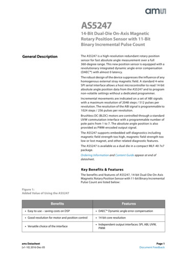
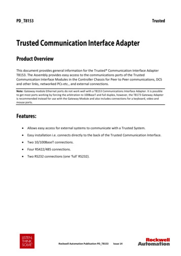
ST33TPM12SPIDescription8VHU 5200385 0 50 6HFXU&RUH 6& &38((3520Figure 1. ST33TPM12SPI hardware block diagram&RGH 'DWD 6LJQDWXUH('(6 FFHO HUDWRU5 067 520%RRW VRIWZDUH6HFXULW\0RQLWRU LQJ DQG&RQWURO1(6 &5 375 067 520 )LUHZDOO % 3% ,QWHUQDO %XV&ORFN*HQHUDWRU0RGXOH, 2 %XIIHU&5&0RGXOH7KUHH ELWWLPHUV7,6 (QJLQH7UXH 5DQGRP1XPEHU*HQHUDWRU63,DocID023143 Rev 233730,546&/.0,62026,6673067%5(6(70XOWLSOH[HG , 2V06 9 3/13
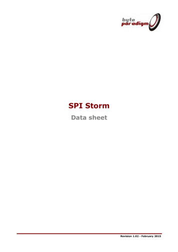
Pin and signal descriptionST33TPM12SPI2Pin and signal description2.1Pinout descriptionsFigure 2. TSSOP28 NCNCMOSINCNCVPSFigure 3. VQFN32 pinoutGNDNCNCPPNCNCVPSGND1234567832 31 30 29 28 27 26 2524 MISO23 SS22 SCLK21 NCQFN3220 NC19 GND18 NC17 NC9 10 11 12 13 14 15 16NCRESETDocID023143 Rev 2NCNCNCNCNCNC4/13
ST33TPM12SPIPin and signal descriptionTable 1. Pin descriptionsSignalTypeDescriptionVPSInput3.3V Power supply. This pin must be connected to 3.3V DC power railsupplied by the motherboard.GNDInputGND has to be connected to the main motherboard ground.TPMSTBInputPower Down indicates that the peripheral should prepare for power to beremoved from the interface devices. Actual power removal is systemdependent.RESETInputReset used to re-initialize the deviceMISOSPI Master Input, Slave Output (output from slave)MOSISPI Master Output, Slave Input (output from master)SLCKSPI Serial Clock (output from master)SSSPI Slave Select (active low; output from master)PPTPMIRQInputPhysical Presence, active high, internal pull-down. Used to indicatePhysical Presence to the TPM.Output TPM IRQ is used by TPM to handle interrupt support.DocID023143 Rev 25/13
Package mechanical data3ST33TPM12SPIPackage mechanical dataIn order to meet environmental requirements, ST offers these devices in different grades ofECOPACK packages, depending on their level of environmental compliance. ECOPACK specifications, grade definitions and product status are available at: www.st.com.ECOPACK is an ST trademark.3.128-pin thin shrink small outline package (TSSOP) with 4.4mm body widthDimensional features of the TSSOP28 package: Body width 4.4 mm. Pitch 0.65 mm.Unless otherwise specified, general tolerance is 0.1 mm.Figure 4. 28-lead thin shrink small outline package outline' F( ( N / / DDDHE 0B0(Table 2. 28-lead thin shrink small outline package mechanical .500.1700.1730.1771.00DocID023143 Rev 20.0060.0400.041
ST33TPM12SPIPackage mechanical dataTable 2. 28-lead thin shrink small outline package mechanical data .0.650.45L1kTyp.0.60Max.0.0260.750.0181.000 Typ.0.0240.02300.0408 0.10DocID023143 Rev 20 8 0.0047/13
Package mechanical data3.2ST33TPM12SPI32-lead very thin fine pitch quad flat pack no-lead (VFQFPN)packageFigure 5. VFQFPN32 5x5 mm 0.5 mm pitch package outline6HDWLQJ SODQH&GGG & 'H ( (E / 3LQ ,'5 ' /%RWWRP YLHZ B0(Table 3. VFQFPN32 5x5 mm package mechanical datainches 3.5003.6003.7000.13780.14170.1457DocID023143 Rev 2
ST33TPM12SPIPackage mechanical dataTable 3. VFQFPN32 5x5 mm package mechanical datainches 0.0500.01570.01970.00201. Values in inches are converted from mm and rounded to 4 decimal digits.DocID023143 Rev 29/13
Delivery packing4ST33TPM12SPIDelivery packingSurface-mount packages can be supplied with Tape and Reel packing. The reels have a 13"typical diameter.Reels are in plastic, either anti-static or conductive, with a black conductive cavity tape. Thecover tape is transparent anti-static or conductive.The devices are positioned in the cavities with the identifying pin (normally Pin “1”) on thesame side as the sprocket holes in the tape.The STMicroelectronics Tape & Reel specifications are compliant to the EIA 481-A standardspecification.Table 4. Packages on Tape and ReelPackageDescriptionTape widthTape pitchReel diameterQuantity per reelTSSOP 28Thin shrink smalloutline package16 mm8 mm13 in.2500VFQFPN 32Very thin fine pitchquad flat pack nolead package12 mm8 mm13 in.3000Figure 6. Reel diagram4"!.# '!) Table 5. Reel dimensionsReel size13”10/13Tapewidth1612A Max.B Min.CD Min.3301.513 0.220.2DocID023143 Rev 2G Max.16.4 2/–012.6N Min.100T Max.22.418.4Unitmm
ST33TPM12SPIDelivery packingFigure 7. Embossed carrier tape for VFQFPN 5x5 mm3 3 ( 7'' ):% . 3 6HFWLRQ 8VHU GLUHFWLRQ RI IHHG , 9 1. Drawing is not to scale.Table 6. Carrier tape dimensions for VFQFPN 5x5 mmPackageA0B0K0D1Min.PP2DP0EFWTMax.UnitFPN 5x55.25 0.15.25 0.11.1 0.11.58 0.12 0.11.55 0.054 0.11.75 0.15.5 0.112 0.30.3 0.05mmFigure 8. Embossed carrier tape for TSSOP 16 mm3R.73 '7RS&RYHU7DSH( R%R% ):%R.R3' 8VHU GLUHFWLRQ RI IHHG , 9 1. Drawing is not to scale.Table 7. Carrier tape constant dimensions for TSSOP 16 mm tapeTape sizeAo, Bo, Ko(1)DEPoT Max.Unit16 mmSee note.1.5 0.1 / -01.75 0.14 0.10.4mm1. Ao, Bo, Ko, are determined by components sizes. The clearance between the component and the cavity must be within0.05 mm (Min.) to 0.90 mm (Max.)DocID023143 Rev 211/13
Revision historyST33TPM12SPIRevision historyTable 8. Document revision history12/13DateRevisionChanges23-Apr-20121Initial release.07-Nov-20132Updated logo information on page 2.DocID023143 Rev 2
ST33TPM12SPIPlease Read Carefully:Information in this document is provided solely in connection with ST products. STMicroelectronics NV and its subsidiaries (“ST”) reserve theright to make changes, corrections, modifications or improvements, to this document, and the products and services described herein at anytime, without notice.All ST products are sold pursuant to ST’s terms and conditions of sale.Purchasers are solely responsible for the choice, selection and use of the ST products and services described herein, and ST assumes noliability whatsoever relating to the choice, selection or use of the ST products and services described herein.No license, express or implied, by estoppel or otherwise, to any intellectual property rights is granted under this document. If any part of thisdocument refers to any third party products or services it shall not be deemed a license grant by ST for the use of such third party productsor services, or any intellectual property contained therein or considered as a warranty covering the use in any manner whatsoever of suchthird party products or services or any intellectual property contained therein.UNLESS OTHERWISE SET FORTH IN ST’S TERMS AND CONDITIONS OF SALE ST DISCLAIMS ANY EXPRESS OR IMPLIEDWARRANTY WITH RESPECT TO THE USE AND/OR SALE OF ST PRODUCTS INCLUDING WITHOUT LIMITATION IMPLIEDWARRANTIES OF MERCHANTABILITY, FITNESS FOR A PARTICULAR PURPOSE (AND THEIR EQUIVALENTS UNDER THE LAWSOF ANY JURISDICTION), OR INFRINGEMENT OF ANY PATENT, COPYRIGHT OR OTHER INTELLECTUAL PROPERTY RIGHT.ST PRODUCTS ARE NOT DESIGNED OR AUTHORIZED FOR USE IN: (A) SAFETY CRITICAL APPLICATIONS SUCH AS LIFESUPPORTING, ACTIVE IMPLANTED DEVICES OR SYSTEMS WITH PRODUCT FUNCTIONAL SAFETY REQUIREMENTS; (B)AERONAUTIC APPLICATIONS; (C) AUTOMOTIVE APPLICATIONS OR ENVIRONMENTS, AND/OR (D) AEROSPACE APPLICATIONSOR ENVIRONMENTS. WHERE ST PRODUCTS ARE NOT DESIGNED FOR SUCH USE, THE PURCHASER SHALL USE PRODUCTS ATPURCHASER’S SOLE RISK, EVEN IF ST HAS BEEN INFORMED IN WRITING OF SUCH USAGE, UNLESS A PRODUCT ISEXPRESSLY DESIGNATED BY ST AS BEING INTENDED FOR “AUTOMOTIVE, AUTOMOTIVE SAFETY OR MEDICAL” INDUSTRYDOMAINS ACCORDING TO ST PRODUCT DESIGN SPECIFICATIONS. PRODUCTS FORMALLY ESCC, QML OR JAN QUALIFIED AREDEEMED SUITABLE FOR USE IN AEROSPACE BY THE CORRESPONDING GOVERNMENTAL AGENCY.Resale of ST products with provisions different from the statements and/or technical features set forth in this document shall immediately voidany warranty granted by ST for the ST product or service described herein and shall not create or extend in any manner whatsoever, anyliability of ST.ST and the ST logo are trademarks or registered trademarks of ST in various countries.Information in this document supersedes and replaces all information previously supplied.The ST logo is a registered trademark of STMicroelectronics. All other names are the property of their respective owners. 2013 STMicroelectronics - All rights reservedSTMicroelectronics group of companiesAustralia - Belgium - Brazil - Canada - China - Czech Republic - Finland - France - Germany - Hong Kong - India - Israel - Italy - Japan Malaysia - Malta - Morocco - Philippines - Singapore - Spain - Sweden - Switzerland - United Kingdom - United States of Americawww.st.comDocID023143 Rev 213/1313
Single-chip Trusted Platform Module (TPM) Compliant with Trusted Computing Group (TCG) Trusted Platform Module (TPM) Main specifications 1.2, Level 2, Revision 116, Based on TCG PC Client Specific TPM Interface Specifications 1.21, Fully based on the Common criteria (CC) EAL4 certified LPC version ST33TPM12LPC, SPI support up to 10 MHz,


![[MS-TPMVSC]: Trusted Platform Module (TPM) Virtual Smart Card .](/img/62/5bms-tpmvsc-5d-210407.jpg)
