Transcription
500W SeriesQuickReference
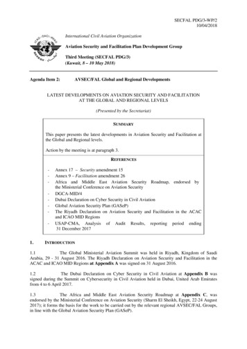
2006-2012 Garmin Ltd. or its subsidiariesThis manual reflects the operation of Main System Software version 2.00, 3.00, 4.00, 5.00, or later. Some differences in operation may be observed when comparing theinformation in this manual to earlier or later software version.All rights reserved. Except as expressly provided herein, no part of this manual may be reproduced, copied, transmitted, disseminated, downloaded or stored in anystorage medium, for any purpose without the express prior written consent of Garmin. Garmin hereby grants permission to download a single copy of this manual onto ahard drive or other electronic storage medium to be viewed and to print one copy of this manual or of any revision hereto, provided that such electronic or printed copyof this manual must contain the complete text of this copyright notice and provided further that any unauthorized commercial distribution of this manual or any revisionhereto is strictly prohibited.Information in this document is subject to change without notice. Garmin reserves the right to change or improve its products and to make changes in the contentwithout obligation to notify any person or organization of such changes or improvements. Visit the Garmin Web site (www.garmin.com or https://fly.garmin.com/flygarmin) for current updates and supplemental information concerning the use and operation of this and other Garmin products.Garmin , GPSMAP , AutoLocate , TracBack , Apollo, SafeTaxi , FliteChart , and MapSource are registered trademarks of Garmin Ltd. or its subsidiaries and maynot be used without the express permission of Garmin. NavData is a trademark of Jeppesen, Inc.; XM is a registered trademark of XM Satellite Radio, Inc.September 2012Part Number 190-00357-01 Rev GGraphic MovingMap Display andNavigation InfoNav FreqWindowComm FreqWindowPrinted in the USAPhotocell forAuto-DimmingRange KeysComm FreqFlip/FlopDirect-To KeyPower and CommVolume/SquelchMenu KeyNav Radio Freq Flip/FlopClear KeyEnter KeyNav RadioVolumeWaypoint andarrival alerts, turnadvisories, function,and page numberTerrain, FlightPhase, andGPS IntegrityAnnunciatorLarge KnobLarge KnobComm/VLOCFreq (MHz)Small KnobComm/VLOCFreq (kHz)Small Knob(Cursor - Press toactivate)NavigationSource: GPS,VLOC, orGPS-PTKCDIKeyAviationDatabaseCardOBSKeyProcedure KeyCamLockMessageKeyFlight PlanKeyTerrain Database Card
WARNINGS, CAUTIONS, and NOTESWARNING: The altitude calculated by the 500W-seriesis geometric height above mean sea level and could varysignif icantly from altitude displayed by pressure altimeters inaircraft.WARNING: The Jeppesen database incorporated in the500W-series must be updated regularly in order to ensurethat its information is current. Updates are released every28 days. A database information packet is included in your500W-series package. Pilots using an out-of-date databasedo so entirely at their own risk!WARNING: VNAV is to be used for advisory purposes only.VNAV messages or vertical speed required should not beused to maintain terrain or ATC clearances. Terrain and ATCclearances are the sole responsibility of the pilot.WARNING: Do not use data link weather information formaneuvering in, near, or around areas of hazardous weather.Information contained within data link weather products maynot accurately depict current weather conditions.WARNING: Do not use the indicated data link weatherproduct age to determine the age of the weather informationshown by the data link weather product. Due to time delaysinherent in gathering and processing weather data for datalink transmission, the weather information shown by thedata link weather product may be significantly older than theindicated weather product age.CAUTION: The Global Positioning System is operated by theUnited States government, which is solely responsible for itsaccuracy and maintenance. The system is subject to changeswhich could affect the accuracy and performance of all GPSequipment. Although the Garmin 500W-series are precisionelectronic NAVigation AIDs (NAVAID), any NAVAID can bemisused or misinterpreted and therefore become unsafe.CAUTION: Use the 500W-series at your own risk. To reduce therisk of unsafe operation, carefully review and understand allaspects of this Owner’s Manual and the Flight Manual Supplement, and thoroughly practice basic operation prior to actualuse. When in actual use, carefully compare indications from the500W-series to all available navigation sources, including theinformation from other NAVAIDS, visual sightings, charts, etc.For safety, always resolve any discrepancies before continuingnavigation.receiver may create electromagnetic interference (EMI) whichmay affect the ability of the GPS receiver to receive anddecode the satellite signals. In such event, the interferencemay be reduced or eliminated by switching off the source ofinterference or moving the GPS receiver away from it.CAUTION: The electronic chart is an aid to navigation andis designed to facilitate the use of authorized governmentcharts, not replace them. Land and water data is providedonly as a general reference to your surroundings. The positional accuracy of the land and water data is not of a precision suitable for use in navigation and it should not be usedfor navigation. Only official government charts and noticescontain all information needed for safe navigation – and, asalways, the user is responsible for their prudent use.CAUTION: The Terrain feature (in units not equipped withTAWS) is for supplemental awareness only. The pilot/crewis responsible for all terrain and obstacle avoidance usinginformation not provided by the 500W-series Terrain feature.CAUTION: The Garmin 500W-series does not contain anyuser-serviceable parts. Repairs should only be made by anauthorized Garmin service center. Unauthorized repairs ormodifications could void your warranty and authority tooperate this device under FCC Part 15 regulations.NOTE: The GNS 500W-series units use a different databasethan in the legacy units. The databases are incompatible between units. The GNS 500W-series units must use a WAASenabled database.NOTE: This product, its packaging, and its componentscontain chemicals known to the State of California to causecancer, birth defects, or reproductive harm. This notice is being provided in accordance with California’s Proposition 65. Ifyou have any questions or would like additional information,please refer to our website at www.garmin.com/prop65.NOTE: It is the pilot’s responsibility for initial missed approach guidance in accordance with published procedure. Theunit may not provide correct guidance until established on adefined leg.NOTE: GPS level of service annunciations (LPV, ENR, etc.)are not applicable to the external CDI (or HSI) when VLOC isactive.CAUTION: GPS receivers operate by receiving and decoding very low power radio signals broadcast by satellites. Itis possible that in some situations other radio equipmentor electronic equipment used in close proximity to a GPS190-00357-01 Rev G1
MODEL DESCRIPTIONSModel DescriptionsThis guide covers the operation of the GNS 530W, GNS530AW, and the GPS 500W. In general, all models will bereferred to as the 500W-series, except where there are physical or operational differences. The 500W-series units are 6.25”wide and 4.60” high. The display is a 320 by 234 pixel colorLCD. The units include two removable data cards, one witha Jeppesen aviation database (inserted in the left-most cardslot) and the second is a Terrain database (inserted in theright-most card slot).GPS 500WThe GPS 500W is a GPS-only unit with a WAAS GPSengine and is TSO C146a certified for en route, terminal,precision, and non-precision approaches. The GPS 500Wcan simultaneously give aviators vital approach information and weather and traffic data in relation to theirposition on a large, color moving map display. Thanks toa high-contrast color display, the information can be easilyread from wide viewing angles even in direct sunlight.Its color moving map features a built-in database thatshows cities, highways, railroads, rivers, lakes, coastlines,and a complete Jeppesen aviation database. The Jeppesendatabase (that can be updated with a front-loading datacard) contains all airports, VORs, NDBs, Intersections, FSS,Approach, DPs/STARs and SUA information. The obstacleand terrain databases provide an aid to navigation to helpyou work with approved navigation charts.nect to XM Satellite Radio’s XM WX Weather Service via theGDL 69 datalink receiver plus XM Audio with theGDL 69A.GNS 530W and GNS 530AWThe GNS 530W and GNS 530AW include all of thefeatures of the GPS 500W, and also include an IFR certifiedairborne VHF communications transceiver and IFR certified airborne VOR/Localizer and Glideslope receivers. Thismulti-purpose unit is available with either a 10-watt (GNS530W) or 16-watt (GNS 530AW) Com transceiver. References to the GNS 530W also include the GNS 530AW.Helicopter InstallationsIn Helicopter installations, the ownship icon is set toa helicopter. When present, HTAWS will be used insteadof TAWS. See the Garmin Optional Displays Pilot’s GuideAddendum P/N 190-00356-30 Rev G, or later, for HTAWSinformation.Pilots will enjoy the GPS 500W as an Multi-FunctionDisplay (MFD), especially when it is coupled with traffic, lightning detection, and weather interfaces like RyanTCAD, TIS from the Garmin GTX 330 Mode S transponder,L3 SKYWATCH , or STORMSCOPE WX 500. With theFault Detection and Exclusion (FDE) prediction programincluded with the Trainer CD, the GPS 500W may be usedfor oceanic or remote operations. For the latest in graphicaland textual weather information, the GPS 500W can con2190-00357-01 Rev G
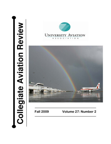
KEYS AND KNOBSLeft-hand Keys and KnobskThe COM power/volume knob controls unit power and, in theGNS 530W, communications radio volume. Press momentarily todisable automatic squelch control. Turn clockwise to turn the uniton.jIn the GNS 530W, the VLOC volume knob controls audio volumefor the selected VOR/ Localizer frequency. Press momentarily toenable/disable the ident tone.yIn the GNS 530W, the large left knob (COM/VLOC) is used totune the megahertz (MHz) value of the standby frequency for thecommunications transceiver (COM) or the VOR/Localizer receiver,whichever is currently selected by the tuning cursor.vIn the GNS 530W, the small left knob (PUSH C/V) is used to tunethe kilohertz (kHz) value of the standby frequency for the communications transceiver (COM) or the VLOC receiver, whicheveris currently selected by the tuning cursor. Press this knob momentarily to toggle the tuning cursor between the COM and VLOCfrequency fields.WIn the GNS 530W, the COM flip-flop key is used to swap theactive and standby COM frequencies. Press and hold to select theemergency channel (121.500 MHz).VIn the GNS 530W, the VLOC flip-flop key is used to swap theactive and standby VLOC frequencies(i.e., make the selected standby frequency active).190-00357-01 Rev GGPS 500WGNS 530WOn the GNS 530W, the large and small left knobsallow you to tune the desired COM or VLOCfrequency.3
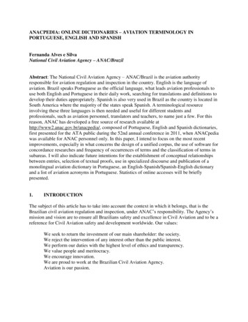
KEYS AND KNOBSRight-hand Keys and KnobsRNGThe range key (RNG) allows you to select the desired map scale. Press theup arrow to zoom out to a larger area, or the down arrow to zoom in to asmaller area.direct-to key provides access to the direct-to function, which allowsD Theyou to enter a destination waypoint and establishes a direct course (singleleg flight plan) to the selected destination.menu key (MENU) displays a context-sensitive list of options. Thism Theoptions list allows you to access additional features or make settings changeswhich relate to the currently displayed page.clear key (CLR) is used to erase information or cancel an entry. Pressc Theand hold this key to immediately display the Default Navigation Page,regardless of which page is currently displayed.enter key (ENT) is used to approve an operation or complete dataE Theentry. It is also used to confirm information, such as the Database PageData is entered using the large andsmall right knobs. Experiment withthem to become efficient at enteringdata. This greatly reduces the amount oftime spent operating the 500W-seriesunit in flight.4during power on.tThe large right knob (GPS) is used to select between the various pagegroups: NAV, WPT, AUX or NRST. With the on-screen cursor enabled, thelarge right knob allows you to move the cursor about the page.rThe small right knob (PUSH CRSR) is used to select between the variouspages within one of the groups listed above. Press this knob momentarilyto display the on-screen cursor. The cursor allows you to enter data and/ormake a selection from a list of options.190-00357-01 Rev G
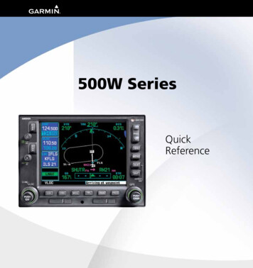
KEYSGPS 500WGNS 530WBottom Row KeysNCOThe nearest (NRST) key (GPS 500W)displays the Nearest Airports page. Then,turning the small right knob steps throughthe NRST pages.The course deviation indicator (CDI) key(GNS 530W) is used to toggle the navigationsource (GPS or VLOC) that provides outputto an external HSI or CDI.MThe message (MSG) key is used to viewsystem messages, important warnings, andrequirements.FThe flight plan (FPL) key allows you tocreate, edit, activate and invert flight plans,as well as access approaches, departures andarrivals. A closest-point-to-flight-plan featureis also available from the flight plan key.VNAVThe omni-bearing selector (OBS) key isused for two functions: to activate OBS selection and as a suspend key.As a Suspend key, it is used to select manualor automatic sequencing of waypoints.Pressing this key selects SUSP mode, whichretains the current “active to” waypoint asyour navigation reference even after passingthe waypoint (i.e., prevents sequencing to thenext waypoint). Pressing the OBS key againreturns to normal operation, with automaticsequencing of waypoints.PThe vertical navigation (VNAV) key allowsyou to create a three-dimensional profilewhich guides you to a final (target) altitude ata specified location.The procedures (PROC) key allows you toselect approaches, departures and arrivalsfrom your flight plan. When using a flightplan, available procedures for your departureand/or arrival airport are offered automatically. Otherwise, you may select the desiredairport, then the desired procedure.Whenever OBS mode is selected, you may setthe desired course to/from a waypoint usingthe OBS Page, or an external OBS selector onyour HSI or CDI.190-00357-01 Rev G5
POWER ONPowering Up1.Turn the COM power/volume knob clockwise toturn the unit on and set the desired radio volume.2.The Main and GPS software version page appearsbriefly, followed by land and terrain database pages,as the unit conducts self-tests to ensure properoperation.3.Once the self-test concludes, database confirmation pages are displayed, showing the effective andexpiration dates of the databases on the NavData card. Press the ENT key to acknowledge the lastdatabase page and proceed to the instrument panelself-test page. There may be more self-test screensdepending on optional equipment installed in youraircraft.4.The instrument panel self-test page allows you toverify that the unit is communicating properly within-panel instruments. Compare on-screen indications with the information depicted on connectedinstruments, such as the CDI, HSI, RMI and/or external annunciators. Once you have verified properoperation, turn the large right knob to select"Set Full Fuel?", "Go To Checklist", or "OK?" (todisplay the Satellite Status Page), and then pressthe ENT key. Other pages may exist depending onthe installation of optional features.5.When the GPS receiver has acquired a sufficientnumber of satellites to determine a position, theMap Page is automatically displayed showing yourpresent position.Power-up Sequence6190-00357-01 Rev G
SCREEN LAYOUT/CURSORS/FREQ SELECTION/DATA ENTRYScreen Layout (windows)The display is divided into four separate “windows” (orscreen areas). In the GNS 530W, the left 1/4 of the display provides a COM window (top two lines), a VLOC window, a selectable window (by default with VOR ident/radial, but selectablefor other data), and a three line annunciator window. The right3/4 of the display consists of a GPS window, which is whereyou’ll find the various navigation, waypoint information andsettings “pages”. The three lines in the bottom left window ofthe display are used for terrain, flight phase, and GPS integrityannunciators.COM WindowVLOC WindowActive Frequency on top & Standbyon bottom (highlighted by cursor)VLOC Ident Window(user-selectable; can alsodisplay traffic or other data)Terrain AnnunciatorFlight Phase AnnunciatorGPS Integrity AnnunciatorGPSWindowEach unique screen of information is referred to as a “page.”Pages are typically selected using the small and large rightknobs—with the cursor removed from the GPS window.CursorsThere are two separate cursors: a tuning cursor and a GPSwindow cursor. The tuning cursor is used to select the standbyCOM or VLOC frequency. Pushing the small left knob movesthe tuning cursor back-and-forth between the COM and VLOCfrequency windows. To set a new active frequency, you mustfirst enter the frequency in the standby field, then use the COMor VLOC flip-flop key to activate the new frequency. Push inon the small right knob and then turn the large right knob tomove the GPS window cursor around the page.Frequency Selection (530W only)1. If the tuning cursor is not currently inthe desired window (COM or VLOC),press the small left knob momentarilyto switch the highlight between theCOM and VLOC windows. Adjustingthe frequencies with the large andsmall left knobs will affect the standbyfrequency.2. Turn the large left knob to select thedesired megahertz (MHz) value. Forexample, the “117” portion of the frequency “117.70”.3. Turn the small left knob to select thedesired kilohertz (kHz) value. For example, the “.70” portion of the frequency“117.70”.4. To activate the selected frequency, pressthe appropriate flip-flop key—COM for communicationfrequencies or VLOC for VOR/Localizer frequencies.To Quickly Tune and Activate the 121.500 Emergency Channel1. In the GNS 530W, press and hold the COM flipflop key for approximately two seconds.Data EntryData is entered in theGPS window using thesmall and large rightknobs. The large right knobis used to move the cursorbetween fields. The smallright knob is used to selectindividual characters at thehighlighted cursor location.For example, to change the“N” in the illustration atright to a different character, turn the small right knob.190-00357-01 Rev G7
PAGE SELECTION(Small right knob to select pages within the group)NAV GroupDefault NAVMapNAVCOMTerrainSatellite StatusFive, or more, NAV pages are availablewhen the unit’s installation includesconnection to traffic and/or weatherinformation sources.(Large right knob to change page groups)WPT GroupAirport Location Airport Runway Airport Frequency Airport ApproachVORNDBAirport ArrivalUtilityIntersectionSelection of any main page is performed usingthe large and small right knobs. When the GPSwindow cursor is off, the large right knob selectsthe page group: NAV, WPT, AUX or NRST. The smallright knob selects the desired page within a group.To quickly select the Default NAV Page, press andhold the CLR key.User WaypointAUX GroupFlight PlanningAirport DepartureSetup 1Setup 2Nearest NDBNearest VORNRST GroupNearest Airport Nearest IntersectionNearest User WptNearest CenterNearest FSSNearest AirspaceFPL GroupVNAVPROCActive Flight Plan Flight Plan CatalogVertical NavigationProceduresSelection of these pages is made by pressing the FPL, VNAV or PROC keys.8190-00357-01 Rev G
DEFAULT NAV PAGE / ANNUNCIATORSDefault NAV PageActive Leg ofFlight Plan, orDirect-to DestinationTo Select a Different Data Item for any Data Field1. With the Default NAV Page displayed, press theMENU key to display an options menu.User-selectableData Fields(all four corners)2.3.To/FromFlagTurn the large right knob to highlight the “ChangeFields?” option, and press ENT to select thisoption.Use the large right knob to highlight the datafield you wish to change.Course DeviationIndicator (CDI)The following symbols are used (directly above theCDI) to depict the active leg of a flight plan or direct-to:Course to a Waypoint, or Desired Course between Two WaypointsDirect-To a WaypointVectors-To-FinalLeft-hand Holding PatternLeft Procedure TurnRight-hand Holding PatternRight Procedure TurnDME Arc to the leftDME Arc to the rightTo Quickly Display the Default NAV Page1. From any page, press and hold CLR for approximately two seconds.4.5.6.Turn the small right knob to display a list of available data items. Continue turning the small rightknob to select the desired data item from the list.Press ENT to select the desired data item and returnto the Default NAV Page.Press the small right knob to remove the cursorfrom the page.Bottom Row Annunciators and MessagesTerrain annunciations:Ter Test, Ter N/A, Terrain, Ter INHB,and TER FailCDI/RAIM Mode: Approach (LNAV,L/VNAV, LNAV V, or LPV ), Oceanic (OCN), Terminal (TERM), EnRoute (ENR) or “0.30” (if the CDI ismanually set to "0.30" and not flying an approach). Annunciations notapplicable to the external CDI whenVLOC is active.GPS Integrity FailureMessage Annunciator: Flashing (new message), On, or blank (no message)Navigation Source:GPS, VLOC, or GPS-PTKOBS Mode: Suspend(SUSP), OBS or blank (forauto-sequencing)190-00357-01 Rev GPage Annunciator (NAV/WPT/AUX/NRST/FPL/VNAV/PROC), WaypointAlert (“Next DTK”), Turn Advisory(“Left to xxxº”), etc.9
MAP PAGEMap PageTo Turn the Data Fields On Along the Right-handSide of the Map Page(Optional) Data Fields can appear on theright-hand side of the pageMap Display1.With the Map Page displayed, press MENU todisplay an options menu.2.Turn the large right knob to highlight “Data FieldsOn?”, then press ENT.3.To return to a full-screen map display, follow steps1 and 2, but instead select “Data Fields Off?” fromthe options menu.Map ScaleTo Select a Different Data Item for any Data FieldPresent PositionThe following symbols are used to depict the various airports and navaids on the Map Page:Airport with hard surface runway(s); Primary runway shownAirport with soft surface runway(s) onlyPrivate alizerLocator Outer Marker1.With the Map Page displayed, press the MENU keyto display an options menu.2.Turn the large right knob to highlight the “ChangeFields?” option and then press ENT.3.Turn the large right knob to highlight the datafield you wish to change.4.Turn the small right knob to display a list of available data items. Continue turning the small rightknob to select the desired data item from the list.5.Press ENT to select the desired data item and returnto the Map Page.6.Press the small right knob to remove the cursorfrom the page.HeliportTo Select a Map Scale1. Press the up arrow on the RNG key to zoom out toa larger map area.2. Press the down arrow on the RNG key to zoom into a smaller map area with more detail.To Quickly Declutter the Map DisplayThe 500W series supports four levels of map decluttering.1. Press the CLR key momentarily to change theamount of map detail. The declutter level willappear adjacent to the map scale.2. Press the CLR key as needed to select the desiredamount of map detail.10190-00357-01 Rev G
NAVCOM PAGE / TERRAIN PAGENAVCOM PageThe NAVCOM Page provides a list of the airport communication and navigation frequencies at your departure, en routeand arrival airports.Departure,En Route,or ormationScrollBarAssignedFrequencyTo Select a Frequency List for a Departure, En Route,or Arrival Airport1. Press the small right knob to activate thecursor.2. Turn the large right knob to place the cursor onthe airport identifier field (top line on the NAVCOMPage).3. Turn the small right knob to select the desiredairport and press ENT.Obstacle SymbolTo Scroll Through the List of Frequencies1. Activate the cursor, if not already active, by pressingthe small right knob.2. Turn the large right knob to move the cursorthrough the list of frequencies. If there are morefrequencies in the list than can be displayed onUnlighted Obstacle 1000’ AGL 1000’ AGLthe screen, a scroll bar along the right-hand sideof the screen will indicate which part of the list iscurrently being displayed.Auto-Tuning a Frequency from the NAVCOM Page1. In the GNS 530W, highlight the desired frequencyby scrolling through the list of frequencies, asdescribed in the previous procedure.2. To place a frequency in the standby field of theCOM or VLOC window, highlight the desired frequency and press ENT.Terrain PageTo display the TERRAIN Page, select the NAV group andturn the small right knob until the TERRAIN Page is displayed.The page displays terrain information, aircraft ground track, andGPS-derived MSL altitude (GSL altitude). Altitude is shown inincrements of 20 feet or in increments of 10 meters, dependingon unit configuration.For units with TAWS or installed in helicopters or equippedwith optional HTAWS, refer to 400W/500W Series GarminOptional Displays, P/N 190-00356-30 Rev G, or later.To inhibit TERRAIN:Select the TERRAIN Page and press MENU. “InhibitTerrain?” is selected by default.Press ENT. The TERRAIN system is inhibited. Theannunciation is displayed in the terrainannunciator field whenever terrain is inhibited.1.2.Lighted Obstacle 1000’ AGL 1000’ e above or within 100 ft belowcurrent aircraft altitudeYellowTerrain/Obstacle between 100 ft and 1000 ftbelow the aircraft altitudeTerrain Color Symbology190-00357-01 Rev G11
AIRPORT INFORMATIONViewing Airport Information1. From any page, press and hold the CLR key todisplay the Default NAV Page. (You may skip thisstep if you are already viewing any of the main GPSpages.)2.Turn the large right knob to select the WPT pagegroup. “WPT” will appear in the lower right cornerof the screen.3.Turn the small right knob to select the desiredWPT page. Airport information is displayed on thefirst six WPT pages: airport location, airport runway,airport frequency, airport approach, airport arrivaland airport departure.4.Press the small right knob to activate thecursor.5.Use the small and large right knobs to enter theidentifier of the desired airport.6.Once the identifier is entered, the information forthat airport will appear on the page. Press ENT toaccept the selected identifier.7.To view the other airport information pages, pressthe small right knob to remove the cursor, thenturn the small right knob to select the desiredpage.Viewing Airport Information by Facility Name orCity121.Select the Airport Location Page.2.Press the small right knob to activate the onscreen cursor.3.Turn the large right knob to highlight the facilityname (second line) or the city (third line) field.4.Use the small and large right knobs to enterthe facility name or city location of the desiredairport. As you spell the facility name or city, theSpell’N’Find feature will select the first entry inthe database based upon the characters you haveentered up to that point.5.Once the name is entered, the information for thatairport will appear on the page. Press ENT to acceptthe selected airport.6.To view the other airport information pages, pressthe small right knob to remove the cursor, thenturn the small right knob to select the desiredpage.Auto-Tuning a Frequency from a ListThe GNS 530W’s auto-tune feature allows you to quicklyselect any displayed database frequency as your standby frequency. With a minimum of keystrokes, any frequency listed onthe Airport Frequency Page can be transferred to the standbyfield of the COM or VLOC window. The Airport Frequency pagein the GPS 500W allows you to view frequency information andscroll through the list by turning the large right knob.1.Select the Airport Frequencies Page from the WPTpage group.2.Press the small right knob to activate the cursoron the airport identifier field.3.Use the small and large right knobs to enter theidentifier of the desired airport. Press ENT whenfinished.4.Turn the large right knob to highlight the desiredfrequency.5.Press ENT to place the highlighted frequency inthe standby field of the COM or VLOC window (asappropriate).6.To activate the selected frequency, press the COMor VLOC flip-flop key (as appropriate).190-00357-01 Rev G
DIRECT-TO NAVIGATIONTo Select a Direct-To Destination1.Press the direct-to key. A Select Direct To Waypointpage will appear, with the waypoint identifier fieldhighlighted.2.Use the small and large right knobs to enter theidentifier of the desired destination waypoint.3.Press ENT to confirm the selected waypoint. PressENT again to activate the direct-to function.To Select a Direct-To Destination from the MapPage1.Select the Map Page from the main page group.2.Press the small right knob to display a panningpointer.3.Turn the small and large right knobs to placethe panning pointer at the desired destinationlocation.4.If the panning pointer is placed on an existing airport, navaid or user waypoint, the waypoint namewill be highlighted. Press the direct-to key, thenthe ENT key (twice) to navigate to the waypoint.5.If the panning pointer is placed in an open location, press the direct-to key, then ENT (twice) tocreate a waypoint at the pointer location (named“ MAP”) and navigate to it.To Select a Direct-To Destination by FacilityName or Citytion waypoint. As you spell the facility name or city,the Spell’N’Find feature will select the first entry inthe database based upon the characters you haveentered up to that point.4.Continue turning the small right knob to scrollthrough any additional database listings for theselected facility name or city. You can also scrollbackwards with the small right knob if you scrollpast the desired waypoint.5.Press ENT to confirm the selected waypoint. PressENT again to activate the direct-to function.To Se
WARNING: Do not use data link weather information for maneuvering in, near, or around areas of hazardous weather. . a Jeppesen aviation database (inserted in the left-most card slot) and the second is a Terrain database (inserted in the right-most card slot). GPS 500W