Transcription
WORLD-BEAM QS30H2O SeriesHigh-Power Water SensorFor the latest technical information about this product, including specifications, dimensions, and wiring, see www.BannerEngineering.comFeatures Special emitter/receiver infrared wavelength tuned to the absorption band of water Powerful enough to burn through many types of plastic and glass containers Water-based liquids will attenuate the signal; this enhances contrast on difficultsensing applications found on bottle-filling lines Excellent noise immunity and crosstalk avoidance Easy-to-read operating status indicators Bipolar discrete outputs, PNP and NPN; analog model also available Light Operate and Dark Operate models available Models available with 2 m or 9 m (6.5' or 30') cable, or 150 mm (6") pigtail withquick-disconnect fitting Rugged IP67 (NEMA 6) housing for harsh environments; 1200 psi washdown rated per NEMA PW12 Compact housing, mounting versatility — 30 mm threaded barrel- or side-mountModelsStandard Models**Model*DescriptionSensing Beamand Range†SupplyVoltage1450 nm infrared13 mm effective beam dia.QS30EXH2OEmitterQS30ARH2OReceiver, light operateQS30RRH2OReceiver, dark operateQS30ARXH2OHigh-gain receiver, light operateQS30RRXH2OHigh-gain receiver, dark operateQS30RXH2OUHigh-gain receiver, analog2 m (6.5') rangeOutput--10 to 30V dcBipolar (NPN andPNP)4 m (13') range15 to 30V dc0-10V AnalogSupplyVoltageOutputSuper High-Power Models**Model*DescriptionSensing Beamand Range†1450 nm infrared13 mm effective beam dia.QS30EXSH2OSuper high-power emitterQS30ARXSH2OSuper high-power receiver, light operateQS30RRXSH2OSuper high-power receiver, dark operate-10 to 30V dc8 m (26') rangeBipolar (NPN andPNP)* Only 2 m (6') cables are listed. For 9 m (30') cable, add suffix “W/30” to the model number (e.g., QS30EH2O W/30). For 150 mm (6.5")pigtail with a 5-pin Euro-style connector, add suffix “Q5” to the model number (e.g., QS30EH2OQ5). A model with a QDconnector requires a mating cordset (see Quick-Disconnect (QD) Cordsets on page 7).** Standard emitters will only work with standard receivers. Super High-Power emitters will only work with Super High-Power receivers.† Sensors can be used at ranges greater than listed for applications that require less excess gain. Please consult thefactory for assistance on your long-range applications.P/N 136166 rev. C10/7/20110 1361667
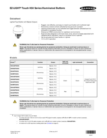
WORLD-BEAM QS30H2O SeriesWARNING: Not To Be Used for Personnel ProtectionNever use this product as a sensing device for personnel protection. Doing so could lead to serious injury or death. This product does NOT include the self-checking redundant circuitry necessary toallow its use in personnel safety applications. A sensor failure or malfunction can cause either an energized or de-energized sensor output condition.OverviewThe Banner QS30H2O series water sensor was developed to detect the presence of water. Its electro-optical components are tuned to one absorptionband of water in the long infrared spectrum. The emitted infrared light penetrates many types of plastic and glass containers, but will not pass throughwater-based fluids, nor through opaque substances such as wood, metal orcardboard. Accessory apertures are available to attenuate or shape the beamfor low-gain applications, for example, clear water in a clear bottle.Low-gain models are recommended for sensing applications where the liquidcontainer is transparent or when the thickness of liquid being detected issmall. Some examples are clear glass test tubes and clear PET beverage bottles. High-gain models are recommended when the liquid container is lightblocking (translucent) and when the thickness of liquid being detected is large.Some examples are HDPE milk containers, colored PET beverage bottles,and etched glass containers. Super High-Power models are recommended forthick, opaque containers that require maximum burn-through power at a slower response speed.For all applications, the sensors must be installed to maximize the optical contrast between the clear and blocked states. The installer can use aperturesand mechanical alignment of the sensors to achieve the best results (seepage 3). The QS30H2O sensor enhances the available contrast by taking advantage of the absorption band of water.Figure 1. Features1Emitter Power LED (Green)2Output Conducting (Yellow, Discrete Models Only)3Receiver Power LED (Green)4AID Indicator (Yellow)For advanced applications, a 0–10V analog output is available. The analog output allows the user to directly measure the amount ofsignal attenuation. The analog output value can be filtered and a switching threshold determined in a PLC or computer as required for theapplication. Please consult the factory for more information on using the analog output.Each discrete output model has two bipolar outputs that switch simultaneously: one each NPN (sinking) and PNP (sourcing). Light Operate and Dark Operate models are available.The versatile housing provides multiple mounting configurations in a minimum of space. These sensors are extremely rugged, powerfuland leakproof, with epoxy-encapsulated electronics for maximum resistance to mechanical shock and vibration. They are powerfulenough to burn through dust and many types of industrial and process contamination.The sensors’ innovative circuitry provides excellent EMI/RFI noise immunity. For applications where optical crosstalk between multiplesensor pairs may be a problem, either of two modulation frequencies may be selected. (Set each emitter to the same frequency as itsreceiver, via the sensor hookup; see Figure 2. Sensor Alignment Procedure on page 3 or Hookups on page 7.)IndicatorsEach sensor has a green Power ON/OFF indicator, visible from 360 (see Figure 1). Receivers also have a yellow AID indicator thatflashes to show signal strength. (The higher the flash rate, the more light is received; a solid AID LED indicates excellent signal.) Discretemodels also have a large yellow LED that lights when an output is conducting.Sensor ConfigurationTeaching LimitsDiscrete models require no configuration; simply align the emitter to the receiver to maximize contrast between the clear and blockedconditions (see Figure 2. Sensor Alignment Procedure on page 3).2www.bannerengineering.com - tel: 763-544-3164P/N 136166 rev. C
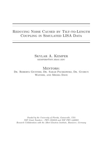
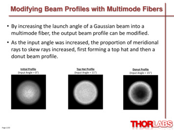
WORLD-BEAM QS30H2O SeriesFor analog models in high-contrast applications, alignment may be the only configuration needed. For more challenging applications using analog models, use the TEACH procedure to maximize contrast. This procedure is accomplished by pulsing the receiver’s white wire(see Hookups on page 7 and teach procedure on page 4). Analog output slope also can be inverted from positive to negative or back.Sensor Alignment — When Empty Container Can Be Presented1. Position both the emitter and the receiver loosely in their mounting position. See Figure 2.2. Present the “clear” condition for the application (an empty container).3. Verify that both emitter and receiver are wired for the samemodulation frequency (see below).4. Adjust the emitter first, then the receiver. Adjust the emitter’s position until the receiver AID indicator is ON steady, or is flashingat its fastest rate.5. Tighten the emitter mounting hardware, then repeat step 4 forthe receiver.6. Block the sensor beam with the target and verify that the outputchanges state.Figure 2. Sensor Alignment ProcedureSensor Alignment — When Empty Container Cannot Be PresentedFor this procedure, the clear condition is no container at all.1. Mount loosely and mechanically align the emitter and the receiver such that their faces are parallel to one another. (The AID indicator should be ON steady.)2. Rotate the emitter in one direction until the receiver AID indicator begins to flash. Repeat in the other direction. Position the emittermidway between those two positions and tighten the emitter mounting hardware.3. Repeat step 2 for the receiver.4. Block the sensor beam with the target and verify that the output changes state.Frequency SelectionThe modulation frequency (A or B) is selected by the state of the gray wire (on cabled models; pin 5 on QD models — see Hookups onpage 7). A “ ” voltage or no connection selects frequency A; connecting it to “–” selects frequency B. Each emitter must be set to thesame frequency as its receiver.Emitter InhibitTo disable (or inhibit) the emitter LED (useful for testing the receiver operation), connect the white wire to “–” voltage.Analog Static TEACHAnalog TEACH is performed remotely, by pulsing the white Teach wire (seeHookups).Restore Factory TEACH: Reverts the sensing limits to the factory default limits(max contrast); output slope is not affected.Analog Output Slope: Toggles the analog output to send a high signal whenobject is absent (positive slope) or present (negative slope). Analog slope canbe selected based on the TEACH order (first taught condition is always 0V; second taught condition is 10V) or by using the slope select procedure below. If theslope select procedure is used, it must be used after teaching the limits. To determine the current slope setting, measure the output signal during objectpresent and absent conditions.10V dcPositiveSlopeNegativeSlopeBlocked0V dcClearSignalFigure 3. Analog Static TeachP/N 136166 rev. Cwww.bannerengineering.com - tel: 763-544-31643
WORLD-BEAM QS30H2O SeriesRemote LineStepAccess TEACH Mode/Learn 1st Condition Present 1st condition. Single-pulse remote TEACH line.TLearn 2nd ConditionResult0.04 seconds T 0.8 secondsPower LED: OFFAID LED: Double-flash1x Present 2nd condition. Single-pulse remote TEACH line.T1xTEACH AcceptedPower LED: Flashes 3 times, then ONAID LED: AID mode (flash rate varies dependingupon signal strength)Sensor returns to RUN mode.TEACH Not AcceptedPower LED: OFFAID LED: Single-flashSensor returns to “Learn 1st Condition.”Restore Factory Default (Maximum Contrast) SettingRemote LineStepAccess TEACH Mode Single-pulse remote TEACH lineTRestore Factory Default Setting(Maximum Contrast Setting)Result0.04 seconds T 0.8 secondsPower LED: OFFAID LED: Double-flash1x Double-pulse remote TEACH lineTT2xTPower LED: Flashes 3 times, then ONAID LED: AID mode (flash rate varies depending upon signal strength)Sensor returns to RUN mode with maximumcontrast setting.Analog Output Slope InvertTeach sensing limits before inverting the output slope.Remote LineStepToggle Analog Output Slope Triple-pulse remote TEACH lineTTT4Result0.04 seconds T 0.8 secondsTTAnalog output slope toggles between positiveand negative.3xwww.bannerengineering.com - tel: 763-544-3164P/N 136166 rev. C
WORLD-BEAM QS30H2O SeriesSpecificationsNOTE: Specifications are subject to change without notice.Supply VoltageEmitter: 10 to 30V dc (10% maximum ripple) at less than 80 mADiscrete Receiver: 10 to 30V dc (10% maximum ripple) at less than 65 mA (exclusive of load)Analog Receiver: 15 to 30V dc (10% maximum ripple) at less than 65 mA (exclusive of load)Beam1450 nm, infrared13 mm effective beam diameterSensing RangeLow-gain models: 2 m (6.5')High-gain models: 4 m (13')Super High-Power models: 8 m (26')Output ConfigurationDiscrete models: Bi-polar current sinking (NPN) white wire; current sourcing (PNP) black wireAnalog models: 0–10V (black wire)Output RatingDiscrete models: 100 mA maximum load @ 25 COFF-state leakage current: less than 10 µAON-state saturation voltage:PNP: less than 1.2V at 10 mA; less than 2.5V at 100 mANPN: less than 200 mV at 10 mA; less than 1V at 100 mAProtected against false pulse on power-up and continuous overload or short circuitAnalog models: 2 KΩ minimum impedanceOutput ResponseDiscrete models:10x excess gain or more — Standard models: 1 ms ON and OFF response; 500 µs repeatabilitySuper High-Power models: 10 ms ON and OFF response; 5 ms repeatability2x to 10x excess gain — Standard models: 3 ms ON and OFF response; 2.5 ms repeatabilitySuper High-Power models: 30 ms ON and OFF response; 25 ms repeatabilityAnalog models: 25 ms for a 95% step changeAdjustmentsLight Operate/Dark Operate — depending on model selectedFrequency — selected via gray wireA: Gray ( )B: Gray (–)Emitter only: LED inhibit — selected via white wireWhite (–) turns emitter LED OFF (to allow verification of receiver operation)IndicatorsGreen LED on housing top: Power ONReceiver only:Yellow AID LED on housing top: Flashes to indicate signal strength (faster flash better signal)Yellow LED (large oval on housing back): Discrete output conductingEnvironmental RatingLeakproof design rated IEC IP67 (NEMA 6); PW12 1200 psi washdown per NEMA PW12ConstructionHousing: plastic (PC/ABS blend)Front window: plastic (PMMA -acrylic)Cable: PVCPigtail QD: PVC and nickel-plated brassConnection5-wire 2 m or 9 m cable (6' or 30') or 150 mm (6") pigtail with 5-pin Euro-style quick-disconnect fittingOperating ConditionsTemperature: 20 to 60 C ( 4 to 140 F)Relative Humidity: 95%; non-condensingCertificationsP/N 136166 rev. Cwww.bannerengineering.com - tel: 763-544-31645
WORLD-BEAM QS30H2O SeriesPerformance Curves1000000EXC 100000ESS 10000GAINSuperHighPowerBeam PatternH2O Thickness vs. Excess GainQS30450 mmQS3018"Opposed ModeWater Sensor300 mmOpposed ModeWater Sensor12"High Gain150 mm6"00Low Gain150 mmLow GainHigh Gain300 mm10006"450 mm1000.1 m(0.3')1.0 m(3.3')2.0 m(6')010 m(33')4.0 m(12')6.0 m(18')SuperHighPower12"18"8.0 m(24')(Typical for Distilled Water, 100% BlockedCondition)120H2O Thickness (mm)Excess Gain100806040200110100100010000100000Excess GainDISTANCEDISTANCEDimensionsHardware included:(2) M3 x 0.5 x 28 stainless steelmachine screws, nuts and washersAperture Kit APQS30-DVH22.0 mm(0.87")54.3 mm(2.14")1.4 mm(0.05")44.0 mm(1.73")8.9 mm(0.35")M30 x 1.5 Threadmax. torque 6 Nm (53 in lbs)with included30 mm mounting nut51.1 mm(2.01")Yellow and Green LEDsYellow LEDOutputIndicator33.0 mm(1.30")5.5 mm(0.22")12.5 mm(0.47")2 x ø3.3 mm (0.13")max. torque0.7 Nm (6 in lbs)16 mm(0.63")6www.bannerengineering.com - tel: 763-544-3164P/N 136166 rev. C
WORLD-BEAM QS30H2O SeriesHookupsEmitterReceiver - DiscreteReceiver - AnalogFrequency AFrequency AFrequency A1325 10-30V dc–3BeamInhibit2Frequency Select4111 10-30V dc– 15-30V dc–32LoadTeach100 mA max. load430-10VLoad5524Frequency SelectFrequency Select5Frequency BFrequency B125 10-30V dc–3BeamInhibit2Frequency Select4111 10-30V dc–3Frequency B 15-30V dc–32Load100 mA max. loadTeach4Load30-10V5524Frequency SelectFrequency Select5Cable and QD hookups are funcionally identicalKey1 Brown2 White3 Blue4 Black5 GrayQuick-Disconnect (QD) traightMQDC1-5062 m (6.5')MQDC1-5155 m (15')MQDC1-5309 m (30')ø 15 mm(0.6")21344 mm max.(1.7")P/N 136166 rev. CPinoutM12 x 1www.bannerengineering.com - tel: 763-544-3164451 Brown2 White3 Blue4 Black5 Gray7
WORLD-BEAM QS30H2O SeriesMounting BracketsSMBQS30L Right-angle bracket for cabled sensors14-gauge stainless steel 12 tilt adjustmentClearance for M4 (#8) hardwareSMBQS30LT Tall right-angle bracket for QD sensorswith straight cordset connectors 14-gauge stainless steel 8 tilt adjustment20 20 R35.0 mmR35.0 mmø4.3 mm44.0 mm44.0 mmø4.3 mm4.5 mm4.5 mm24.0 mm11.0 mm24.0 mm11.0 mm22.0 mmR1.7 mm22.0 mmR33.0 mm91.4 mm33.0 mm64.4 mmR33.0 mm24 1.9 mmSMBQS30Y86.4 mm16 mm59.4 mm1.9 mm Heavy-duty die-cast bracket with M18 verti- SMB30SCcal mounting option 8 tilt adjustment for cabled sensors Nuts and lockwasher included Swivel bracket with 30 mm mountinghole for sensor Black reinforced thermoplastic polyester Stainless steel mounting and swivellocking hardware included2 X R 33.0 mm17.0 mm4 X Ø 3.3 mm12.7 mm7.0 mm50.8 mmM30 x 1.5internalthread33 mm56 mmM18 X 118.0 mm26.5 mm16.35 mm58.7 mm30.0 mm29.0 mm13.3 mm24.0 mm35.0 mm66.5 mmOther Compatible Mounting Brackets (see Banner Photoelectric catalog for more ering.com - tel: 763-544-3164P/N 136166 rev. C
WORLD-BEAM QS30H2O SeriesAccessory AperturesOpposed-mode QS30 sensors may be fitted with apertures to narrow or shape the sensor’s effective beam to more closely match thesize or profile of the containers being sensed. A common example is the use of slot type apertures to detect edges of liquid levels.NOTE: The use of apertures will reduce the excess gain (see attentuation table below).ModelDescriptionAPQS30-0401 mm (0.04") diameter – 6 eachAPQS30-100Circular hole2.5 mm (0.10") diameter – 6 eachAPQS30-2005 mm (0.20") diameter – 6 eachAPQS30-040H1 x 12 mm (0.04" x 0.47") – 6 eachAPQS30-100HHorizontal slot2.5 x 12 mm (0.10" x 0.47") – 6 eachAPQS30-200H5 x 12 mm (0.20" x 0.47") – 6 eachAPQS30-040V1 x 17 mm (0.04" x 0.67") – 6 eachAPQS30-100VVertical slotAPQS30-200V2.5 x 17 mm (0.10" x 0.67") – 6 each5 x 17 mm (0.20" x 0.67") – 6 eachAPQS30-DVHX2Kit containing two of each aperture above – 18 totalAPQS30-DVHKit (included with each emitter/receiver) containing one each ofaperture models: APQS30-040, APQS30-040H, APQS30-040VModelAttenuation FactorAperture on Both Emitter and ReceiverAperture on Receiver 0V6010APQS30-100V134APQS30-200V42Examples for Apertures and Water Thickness vs. Excess GainThe QS30EXH2O / QS30RXH2O sensor pair is used with a horizontal aperture model APQS30-040H on the receiver at 1 meter sensingdistance. The excess gain is reduced to approximately 200; 50 mm of water will completely block the signal.When the same aperture is used on both the emitter and receiver at 1 meter, the excess gain is approximately 40; 35 mm of waterwill block the signal.NOTE: This example does not include the attenuation from the container holding the water.P/N 136166 rev. Cwww.bannerengineering.com - tel: 763-544-31649
WORLD-BEAM QS30H2O SeriesBanner Engineering Corp Limited WarrantyBanner Engineering Corp. warrants its products to be free from defects in material and workmanship for one year following the date ofshipment. Banner Engineering Corp. will repair or replace, free of charge, any product of its manufacture which, at the time it is returnedto the factory, is found to have been defective during the warranty period. This warranty does not cover damage or liability for misuse,abuse, or the improper application or installation of the Banner product.THIS LIMITED WARRANTY IS EXCLUSIVE AND IN LIEU OF ALL OTHER WARRANTIES WHETHER EXPRESS OR IMPLIED (INCLUDING, WITHOUT LIMITATION, ANY WARRANTY OF MERCHANTABILITY OR FITNESS FOR A PARTICULAR PURPOSE), ANDWHETHER ARISING UNDER COURSE OF PERFORMANCE, COURSE OF DEALING OR TRADE USAGE.This Warranty is exclusive and limited to repair or, at the discretion of Banner Engineering Corp., replacement. IN NO EVENT SHALLBANNER ENGINEERING CORP. BE LIABLE TO BUYER OR ANY OTHER PERSON OR ENTITY FOR ANY EXTRA COSTS, EXPENSES, LOSSES, LOSS OF PROFITS, OR ANY INCIDENTAL, CONSEQUENTIAL OR SPECIAL DAMAGES RESULTING FROM ANYPRODUCT DEFECT OR FROM THE USE OR INABILITY TO USE THE PRODUCT, WHETHER ARISING IN CONTRACT OR WARRANTY, STATUTE, TORT, STRICT LIABILITY, NEGLIGENCE, OR OTHERWISE.Banner Engineering Corp. reserves the right to change, modify or improve the design of the product without assuming any obligations orliabilities relating to any product previously manufactured by Banner Engineering Corp.
4. Adjust the emitter first, then the receiver. Adjust the emitter's po-sition until the receiver AID indicator is ON steady, or is flashing at its fastest rate. 5. Tighten the emitter mounting hardware, then repeat step 4 for the receiver. 6. Block the sensor beam with the target and verify that the output changes state. Figure 2.