Transcription
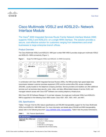
Modifying Beam Profiles with Multimode Fibers By increasing the launch angle of a Gaussian beam into amultimode fiber, the output beam profile can be modified. As the input angle was increased, the proportion of meridionalrays to skew rays increased, first forming a top hat and then adonut beam profile.Initial Profile(Input Angle 0 )Page 1/10Top Hat Profile(Input Angle 11 )Donut Profile(Input Angle 15 )
Background In some applications, an alternative beamdistribution such as a top hat or donut aredesired instead of the inherent Gaussiandistribution provided by typical optics.Pupil For example, diffraction-limited imagingassumes a top-hat distribution in the pupil planethat creates an Airy pattern at the focus (seeFigure 1). In other applications, a Bessel beam is desiredto create an extended depth of focus (seeFigure 2), which can be created by an annulardistribution in the pupil plane or by utilizing anaxicon lens. Most techniques used to modify the beamdistribution lose a significant amount of theinput beam power by either aperturizing smallerregions of the beam to produce the desiredeffect or by using special optical assembliesthat can be expensive.FocusFigure 1: A circular pupil creates Airy pattern atthe focus with a shallow depth of fieldPupilFocusProfile atFocusFigure 2: An annular pupil creates a Bessel beamwith extended depth of field Here, we demonstrate the ability to use a standard multimode fiberpatch cable as a relatively inexpensive method to modify the inputGaussian profile into a top hat and donut profile with minimal loss.Page 2/10Profile atFocus
Theoretical Considerations As the name suggests, multimode fiber supports the propagation of numerous modes down thelength of fiber due to the large core diameter with respect to the input wavelength. To a first approximation, we assume the light that remains bound within the fiber core resultsfrom rays totally internally reflecting at the core/cladding interface along the length of fiber. There are two general types of rays that propagate along the fiber [1]:o Meridional rays pass through the central axis of the fiber after each reflection.o Skew rays never pass through the central axis of the fiber and propagate in a helical pathalong the fiber that is tangent to the inner caustic of the path with radius r. By changing the input angle of the light launched into a multimode fiber, we were able to modifythe proportion of light rays propagating as skew rays vs. meridional rays, and consequently,modify the output from a Gaussian distribution (all meridional rays) to a top hat (mixture ofmeridional and skew rays) to a donut (all skew rays).Meridional RayGaussian DistributionPage 3/10Meridional and Skew RaysSkew RayFlat Top DistributionDonut Distribution[1] Snyder, A. W., & Love, J.D. (1983). Optical Waveguide Theory (pp. 27-31). Chapman & Hall.
Experimental Design Light from a benchtop 675 nm laser diode source was coupled into a single-mode patch cable, collimated with an11 mm focal length lens, and then focused with an identical lens into an 1-meter-long, step-index, multimode fiberwith a Ø200 µm core. The multimode patch cable was wrapped around a Ø1 post 5 times in order to remove cladding modes. A 4X objective lens and 150 mm focal length achromat (tube lens) were used to image the output beam profileonto a CCD camera that was located 5 mm beyond the output tip of the fiber. The input light was set incident at 0 , 11 , and 15 to the input face of the multimode fiber to create the initial, tophat, and donut profiles, respectively. Each time the angle was changed, the alignment of the input fiber was optimized while the output power wasmonitored with a power meter to ensure maximum coupling was achieved. Images were acquired with a 9 second exposure while manually rotating a 1500 grit diffuser placed between thecollimating and focusing lenses to reduce the spatial coherence and create a clean output beam profile.Page 4/10
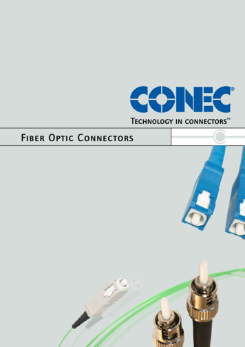
Experiment Setup14651371013Page 5/1011241.2.3.4.5.6.7.8.128Laser Source: S1FC675Input Fiber: P1-630A-FC-2Translation Stages: PT1Rotation Stage: CR1Fiber Collimator: F220FC-B1500 Grit Diffuser: DG10-1500Focusing Lens: C220TMD-B3-Axis Stage: MAX313D99.10.11.12.13.14.Test Fiber: Ø200 µm Core, 0.39 NA: M38L01Microscope Objective: RMS4XNeutral Density Filter: NE30ATube Lens: AC254-150-A1.4 MP Scientific CCD Camera: 1500M-GEPower Sensor Head: S130C withPower Meter: PM100D
Results: Output Profiles Output profiles are shown below for input angles of 0 , 11 , and 15 . The camera imaged the outputbeam profile 5 mm from the output of the fiber. All images were acquired with a spinning diffuser toreduce the spatial coherence and demonstrate the underlying profile from each configuration.o Initial Profile: Baseline profile from a 0 input angle.oTop Hat Profile: As we rotated the input angle, the proportion of light output from the perimeterof the core increased with respect to the light output from the center. We assume this changecorresponds to an increased amount of skew rays with respect to the meridional rays. Outputpower at 11 input angle was 91% of the initial profile.o Donut Profile: Further increasing the input angle increased the proportion of skew rays untilminimal light was observed within the center of the beam profile. Output power at 15 inputangle was 64% of the initial profile. Plots through the center of each profile to support our assumption are provided on the following slide.Initial Profile(Input Angle 0 )Page 6/10Top Hat Profile(Input Angle 11 )Donut Profile(Input Angle 15 )
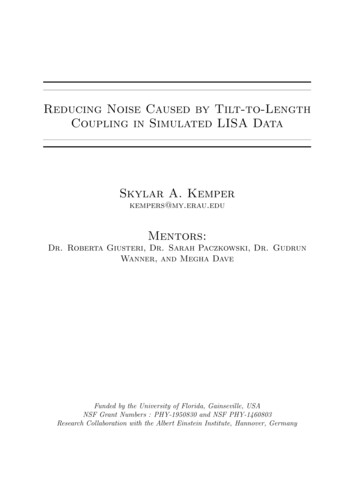
Intensity (a.u.)Initial Profile(Input Angle 0 )Results: Profile FitsProfile1.2 Here we plot the average intensity at eachpoint along the 10 pixel tall line through thecenter of each profile (red) and fit the data(blue) as described below.Fit0.8 Initial Profile fit with a super Gaussian:0.40.002004006008001000Intensity (a.u.)Top Hat Profile(Input Angle 11 )Distance (pixels)Profile1.2𝑦 𝐴𝑒 2(𝑥 𝑥0 )𝑤β,where A 1, x0 519, w 375, and β 4 [1].The departure from a pure Gaussian outputsuggests an initial combination of meridionalrays and skew rays.Fit Top Hat Profile fit with a super Gaussian:0.8𝑦 𝐴𝑒0.4 2(𝑥 𝑥0 )𝑤β,where A 1, x0 519, w 375, and β 16 [1].0.002004006008001000Distance (pixels) Donut Profile internal void fit with a parabola:Intensity (a.u.)Donut Profile(Input Angle 15 )𝑦 𝐴(𝑥 𝑥0 )2 β,Profile1.2where A 10-5, x0 509, and β 0.06 [2].Fit0.8[1] Shealy, D. L., & Hoffnagle, J.A. (2006). Laser beam shaping profiles and propagation.Appl. Optics, 45 (21), 5118-5131. doi:10.1364/AO.45.0051180.4[2] Neupane, B., Chen, F., Sun, W., Chiu, D.T., & Wang, G. (2013). Tuning donut profile forspatial resolution in stimulated emission depletion microscopy. Rev. Sci. Instr. 84 (4),043701. doi:10.1063/1.47996650.00200400600Distance (pixels)Page 7/108001000
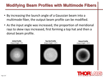
Results: Image at Fiber Face The multimode fiber under test was wrapped five times around a Ø1 post in order to reducethe amount of cladding modes, which is light propagating in the cladding from the initiallaunch or after leaking from the core. Images were also acquired at the fiber face to confirm that the results presented on theprevious slides were not caused by cladding modes. Circles were drawn on the images below to signify the location of the core and cladding. Wecan see that all of the light was output from the core, suggesting that our profiles result fromlight propagating through the core and not the cladding. Note that the beam profiles at the fiber face differ from those obtained at a 5 mm distancefrom the fiber output.Initial Profile(Input Angle 0 )Page 8/10Top Hat Profile(Input Angle 11 )Donut Profile(Input Angle 15 )
Experimental Limitations Only a single multimode core size, fill factor (ratio of input spot size to multimode core),and input numerical aperture and wavelength were shown to demonstrate that theoutput profile from a multimode fiber could be modified. These results are fordemonstration purposes and are far from exhaustive. Input angles were chosen to provide the optimal output profile with minimal power losswith the chosen components. It is important to emphasize that a spinning diffuser was used to reduce the spatialcoherence to demonstrate the overall profile. Without the diffuser, or when the diffuserwas held stationary, a speckle pattern was observed within the overall profile due tothe inference between modes (see below).Output Profile withSpinning DiffuserPage 9/10Output Profile WithoutDiffuser
Summary Here we demonstrated the ability to use a standard multimode fiber patch cable as arelatively inexpensive method to modify an input Gaussian profile into a top hat anddonut profile with minimal loss. Output profiles were imaged 5 mm from the end of the fiber. When the input angle was 0 , the beam profile was a low-order super-Gaussianprofile indicating a high proportion of meridional rays to skew rays. As the input angle increased to 11 , the number of skew rays increased until theoutput beam transformed into a high-order super-Gaussian profile, often called a tophat. As the input angle increased to 15 , the proportion of meridional rays to skew raysincreased until a donut profile was achieved.Page 10/10
Modifying Beam Profiles with Multimode Fibers By increasing the launch angle of a Gaussian beam into a multimode fiber, the output beam profile can be modified. As the input angle was increased, the proportion of meridional rays to skew rays increased, first forming a top hat and then a donut beam profile. Initial Profile (Input Angle 0 )