Transcription
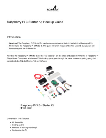
Graphic LCD Hookup Guide a learn.sparkfun.comtutorialAvailable online at: http://sfe.io/t140ContentsIntroductionDisplay OverviewHardware Assembly & HookupExample Code 1: LCD DemoExample Code 2: Drawing BitmapsResources and Going FurtherIntroductionRemember the days when cell phones were still "dumb," and they had physical keypads and just atiny monochrome LCD for a display? Now that iPhones, Galaxies, and the like have revolutionizedthat market, those little LCDs have to find a new purpose in life: adding customized graphicaldisplays to projects!Page 1 of 19
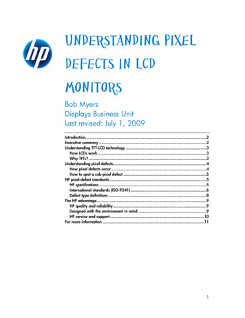
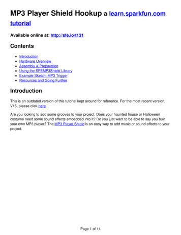
These 84x48 pixel black and white LCDs are what you might have found in an oldNokia 3310.They're not flashy, and they don't have a lot of display real-estate. But, they are easy to control. Ifyou're looking to step up your project's user interface (UI) game from simple displays or LEDs, thisgraphic LCD is a good place to start.Page 2 of 19
Graphic LCD 84x48 - Nokia 5110LCD-10168 8.9518Favorited Favorite 55Wish ListIn this tutorial we'll show how to control these graphic LCDs with just an Arduino and a few wires inbetween. We'll cover everything from hardware assembly to example code, and beyond.Required MaterialsArduino, RedBoard or any Arduino-compatible board.Male headers (included with Retail Kit) to solder to the display and make it breadboardcompatible.Jumper wires to connect from breadboard to Arduino.Breadboard to tie everything together.Suggested ReadingPage 3 of 19
What is an Arduino? -- We'll use an Arduino to send commands and display data to the LCD.Serial Peripheral Interface (SPI) -- An SPI-like interface is used to control the LCD.How to Use a Breadboard -- The breadboard ties the Arduino to the LCD.Display OverviewBefore diving into hookup and example code, let's first take a look at the LCD and its breakoutboard. On this page we'll cover everything from the pinout of the board to the interface used tocontrol the display.The PinoutTo interface with and power the graphic LCD, there are two, parallel 8-pin headers above andbelow it. Flipping the board over, you'll find the labels for each of the pins.As you may be able to tell by the faint traces connecting them, each pin on one header isconnected to the parallel pin on the other side. Here are the eight unique pins along with anoverview of their purpose:PinNumberPin LabelPin FunctionInput/Output?Notes1VCCPositive powersupplyInputSupply range is between 2.7V and3.3VPage 4 of 19
2GNDGroundInput3SCEChip selectInputActive low4RSTResetInputActive low5D/CMode selectInputSelect between command mode (low)and data mode (high).6DN(MOSI)Serial data inInput7SCLKSerial clockInput8LEDLED backlightsupplyInputMaximum voltage supply is 3.3V.Power SuppliesThere are two different supply voltages on the LCD. The most important supply voltage --VCC -supplies the logic circuits inside the LCD. The datasheet states this should be between 2.7 and3.3V. In a normal state, the LCD will consume about 6 or 7mA.The second voltage supply is required for the LED backlights on the board. If you were to removethe LCD from the PCB (not that you should, or need to), you'd see that these are backlights in theirsimplest form -- four white LEDs spaced around the edges of the board. You may also notice thatthere aren't any current limiting resistors.This means you have to be careful with this voltage supply. Either stick a current limiting resistor inseries with the 'LED' pin, or limit the supply to 3.3V max. The LEDs can pull a lot of current! Withnothing to limit them, they'll pull about 100mA at 3.3V.Page 5 of 19
The Control InterfaceBuilt into this LCD is a Philips PCD8544 display controller, which converts the massive parallelinterface of the raw LCD to a more convenient serial one. The PCD8544 is controlled through asynchronous serial interface similar to SPI. There are clock (SCLK) and data (DN) input lines, andan active-low chip select (SCE) input as well.On top of those three serial lines, there is another input --D/C -- which tells the display whether thedata it's receiving is a command or displayable data.For a list of commands, check out the "Instructions" section of the PCD8544 datasheet (page 11).There are instructions to enable clearing of the display, inverting the pixels, powering it down, andmore.Hardware Assembly & HookupBefore we get to uploading code and sending data to the display, let's take care of the hardwarestuff first. That includes assembling the display, and hooking it up to the Arduino.AssemblyTo "assemble" the LCD, you'll need to solder something to one (or both) of the 8-pin headers.There are plenty of options available here. To make the LCD breadboard-compatible, straight orright-angle male headers can be soldered in.Page 6 of 19
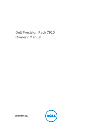
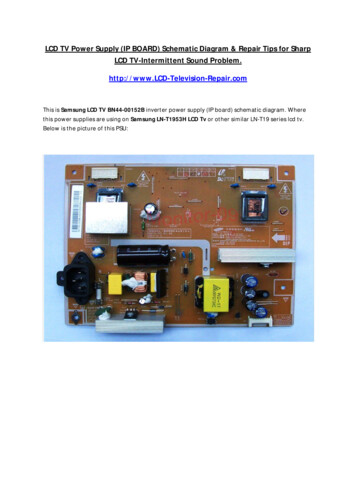
LCD with strait male headers soldered in, plugged into a mini blue breadboard.Otherwise, wires or other connectors can be soldered to the display pins.HookupIn this example we'll be connecting the LCD up to an Arduino, but this hookup should be easilyadaptable to other development platforms. For the data transmission pins -- SCLK and DN(MOSI) -we'll use the Arduino's hardware SPI pins, which will help to achieve a faster data transfer. Thechip select (SCE), reset (RST), and a data/command (D/C) pins can be connected to any digital I/Opin. Finally, the LED pin should be connected to a PWM-capable Arduino pin, so we can dim thebacklight as we please.Unfortunately, the LCD has a maximum input voltage of 3.6V, so we can't hook up a standard 5VArduino straight to it. We need to shift levels. This leads us to a few options for hookup:Direct ConnectThe easiest hookup is to connect the Arduino pins directly to the LCD. To allow for this easyhookup, you'll need a 3.3V-operating Arduino like the 3.3V/8MHz Pro or 3.3V Pro Mini.This setup can work for 5V Arduino's, ignoring the 3.6V limit on the VCC and data lines. We've donethis. It works. But it may decrease your LCD's life.The data pins are connected as follows:LCD PinArduino PinNotes1 - VCC3.3V (VCC)3.3V only (not 5V!)2 - GNDGND3 - SCE7Can be any digital pin.4 - RST6Can be any digital pin.5 - D/C5Can be any digital pin.Page 7 of 19
6DN(MOSI)11Can't be moved.SCLK13Can't be moved.LED9Can be any PWM pin. 330Ω resistor in between thepins.Limiting ResistorsSticking resistors in-line with the data signals is a cheap, and easy way to add some protection tothe 3.3V lines. If you have an Arduino Uno (or similar 5V 'duino) and some 10kΩ and 1kΩ resistorslying around, try this:The pins are connected the same as in the above example, however each signal has an inlineresistor. There are 10kΩ resistors between the SCLK, DN, D/C, and RST pins. A1kΩ resistorbetween SCE and pin 7. And the 330Ω resistor remains between pin 9 and the LED pin.Level ConvertersFinally, a third option for hookup is to use actual level converters to switch between 5V and 3.3V.Boards like the Bi-Directional Logic Level Converter and the TXB0104 are perfect for something likethis.Page 8 of 19
Unfortunately, the LCD has five 3.3V signal inputs and the level shifters only have four channels. Ifyou want to keep the circuit to a single shifter, you can permanently tie RST high (through a 10kΩresistors), and run the other signals through the shifter. You lose remote reset capability, but therest of the control remains.Check out the hook up guides for those boards for more help in shifting the signal between Arduinoand LCD.Example Code 1: LCD DemoWith the hardware all hooked up, we're ready to upload a sketch and start drawing on the LCD!The SketchNote: This example assumes you are using the latest version of the Arduino IDE on your desktop.If this is your first time using Arduino, please review our tutorial on installing the Arduino IDE.Download, unzip, open the sketch from the GitHub repository.Nokia 5100 LCD Example Example Sketch (ZIP)Below is a snippet of the example LCD control code. This small novella of a sketch shows off anarray of graphics driver functions, character drawing tools, and other useful functions to help youget started using the LCD. You will need to include the LCD Functions.h header in the samedirectory as the sketch folder from the download. Otherwise, your code will not compile whenuploading to Arduino.language:c/* Nokia 5100 LCD Example CodeGraphics driver and PCD8544 interface code for SparkFun's84x48 Graphic LCD.Page 9 of 19
https://www.sparkfun.com/products/10168by: Jim Lindblomadapted from code by Nathan Seidle and mish-mashed withcode from the ColorLCDShield.date: October 10, 2013license: Officially, the MIT License. Review the included License.md fileUnofficially, Beerware. Feel free to use, reuse, and modify thiscode as you see fit. If you find it useful, and we meet someday,you can buy me a beer.This all-inclusive sketch will show off a series of graphicsfunctions, like drawing lines, circles, squares, and text. Thenit'll go into serial monitor echo mode, where you can typetext into the serial monitor, and it'll be displayed on theLCD.This stuff could all be put into a library, but we wanted toleave it all in one sketch to keep it as transparent as possible.Hardware: (Note most of these pins can be swapped)Graphic LCD Pin ---------- Arduino Pin1-VCC---------------- 5V2-GND---------------- GND3-SCE---------------- 74-RST---------------- 65-D/C---------------- 56-DN(MOSI) ---------------- 117-SCLK---------------- 138-LED- 330 Ohm res -- 9The SCLK, DN(MOSI), must remain where they are, but the otherpins can be swapped. The LED pin should remain a PWM-capablepin. Don't forget to stick a current-limiting resistor in linebetween the LCD's LED pin and Arduino pin 9!*/#include SPI.h #include "LCD Functions.h"/* This array is the same size as the displayMap. We'll use itas an example of how to draw a bitmap. xkcd comic transposingmakes for an excellent display application.For reference, see: http://xkcd.com/149/ */static const char xkcdSandwich[504] PROGMEM {0xFF, 0x8D, 0x9F, 0x13, 0x13, 0xF3, 0x01, 0x01, 0xF9, 0xF9, 0x01, 0x81, 0xF9, 0xF9, 0x01, 0xF1,0xF9, 0x09, 0x09, 0xFF, 0xFF, 0xF1, 0xF9, 0x09, 0x09, 0xF9, 0xF1, 0x01, 0x01, 0x01, 0x01, 0x01,0xF9, 0xF9, 0x09, 0xF9, 0x09, 0xF9, 0xF1, 0x01, 0xC1, 0xE9, 0x29, 0x29, 0xF9, 0xF1, 0x01, 0xFF,0xFF, 0x71, 0xD9, 0x01, 0x01, 0xF1, 0xF9, 0x29, 0x29, 0xB9, 0xB1, 0x01, 0x01, 0x01, 0xF1, 0xF1,0x11, 0xF1, 0xF1, 0xF1, 0xE1, 0x01, 0xE1, 0xF1, 0x51, 0x51, 0x71, 0x61, 0x01, 0x01, 0xC1, 0xF1,0x31, 0x31, 0xF1, 0xFF, 0xFF, 0x00, 0x01, 0x01, 0x01, 0x01, 0x60, 0xE0, 0xA0, 0x01, 0x01, 0x81,0xE1, 0x61, 0x60, 0xC0, 0x01, 0xE1, 0xE1, 0x21, 0x21, 0xE0, 0xC1, 0x01, 0xC1, 0xE1, 0x20, 0x20,0xFC, 0xFC, 0xE0, 0xE0, 0xC1, 0xE1, 0xE0, 0xC1, 0xE0, 0xE1, 0x01, 0xFC, 0xFC, 0x21, 0x21, 0xE1,0xC1, 0xE5, 0xE4, 0x01, 0xC1, 0xE0, 0x20, 0x21, 0x20, 0x00, 0x01, 0xFD, 0xFD, 0x21, 0x20, 0xE0,0x00, 0x00, 0x01, 0x01, 0xC0, 0x61, 0x31, 0x31, 0x21, 0x20, 0xC0, 0x81, 0x01, 0x01, 0x01, 0x00,0x00, 0x00, 0x00, 0x01, 0x01, 0x01, 0x01, 0xFF, 0xFF, 0x00, 0x00, 0x00, 0x00, 0x01, 0x03, 0x02,0x03, 0x01, 0x00, 0x01, 0x03, 0xF2, 0x1A, 0x0B, 0x08, 0x0B, 0x1B, 0x10, 0x60, 0xE3, 0x03, 0x00,0x01, 0x03, 0x02, 0x02, 0x03, 0x03, 0x00, 0x03, 0x03, 0x00, 0x00, 0x03, 0x03, 0x00, 0x00, 0x03,Page 10 of 19
0x03, 0x00, 0x00, 0x03, 0x03, 0x03, 0x03, 0x00, 0x01, 0x03, 0x02, 0x02, 0x03, 0x01, 0x00, 0x03,0x03, 0x00, 0x00, 0x03, 0x00, 0x00, 0x00, 0x3E, 0x63, 0x80, 0x80, 0x80, 0x80, 0x60, 0x3F, 0x07,0x00, 0x00, 0x00, 0x00, 0x00, 0x00, 0x00, 0x00, 0x00, 0x00, 0x00, 0xFF, 0xFF, 0x00, 0x00, 0x00,0x00, 0x00, 0x00, 0x00, 0xFE, 0x01, 0x01, 0x01, 0x02, 0x03, 0x3E, 0xE8, 0xF8, 0xF0, 0xD0, 0x90,0x18, 0x0F, 0x00, 0x00, 0x00, 0x00, 0x00, 0x00, 0x00, 0x00, 0x00, 0x00, 0x00, 0x00, 0x00, 0x00,0x00, 0x00, 0x00, 0x00, 0x00, 0x00, 0x00, 0x00, 0x00, 0x00, 0x00, 0x00, 0x00, 0x00, 0x00, 0x00,0x00, 0x00, 0x00, 0x00, 0x00, 0x00, 0x00, 0x00, 0x00, 0x00, 0x00, 0x00, 0x00, 0xC0, 0x38, 0xFF,0x0C, 0x38, 0xE0, 0x80, 0x00, 0x00, 0x00, 0x00, 0x00, 0x00, 0x00, 0x00, 0x00, 0x00, 0x00, 0xFF,0xFF, 0x00, 0x00, 0x00, 0x00, 0x00, 0x00, 0x00, 0x1F, 0xF0, 0x00, 0x00, 0x00, 0x00, 0x00, 0x33,0x5F, 0x8F, 0x84, 0x05, 0x07, 0x06, 0x0C, 0x0E, 0x0E, 0x0C, 0x14, 0x34, 0x68, 0x88, 0xD8, 0x70,0x00, 0x00, 0x00, 0x00, 0x00, 0xE0, 0x10, 0x10, 0x10, 0xF0, 0xE0, 0x00, 0xF0, 0xF0, 0x00, 0x80,0x80, 0x00, 0x00, 0x80, 0x80, 0x80, 0x80, 0x00, 0x80, 0x80, 0x00, 0x80, 0x00, 0x00, 0x20, 0x38,0x0E, 0x01, 0xC0, 0x3F, 0xE0, 0x00, 0x00, 0x03, 0x0E, 0x08, 0x00, 0x00, 0x00, 0x00, 0x00, 0x00,0x00, 0x00, 0x00, 0xFF, 0xFF, 0x80, 0x80, 0x80, 0x80, 0x80, 0x80, 0x80, 0xB6, 0xED, 0xC0, 0xC0,0xC0, 0xE0, 0xA0, 0xA0, 0xA0, 0xA0, 0xA1, 0xA1, 0xA1, 0xA1, 0xA1, 0xA1, 0xA1, 0xE1, 0xE1, 0xC1,0xEF, 0xBB, 0x83, 0x86, 0x88, 0xB0, 0x80, 0x80, 0x80, 0x8F, 0x90, 0x90, 0x90, 0x9F, 0x8F, 0x80,0x9F, 0x9F, 0x87, 0x8D, 0x98, 0x80, 0x8C, 0x9E, 0x92, 0x92, 0x9F, 0xC0, 0xC7, 0xFF, 0xB8, 0x8F,0x80, 0x90, 0x90, 0xC0, 0xF0, 0x8E, 0x81, 0x80, 0x81, 0x8F, 0xB8, 0xE0, 0x80, 0x80, 0x80, 0x80,0x80, 0x80, 0x80, 0x80, 0x80, 0x80, 0x80, 0xFF,};void setup(){Serial.begin(9600);lcdBegin(); // This will setup our pins, and initialize the LCDupdateDisplay(); // with displayMap untouched, SFE logosetContrast(40); // Good values range from 40-60delay(2000);lcdFunTime(); // Runs a 30-second demo of graphics functions// Wait for serial to come in, then clear display and go to echowhile splay();}// Loop turns the display into a local serial monitor echo.// Type to the Arduino from the serial monitor, and it'll echo// what you type on the display. Type to clear the display.void loop(){static int cursorX 0;static int cursorY 0;if (Serial.available()){char c Serial.read();switch (c){case '\n': // New linecursorY 8;break;Page 11 of 19
case '\r': // Return feedcursorX 0;break;case ' ': // Use to clear the screen.clearDisplay(WHITE);updateDisplay();cursorX 0; // reset the cursorcursorY 0;break;default:setChar(c, cursorX, cursorY, BLACK);updateDisplay();cursorX 6; // Increment cursorbreak;}// Manage cursorif (cursorX (LCD WIDTH - 4)){ // If the next char will be off screen.cursorX 0; // . reset x to 0.cursorY 8; // .and increment to next line.if (cursorY (LCD HEIGHT - 7)){ // If the next line takes us off screen.cursorY 0; // .go back to the top.}}}}/* This function serves as a fun demo of the graphics driverfunctions below. */void lcdFunTime(){clearDisplay(WHITE); // Begin by clearing the displayrandomSeed(analogRead(A0));/* setPixel Example */const int pixelCount 100;for (int i 0; i pixelCount; i ){// setPixel takes 2 to 3 parameters. The first two params// are x and y variables. The third optional variable is// a "color" boolean. 1 for black, 0 for white.// setPixel() with two variables will set the pixel with// the color set to black.// clearPixel() will call setPixel with with color set to// white.setPixel(random(0, LCD WIDTH), random(0, LCD HEIGHT));// After drawing something, we must call updateDisplay()// to actually make the display draw something new.updateDisplay();delay(10);}setStr("full of stars", 0, LCD HEIGHT-8, BLACK);updateDisplay();delay(1000);// Seizure time!!! Err.demoing invertDisplay()Page 12 of 19
for (int i 0; i 5; i ){invertDisplay(); // This will swap all bits in our displaydelay(200);invertDisplay(); // This will get us back to where we starteddelay(200);}delay(2000);/* setLine Example */clearDisplay(WHITE); // Start freshint x0 LCD WIDTH/2;int y0 LCD HEIGHT/2;for (float i 0; i 2*PI; i PI/8){// Time to whip out some maths:const int lineLength 24;int x1 x0 lineLength * sin(i);int y1 y0 lineLength * cos(i);// setLine(x0, y0, x1, y1, bw) takes five variables. The// first four are coordinates for the start and end of the// line. The last variable is the color (1 black, 0 white).setLine(x0, y0, x1, y1, BLACK);updateDisplay();delay(100);}// Demo some backlight tuningfor (int j 0; j 2; j ){for (int i 255; i 0; i- 5){analogWrite(blPin, i); // blPin is ocnnected to BL LEDdelay(20);}for (int i 0; i 256; i 5){analogWrite(blPin, i);delay(20);}}/* setRect Example */clearDisplay(WHITE); // Start fresh// setRect takes six parameters (x0, y0, x1, y0, fill, bw)// x0, y0, x1, and y0 are the two diagonal corner coordinates// fill is a boolean, which determines if the rectangle is// filled in. bw determines the color 0 white, 1 black.for (int x 0; x LCD WIDTH; x 8){ // Swipe right blacksetRect(0, 0, x, LCD HEIGHT, 1, BLACK);updateDisplay();delay(10);}for (int x 0; x LCD WIDTH; x 8)Page 13 of 19
{ // Swipe right whitesetRect(0, 0, x, LCD HEIGHT, 1, WHITE);updateDisplay();delay(10);}for (int x 0; x 12; x ){ // Shutter swipesetRect(0, 0, x, LCD HEIGHT, 1, 1);setRect(11, 0, x 12, LCD HEIGHT, 1, BLACK);setRect(23, 0, x 24, LCD HEIGHT, 1, BLACK);setRect(35, 0, x 36, LCD HEIGHT, 1, BLACK);setRect(47, 0, x 48, LCD HEIGHT, 1, BLACK);setRect(59, 0, x 60, LCD HEIGHT, 1, BLACK);setRect(71, 0, x 72, LCD HEIGHT, 1, BLACK);updateDisplay();delay(10);}// 3 Dee!setRect(25, 10, 45, 30, 0, WHITE);setRect(35, 20, 55, 40, 0, WHITE);setLine(25, 10, 35, 20, WHITE);setLine(45, 30, 55, 40, WHITE);setLine(25, 30, 35, 40, WHITE);setLine(45, 10, 55, 20, WHITE);updateDisplay();delay(2000);/* setCircle Example */clearDisplay(WHITE);// setCircle takes 5 parameters -- x0, y0, radius, bw, and// lineThickness. x0 and y0 are the center coords of the circ.// radius is the.radius. bw is the color (0 white, 1 black)// lineThickness is the line width of the circle, 1 smallest// thickness moves in towards center.for (int i 0; i 20; i ){int x random(0, LCD WIDTH);int y random(0, LCD HEIGHT);setCircle(x, y, i, BLACK, 1);updateDisplay();delay(100);}delay(2000);/* setChar & setStr Example */// setStr takes 4 parameters: an array of characters to print,// x and y coordinates for the top-left corner. And a colorsetStr("Modern Art", 0, 10, WHITE);updateDisplay();delay(2000);/* setBitmap Example */// setBitmap takes one parameter, an array of the same size// as our screen.setBitmap(xkcdSandwich);Page 14 of 19
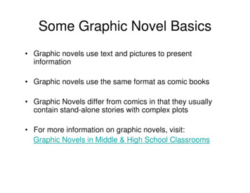
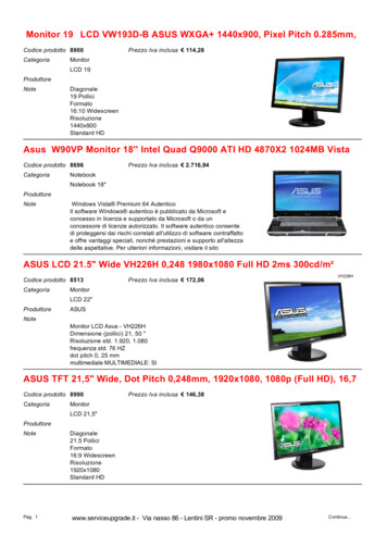
updateDisplay();}For help understanding the sketch, check the comments in the code. Most of the action takes placein the lcdFunTime() function.Heads up! If the display is not showing pixels even with the correct logic levels and example code,it may just have slight variances in the way that they were manufactured. You can see the pixelsfaintly on the screen at an angle or pushing down on the LCD. You will need to try and set thecontrast where it says setContrast(40) on line 87 to a value of 60. There is probably some variances inthe LCD’s contrast which might explain why certain LCDs have issues displaying defined pixels onthe screen.The Sketch in ActionOnce uploaded to your Arduino, the sketch will begin by running the demo -- a set of basicanimations and graphics functions. To begin, we'll draw some random pixels on the screen ("It's fullof stars."). Then we'll move on to examples of drawing lines, rectangles, and circles. Throughoutthere are examples of drawing characters and strings. Finally the demo closes out with anhomage to a monochrome comic which seems a perfect fit for this little monochrome LCD.Page 15 of 19
This is a demo of drawing bitmaps on the screen, which is one of the more rewarding tasks we canaccomplish with the 'duino/LCD combo.After the demo runs its course, the sketch will enter into a serial echo mode. Open the serialmonitor (set the baud rate to 9600 bps), and type stuff over to the Arduino. It should start printingeverything you send it onto the LCD.If you're intrigued by the possibilities of drawing bitmaps on the screen, check out the next page!We'll show you how to import your own 84x48 bitmap and draw it on the screen.Example Code 2: Drawing BitmapsIf the last demo has you chomping at the bit to design your own 84x48 bitmaps and display them,continue reading through this example. We'll show you how to scale and import a bitmap, thencompile it into your Arduino code and send it to the LCD, so you can have your own, sillly graphic.Page 16 of 19
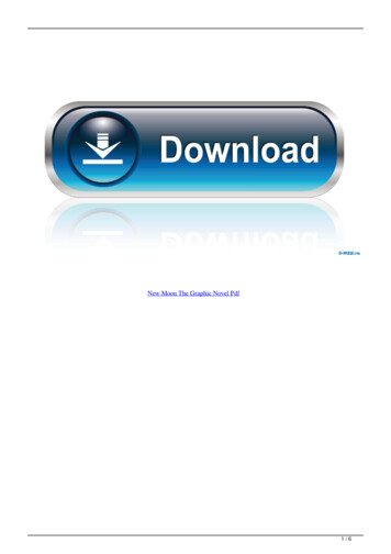
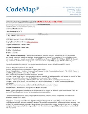
Find/Make/Modify a BitmapTo begin, find a bitmap image that you'd like to print to the LCD. 84x48 monochrome pixels doesn'tgive you a lot of room, but you can still get some fun stuff on there. Here are a few examples:After you've picked an image, you'll need to massage it to make it bothmonochrome (2-bit color)and 84 x 48 pixels. Most standard image editors can help with this. For Windows users,Paint is allyou need to scale the image. Then save it as a monochrome bitmap.Convert Bitmap to ArrayThe next step is converting that regular image file to a 504-byte array ofchar's. There are a numberof programs that can help with this around the web. We recommend LCD Assistant.To load up an image in LCD Assistant, go toFile Load Image. A preview of the image shouldopen up, make sure it's the right size -- 84 pixels wide, 48 pixels tall. Also make sure the Byteorientation is set to Vertical and the Size endianness is set to Little. The rest of the default settings(8 pixels/byte, etc.) should already be set correctly:Page 17 of 19
Then go to File Save output to generate a temporary text file. Open that text file to have a look atyour shiny new array. You'll need to modify the type of the array to be just achar (no unsigned orconst). Also make sure the array has the proper naming conventions (no dashes, don't start with anumber, etc.).Import into the Sketch and Draw!With that array created, copy the entire table over to your Arduino sketch. Use the same sketchfrom Example 1. Paste the array wherever you'd like. Now, to test out your drawing, replace thesetup() and loop() in the last sketch with the below (making sure the rest of the functions and variablesremain in the sketch):language:c// .LCD definitions, variables, and bitmap array defined above.void setup(){lcdBegin(); // This will setup our pins, and initialize the LCDsetContrast(60); // Good values range from 40-60setBitmap(flameBitmap); // flameBitmap should be replaced with the name of your BMP arrayupdateDisplay(); // Update the display to make the array show up.}void loop(){}Page 18 of 19
// LCD control and graphics functions defined below.Fun stuff! Now you can overlay text, or draw on on your bitmap. You can even try importing multiplegraphics to create animations!Resources and Going FurtherThanks for checking out our Monochrome 84 x 48 Graphic LCD Hookup Guide! Should you requireany further resources to get your LCD up and running, here are some handy places to look:LCD and Driver ResourcesPCD8544 LCD Controller DatasheetLCD Datasheet -- Not exactly SparkFun's LCD, but a pretty close match.GitHub Repository - Example code used in this tutorial for the Nokia graphic LCD.Arduino Libraries and CodePCD8544 Arduino Library -- A dependable Arduino library for the PCD8544 LCD driver.AdaFruit LCD Library -- Adafruit has an amazing Arduino library to help interface withthis LCD. Also requires their graphics library.Bitmap ToolsLCD AssitantBitmap2LCDTheDotFactory -- Nifty tool to create array definitions for custom fonts.Going FurtherNow that you've got control of your graphic LCD, you can embed it into all sorts of cool projects. Ifyou need some inspiration, here are some related tutorials to help you out:OLED Display Hookup Guide -- While not exactly an LCD, this OLED provides a nice, crisptext display to your project.MP3 Player Shield Music Box -- This MP3 Player Music Box could be well served by a sweetgraphic display. Hmm.ITG-3200 Hookup Guide -- The ITG-3200 is a fully-featured 3-axis gyroscope sensor. Thisdisplay could be used to create a visual angular velocity meter.learn.sparkfun.com CC BY-SA 3.0 SparkFun Electronics Niwot, ColoradoPage 19 of 19
directory as the sketch folder from the download. Otherwise, your code will not compile when uploading to Arduino. language:c /* Nokia 5100 LCD Example Code Graphics driver and PCD8544 interface code for SparkFun's 84x48 Graphic LCD. Page 9 of 19