Transcription
This article has been accepted for publication in a future issue of this journal, but has not been fully edited. Content may change prior to final publication. Citation information: DOI 10.1109/TSTE.2019.2890828, IEEETransactions on Sustainable Energy1Grid-Connected Wind-PhotovoltaicCogeneration Using Back-to-BackVoltage Source ConvertersAmr Ahmed A. Radwan, Member, IEEE and Yasser Abdel-Rady I. Mohamed, Senior Member, IEEEAbstract—This paper introduces a new topology, yet simple andefficient, for a grid-connected wind-photovoltaic (PV) cogenerationsystem. A permanent magnet synchronous generator-based fullscale wind turbine is interfaced to the utility-grid via back-to-back(BtB) voltage-source converters (VSCs). A PV solar generator isdirectly connected to the dc-link capacitor of the BtB VSCs. Nodc/dc conversion stages are required, and hence the systemefficiency is maximized. The proposed topology features anindependent maximum power point tracking for both the wind andthe PV generators to maximize the extraction of the renewableenergy. The regulation of the VSCs is achieved via the vectorcontrol scheme in the rotating reference frame. The detailed smallsignal models for the system components are developed toinvestigate the overall stability. The influence of the utility-gridfaults on the performance of the proposed system is also evaluated.Nonlinear time-domain simulation results under differentoperating conditions are presented to validate the effectiveness ofthe proposed topology.Index Terms--AC-DC power converters, DC-AC powerconverters, maximum power point trackers, permanent magnetmachines, solar power generation, wind power generation.I. INTRODUCTIONThe cost of the wind and solar energy generation has beenrapidly falling since the last decade. Driven by their economicand technical incentives, the global installed capacity ofphotovoltaic (PV) and wind generators has approached 303Gigawatt (GW) and 487 GW in 2016, as compared to 6 GW and74 GW in 2006, respectively [1].Due to the intermittent and unregulated nature of the windand solar energy, power-electronic converters are utilized as aninterfacing stage to the load-side or the utility-grid, and hencedistributed generation units are created [2]-[3]. In literature,most of the distributed generation systems are solely dedicatedfor one form of renewable resources, e.g., a solar energy as in[4]-[5] or a wind energy as in [6]-[8].In order to maximize the benefits of the available renewableresources, the combination of the wind and solar energy in thesame vicinity has been considered [9]-[22]. The cogeneration ofthe wind and solar energy has the following characteristics; 1)the availability of the wind and solar energy is generallycomplementary, and hence combining both forms of energyincreases the overall operational efficiency [23]. 2) thecombination of the wind and solar co-generators optimizes theA. Radwan is with the Engineering and Design Department, (email:amr.radwan@ieee.org).Y. Mohamed is with the Department of Electrical and ComputerEngineering, University of Alberta, Edmonton, AB T6G2V4, Canada (email:yasser2@ualberta.ca).utilization of lands resources, and hence improves the capitalinvestments [24]. 3) as compared to the static PV generators, thewind-solar cogeneration systems are more dynamically capableto support the utility-grid due to the available moment of inertiain the mechanical system of the wind generators [8]. 4) havingtwo sources of energy increases the generation reliability [9][10].The grid-connected wind-PV cogeneration systems are notwidely addressed [9]-[15]. On the contrary, several wind-PVcogeneration systems are proposed for the standalone off-gridapplications [10], [16]-[22].A standalone wind-PV cogeneration system is proposed in[16]-[17]. On the small-scale level, a single-phase cogenerationsystem has been proposed in [18] whereas a laboratory-scalesystem is introduced in [19]-[20]. Generally, the systemstructure in [16]-[20] comprises a common dc-bus that interfacesseveral parallel connected converters-interfaced renewableenergy resources, which might reduce the overall systemefficiency and increase the cost [12]. More importantly, thecascaded connection of power converters requires rigorouscontrollers coordination to avoid the induced interactionsdynamics, which might yield instabilities [25]-[26]. A back-toback (BtB) voltage-source converter (VSC) connected to adoubly-fed induction generator is used to interface a dc-dcconverter-interfaced PV generator and an energy storage unit in[21]. In [22], a PV generator charging a battery bank andinterfaced to a wind driven induction generator via a VSC isproposed. The wind-PV cogeneration systems in [21]-[22]highlights the efficient integration of the renewable energyresources with the minimal utilization of power-electronicconversion stages. However, these systems are proposed forspecific off-grid applications.In [12]-[14], the utility-grid integration of the renewableenergy resources has been improved by using multiple-inputconverters. A buck/buck-boost fused dc-dc converter isproposed in [12]. A dc-dc converter with a current-sourceinterface, and a coupled transformer is proposed in [13] and[14], respectively. However, the proposed systems in [12]-[14]are based on the dc power distribution which might not be theideal distribution medium in the ac-dominated power systems.Up to the authors’ best knowledge, the combination of thegrid-connected wind-PV systems has been solely addressed in[15]. The system in [15] comprises a BtB VSCs to interface thePV and wind generators to the utility-grid. On the machine-sideVSC, the dc-link voltage is regulated to the maximum powerpoint tracking (MPPT) value of the PV panels by an outer loopproportional-and-integral (PI) dc voltage controller. Thereference values of the machine-side currents are calculatedusing the synchronous detection method, and a hysteresis currentcontroller is utilized for the regulation. On the grid-side-VSC, a1949-3029 (c) 2018 IEEE. Personal use is permitted, but republication/redistribution requires IEEE permission. See http://www.ieee.org/publications standards/publications/rights/index.html for more information.
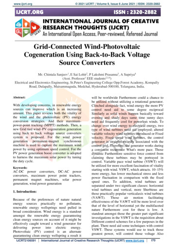
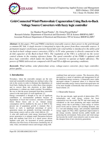
This article has been accepted for publication in a future issue of this journal, but has not been fully edited. Content may change prior to final publication. Citation information: DOI 10.1109/TSTE.2019.2890828, IEEETransactions on Sustainable Energy2hysteresis grid-current controller is used to inject the totalcurrents into the utility-grid. In spite of the potential benefits ofthe proposed system in [15], the following challenges are noted;1) the MPPT of either the PV and wind power involves theoperation of both VSCs, which in some cases might decreasesthe system reliability and increases the losses. For instance, ifthe wind velocity is lower than the cut-off speed of the windturbine, i.e., no wind power, the machine-side VSC may beunable to track the solar PV MPPT dc-link voltage [15]. 2) thecurrents of the machine and grid-side converters are regulatedusing hysteresis controllers resulting in a variable switchingfrequency and higher harmonic contents.Motivated by the promising benefits of the wind-PVgeneration systems, this paper introduces a new topology, yetsimple and efficient to interface both the wind and PVgenerators into the utility-grid. The contributions of this paperare as following;1) The realization of the grid-connected wind-PV cogenerationsystem using BtB VSCs with no extra dc/dc conversionstages.2) Independent MPPT operation where the MPPT of the windand PV generators is solely achieved by the voltage-sourcerectifier (VSR), and the voltage-source inverter (VSI),respectively.3) The development of the complete small-signal state-spacemodel of the wind-PV cogeneration system to characterizethe overall system stability.4) The performance of proposed system has been investigatedunder different operating conditions, including the utilitygrid faults, using time-domain simulations.II. MODELING AND CONTROL OF THE PROPOSED WINDPHOTOVOLTAIC COGENERATION SYSTEMAs shown in Fig. 1, the proposed system consists of a VSR tointerface the wind generator, and a VSI to connect thecogeneration system into the utility-grid. The PV generator isdirectly connected to the dc-link capacitor of the BtB VSCs via adc cable [27]. The VSR and VSI are two-level convertersconsisting of six cells; each comprises an insulated-gate-bipolartransistor (IGBT) in parallel with a diode.In the following subsections, the complete modeling andcontrol of the proposed system is provided.A. Wind GeneratorA full-scale wind turbine (FSWT) utilizing a permanentmagnet synchronous generator (PMSG) is selected for its lowmaintenance and low operational cost [2]. The wind turbinemodel is represented as following, 5𝑃" % 𝐶' (ϐ, 𝜆)𝜌𝜋𝑅% 𝑣1234,678𝜆 9:; (1)where 𝑃" is the mechanical power captured by the wind turbineblades; 𝐶' is the rotor coefficient which is a non-linear functionof the blade pitch angle (ϐ) and the tip-speed ratio (𝜆); 𝜌 is theair density; 𝑅 is the radius of the wind turbine blade; 𝑣1234 is thewind speed; and 𝜔? is the mechanical speed of the rotor. In thispaper, ϐ is set to zero in the normal operating conditions tomaximize the wind power generation [13]. The PMSG ismodeled as following,𝑣̅A 𝑅A 𝚤̅A 𝐿A454E̅F4G 𝑗Ƥ𝜔? (𝜓 𝐿A 𝚤̅A )(2)𝐽 4G 𝜔? 𝛽𝜔? % Ƥ𝜓𝐼AN 𝑇"(3)In (2), 𝑣̅A and 𝚤̅A are the stator voltage and current in the complexvectors representation, respectively, where a complex vector𝑥̅ 𝑋4 𝑗𝑋N such that 𝑋4 and 𝑋N are the direct (𝑑 ) andquadrature (𝑞 ) components of 𝑥̅ in the rotating referenceframe; 𝑅A and 𝐿A are the stator-winding resistance andinductance, respectively; 𝑗 is the imaginary unit number; 𝜓 isthe flux linkage of the rotor magnets; Ƥ is the number of polespairs; 𝑇" is the mechanical torque; whereas 𝐽 and 𝛽 are themotor inertia, and viscous friction, respectively.B. Machine-Side Voltage Source Rectifier (VSR)Fig. 2 shows the relationship between the mechanical rotorspeed and the generated wind-turbine power at different windspeeds. At any wind speed, there is an optimal value of themechanical rotor speed that corresponds to the generation of themaximum wind power. The extraction of the maximum windpower is achieved by the VSR in Fig. 1. The MPPT algorithmfor the wind generator (MPPT1 ) uses the wind speed (𝑣1 ) togenerate the optimal value of the rotor speed (𝜔? ) following themechanical characteristics in Fig. 2 [17], [19].As shown in (4), a PI speed controller (𝐺A (𝑠) 𝑔'A 𝑔2A 𝑠)is implemented to regulate the rotor speed (𝜔? ) to the optimalvalue (𝜔? ) and dictates the 𝑞-component of stator current ), whereas the 𝑑-component of stator currentreference (𝐼AN reference (𝐼A4 ) is set to zero to operate at the maximum producedtorque [19]. 𝐼AN (𝜔? 𝜔? )𝐺A (𝑠), 𝐼A4 0(4)where 𝑠 represents the differential operator. within the bandwidthSolving (3) and (4), assuming 𝐼AN 𝐼ANof the speed controller (𝐺A (𝑠)), and setting 𝑔2A 𝑔'A 𝛽 𝐽, theclosed-loop transfer-function of the speed controller becomes;55𝜔? 𝜔? Ƥ𝜓𝑔'A 𝐽a b𝑠 Ƥ𝜓𝑔'A 𝐽ac,%%wherethe5bandwidth is Ƥ𝜓𝑔'A 𝐽 [rad/s], and is selected to be around%10% of the bandwidth of the inner current controller [discussedin the following paragraph]. The speed controller parameters,i.e., 𝑔'A and 𝑔2A , can be tuned accordingly.As shown in Fig. 1 and (5), a PI current controller (𝐺2 (𝑠) 𝑔'2 𝑔22 𝑠) is employed so that the generated stator currents ofthe PMSG follow the corresponding references in (4).𝑣̅A (𝚤̅A 𝚤̅A )𝐺2 (𝑠) 𝑗Ƥ𝜔? 𝐿A 𝚤̅A 𝑗Ƥ𝜓𝐻𝜔?(5)where 𝑗Ƥ𝜔? 𝐿A 𝚤̅A are the decoupling loops; 𝐻 is a gain; whereasthe superscript “ ” denote the steady-state value of the variable.The current controller in (5) is designed by solving (2) and (5).By setting 𝑔22 𝑔'2 𝑅A 𝐿A , the closed loop transfer function of the current controller becomes; 𝐼A4 𝐼A4 1 (𝜏2 𝑠 1), wherethe bandwidth of the current controller is 1 𝜏2 𝑔'2 𝐿A [rad/s],and is selected to be around 10-20% of the switching frequencyof the VSR.1949-3029 (c) 2018 IEEE. Personal use is permitted, but republication/redistribution requires IEEE permission. See http://www.ieee.org/publications standards/publications/rights/index.html for more information.
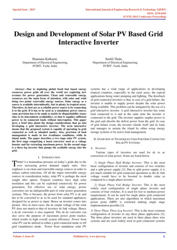
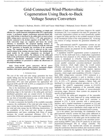
This article has been accepted for publication in a future issue of this journal, but has not been fully edited. Content may change prior to final publication. Citation information: DOI 10.1109/TSTE.2019.2890828, IEEETransactions on Sustainable Energy3Solar GeneratorVpvVSRWind GeneratorPMSGis vsCdcMPPTwd/dtω*rωrSpeedControlVSIis*CfSPWMPWMAC CurrentControlvgvc ic Lf Rf vf ig Lg Rg-θrvw IpvRdcLdcVdcAC CurrentControli*cDC VoltageControlVdc*MPPTsFig. 1. The proposed wind-PV cogeneration system.Fig. 2. Mechanical characteristics of the wind turbine at different wind speeds.C. Photovoltaic GeneratorIn this paper, a PV array of a model “PV-UD190MF5” hasbeen considered [28]. The PV model is highly-nonlinear butreflects no dynamic performance on the transient stability of thesystem. The model of the PV generator is given in Appendix Awhereas the dc cable dynamics in Fig. 1 are modeled asfollowing;𝑉'9 𝑉4j 𝑅4j 𝐼'9 𝐿4j4klm4G(6)The 𝐼'9 -𝑉'9 characteristics of the PV array are shown in Fig.3. At any solar irradiance level, there is an optimal operating , 𝑉'9) corresponding to the maximum generated PVpoint (𝐼'9power. As shown in Fig. 1, the MPPT algorithm of the PV array(MPPTA ) uses the solar irradiance level (𝑆) to determine the ) [from Fig. 3] thatoptimal value of the dc-link voltage (𝑉4jcorresponds to the generation of the maximum PV power [4].Referring to Fig. 1, the nominal voltage for PV arrays isdesigned at 1457V. With nowadays improvements in thecentralized power converters, PV arrays can be directlyconnected to a dc-link with nominal dc voltage up to 1500V at2.0 MVA [29].D. Grid-Side Voltage Source Inverter (VSI)As shown in Fig. 1, the ac-side of the VSI is terminated byan inductive filter (𝐿o ) with an internal resistance (𝑅o ) and ashunt capacitor (𝐶o ). The root-mean-square (rms) value of thethree-phase terminal voltage and currents of the VSI are 𝑣j and𝑖j , respectively. The utility-grid-impedance comprises aninductive part (𝐿t ) in series with the equivalent resistance of theline (𝑅t ); 𝑣t and 𝑖t are the utility-grid three-phase 𝑟𝑚𝑠 voltageand currents, respectively.Fig. 3. 𝐼'9 𝑉'9 characteristics of the PV array at different solar irradiancelevels.The 𝐿o -𝐶o filter and the utility-grid impedance are modelledas following;𝑣̅j 𝑣̅o 𝑅o 𝚤̅j 𝐿o4E̅w𝑣̅o 𝑣̅t 𝑅t 𝚤̅t 𝐿t𝚤̅j 𝐶o49yz4G 𝑗𝜔𝐿o 𝚤̅j4G4E̅x4G 𝑗𝜔𝐿t 𝚤̅t 𝚤̅t 𝑗𝜔𝐶o 𝑣̅o(7)(8)(9)To avoid the over-modulation of the VSI, the design of thePV array should consider the coordination between the MPPTvoltage of the PV array, i.e., 𝑉4j , and the rms voltage at thepoint-of-common coupling (PCC), i.e., 𝑣o , under all irradiancelevels. In power converters, the pulse-width–modulation(PWM) and the switching pattern is dictated by the ratio{ 𝑉4j 2,between the ac and the dc voltage such that 𝑣̅j 𝑚where 𝑚{ is the modulation signal in complex vectors. As 𝑣̅j isrelatively constant, and so 𝑣̅o under the steady-state conditions,then any major variations in 𝑉4j might induce an overmodulated operation or a poor dc-link utilization, which in turnsdegrades the injected power quality into the utility-grid.Referring to Fig. 3, 𝑉4j ranges from 0.997 to 1.012p.u. at zeroto fully-rated irradiance level, respectively. Clearly, this is aslight variation in the dc-link voltage under the wide spectrumof the irradiance levels, and so the corresponding influence onthe injected power quality and the switching pattern is minimal.The VSI is regulated by the vector control scheme where aphase-locked-loop (PLL) is used to synchronize the converterwith the utility-grid [30]. In (10), a PI controller (𝐺} (𝑠) 𝐾'} 𝐾2} 𝑠) is implemented in the PLL structure to set the 𝑞component of the PCC voltage (𝑉jN ) to zero and generate thesynchronization angle 𝛿(𝑡), where 𝛿(𝑡) 𝜔(𝑡)𝑑𝑡. Undertransient conditions, the angle 𝛿(𝑡) oscillates to resynchronize1949-3029 (c) 2018 IEEE. Personal use is permitted, but republication/redistribution requires IEEE permission. See http://www.ieee.org/publications standards/publications/rights/index.html for more information.
This article has been accepted for publication in a future issue of this journal, but has not been fully edited. Content may change prior to final publication. Citation information: DOI 10.1109/TSTE.2019.2890828, IEEETransactions on Sustainable Energy4the converter with the utility-grid and eventually becomes zeroin the steady-state conditions.w‚zƒ𝜔 𝜔 ‚ 𝐾} (𝑠)(10)z 2)As shown in (11), the main advantage of the vector controlis the decoupling between the active and reactive powerregulation. As 𝑉jN is set to zero by (10) and assuming 𝑉j4 isconstant, the active power injection from the VSI (𝑃9A2 ) can beregulated by controlling 𝐼j4 whereas the reactive power (𝑄9A2 ) issolely dependent on 𝐼jN .j‹3Œ tŽG 𝑃9A2 𝑅𝑒𝑎𝑙ˆ1.5𝑣̅j 𝚤̅j 1.5𝑉j4 𝐼j4 ,j‹3Œ tŽG 𝑄9A2 𝐼𝑚𝑎𝑔𝑖𝑛𝑎𝑟𝑦ˆ1.5𝑣̅j 𝚤̅j 1.5𝑉j4 𝐼jNRegulation of the PCC Utility-Grid Voltage:As shown in (14), a PI ac voltage controller (𝐾Žj (𝑠) 𝑘'Žj 𝑘2Žj 𝑠) is used to regulate the PCC voltage 𝑣̅o by generating 𝐼jNthat corresponds to the required reactive power tomaintain a unity PCC voltage. The parameters tuning of 𝐾Žj (𝑠)is similar to the design of the dc voltage controller in (12).j 𝐼jN –𝑉o4 𝑉o4 𝐾Žj (𝑠)(11)In conclusion, the roles of the VSI in the proposed systemare;1)94j ) 94j 𝑙94j (𝑗𝜔j94j ) 𝑙94j (𝑗𝜔" 1, and hence 𝛿"becomesthe phase margin. By solving the preceding equations, theparameters of the dc-link voltage controller can be determined[31]-[32].As shown in Fig. 1 and (15), the injected currents to theutility-grid are controlled using a PI ac current controller(𝐾2 (𝑠) 𝑘'2 𝑘22 𝑠).𝑣̅jj (𝚤̅j 𝚤̅jj )𝐾2 (𝑠) 𝑗𝜔 𝐿o 𝚤̅jj 𝑣̅ojDC-Link Voltage Control:The dc-link voltage of the BtB VSCs (𝑉4j ) is regulated to the ) [generated by MPPTA ] as shown in (12),optimal value (𝑉4jwhere a PI dc voltage controller (𝐾4j (𝑠) 𝑘'4j 𝑘24j 𝑠) isimplemented. %%)𝐾4j (𝑠) b c𝐼j4 (𝑉4j 𝑉4j .”‚(12)z Referring to Fig. 1, and as shown in (13), the rate of changeof the energy in 𝐶4j is governed by the balance between thedelivered wind and PV power (𝑃1234 𝑃'9 ) and the injectedactive power to the utility-grid (𝑃9A2 ), assuming a losslessconverter. %4%𝐶4j 4G 𝑉4j 𝑃1234 𝑃'9 𝑃9A2— –2𝑘'4j 𝜏— 𝐶4j bb𝑠 — ; w c› 𝑠 ac Aœ, wherel wš šis the𝚤̅jj (1 𝑗𝛿)𝚤̅j ,𝑣̅oj (1 𝑗𝛿)𝑣̅o ,𝑣̅j (1 𝑗𝛿)𝑣̅jj š𝑙94j (𝑗𝜔)—l wincreases𝑠𝑖𝑛Ÿ bb1 𝜏——; w—l w štoac›b1 𝜏—maximum—; w—l wvalue94j𝛿" cc at a certain frequency94j𝜔" 2𝑘'4j 𝜏— 𝐶4j , and then asymptotically decreases toapproach 180 . The cross-over frequency (𝜔j94j ) is selected94jwhich holds by choosing 𝑘'4j 𝐶4j 𝜔j94j such thatas 𝜔" 𝑥 - 𝐼A4 𝐼AN 𝜔? 𝛾24 𝛾2N 𝛾A 𝐼j4 𝐼jN 𝐼t4 𝐼tN(16)where the superscript “c” denotes the converter referenceframe. The system parameters are all included in Appendix B.III. SMALL-SIGNAL MODELING AND STABILITY ANALYSISThe small-signal model has been developed considering themodels of the system components in Section II. The completestate-space model of the entire system comprises 20 states andis given in (17).bandwidth of the inner current controller of the VSI. Note that the 𝑙94j (𝑠) has three poles; two at zero and one at . At lowfrequencies, the phase angle of 𝑙94j (𝑗𝜔) 180 due to thedouble poles at zero. Therefore, the controller parameters are— selected such that ; w . As a result, the phase angle of(15)where 𝑗𝜔 𝐿o 𝚤̅jj and 𝑣̅oj are the decoupling and the feedforwardloop, respectively. The current controller 𝐾2 (𝑠) is designedfollowing the approach described for 𝐺2 (𝑠) in (5).It should be noted that the measured ac quantities, i.e., 𝑖j and𝑣o , are transformed to the converter reference frame whereasthe controller output signals, i.e., 𝑣j , should be retransformed tothe grid reference frame to accurately model the influence ofthe PLL on the system dynamics [30]. The frametransformation is mathematically represented in (16), assumingthe angle difference between the two frames is very small suchthat cos 𝛿 1 and sin 𝛿 0.(13)j‹3Œ tŽG and 𝑃A‹ Ž? 𝑉4j 𝐼'9 .where 𝑃1234 𝑅𝑒𝑎𝑙ˆ1.5𝑣̅A 𝚤̅ABy regulating 𝑉4j in (12), the input, i.e., 𝑃1234 𝑃'9 , andthe output, i.e., 𝑃9A2 , active powers are balanced in (13), and so ) is generated from (12).the active power component (𝐼j4Using (11)-(13), the open-loop transfer function of the dclinkvoltagecontrollerbecomes;𝑙94j (𝑠) (14)[ 𝑥 ] [𝐴][ 𝑥](17)where 𝑥 is the states vector, shown at the bottom of this page,and 𝑇 denotes the matrix transpose; 𝐴 is the state-matrix and isgiven in Appendix C. The states ( 𝛾24 , 𝛾2N ), 𝛾A , ( 𝜑24 , 𝜑2N ), 𝜑94j , 𝜑9Žj , and ( 𝛿, 𝜑} ), represent the integralterms of the VSR current and speed controllers, the VSI current,dc voltage, ac voltage controllers, and the PLL control loops,respectively.A. Dominant EigenvaluesReferring to Table I, the states of the speed and currentcontroller of the VSR, i.e. 𝛾A , 𝛾24 , and 𝛾2N , influence the 𝑣o4 𝑣oN 𝜑24 𝜑2N 𝜑94j 𝜑9Žj 𝛿 𝜑}% 𝑉4j 𝐼'9 1949-3029 (c) 2018 IEEE. Personal use is permitted, but republication/redistribution requires IEEE permission. See http://www.ieee.org/publications standards/publications/rights/index.html for more information.
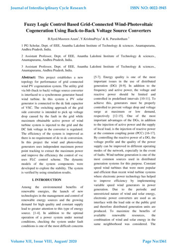
This article has been accepted for publication in a future issue of this journal, but has not been fully edited. Content may change prior to final publication. Citation information: DOI 10.1109/TSTE.2019.2890828, IEEETransactions on Sustainable Energy5most dominant Eigenvalues and hence drive the transientperformance of the hybrid system. Moreover, the state of theac voltage controller of the VSI, i.e., 𝜑9Žj , has a significantimpact on the system stability. However, the migration of thedominant modes is less likely to occur because their locationis correlated to the controllers parameters which are typicallyconstant under different modes of operation.TABLE I. EIGENVALUES OF THE PROPOSED HYBRID SYSTEMEIGEN VALUESINFLUENCING STATE(S)𝜆 2148.6 𝐼A4𝜆% 0.52 𝛾24 𝐼'9𝜆5 6.7 10 𝜆µ,” 56.78 𝑗42100 𝐼t4 , 𝐼tN , 𝑣o4 , 𝑣oN𝜆 ,· 62.46 𝑗41400 𝐼t4 , 𝐼tN , 𝑣o4 , 𝑣oN% 𝐼j4 , 𝑉4j𝜆 8460 𝐼jN𝜆¹ 4180 𝐼AN𝜆 º 2130%𝜆 , % 139.24 𝑗59.93 𝜑94j , 𝑉4j𝜆 5 162.31 𝛿𝜆 µ 18.93 𝜔?𝜆 ” 20 𝜑}𝜆 2.45 𝛾A𝜆 · 0.087 𝜑9Žj 𝛾2N𝜆 0.52 𝜑24 , 𝜑2N𝜆 ¹ 10 𝜑24 , 𝜑2N𝜆%º 10B. Influence of the 𝑀𝑃𝑃𝑇1 and 𝑀𝑃𝑃𝑇AReferring to Figs. 2-3, the variation range of the optimalspeed (𝜔? ) and dc-voltage (𝑉4j ) to maintain the maximumpower extraction at different wind speeds and solar irradiancelevels is 0.501-to-1.0p.u. and 0.997-to-1.012p.u., respectively.As expected from the participation factor analysis in Table I,%the states 𝑉4jand 𝜔? influence the relatively highlydamped Eigenvalues, i.e., 𝜆 , % and 𝜆 µ , respectively.Therefore, the variations of the operating points following theMPPT1 and MPPTA has a minimal influence on the systemstability.IV. EVALUATION RESULTSA time-domain simulation model for the hybrid system inFig. 1 is developed under the Matlab/Simulink environmentto evaluate the validity and the performance of the system.The wind and PV generators are rated at 2.0 and 0.9 MVA,respectively. The complete model entities are built using theSimPowerSystem toolbox. The VSCs are simulated usingaverage-model-based blocks. The simulation type is discretewith a sample time of 50 µs.In the following subsections, the proposed wind-PV cogenerator is subjected to theoretical challenging operatingconditions which might not occur in the realty, e.g., large stepvariations in the wind speed and the solar irradiance levels,and three-phase-to-ground (3PG) faults conditions. Theseworst-case scenarios are applied to challenge the systemstability and show the effectiveness of the designedcontrollers.A. Small-Signal Model VerificationThe accuracy of the small-signal state-space model in (17)is validated in Fig. 4 following a 5% step increase in 𝑉4j at𝑡 1.0 s. In this particular scenario, a lightly dampedresponse has been induced by increasing the bandwidth of thedc-link voltage controller of the VSI so that the model can beeasily validated.For an eigenvalue 𝜆 𝜎 𝑗𝜔Â , the frequency ofoscillation is 𝜔Â [in rad/s] whereas the envelope of theoscillatory response decays following the exponentialfunction 𝐴exp ( 𝜎𝑡), where 𝐴 is the amplitude of theoscillation and 𝑡 is the time in seconds. The yielded dominantlightly-damped mode is 𝜆 73.03 𝑗251.7. Referring toFig. 4, the frequency of the oscillation of the lightly-dampedresponse is 247.4 rad/s whereas the oscillatory responsedecays following a close match to 𝐴exp ( 73.03𝑡). Thisimplies the accurate development of the small-signal model in(17).B. Wind-PV CogenerationThe cogeneration of the wind and PV energy isinvestigated following different weather conditions. As shownin Fig. 5, the wind speed increases from 8.4 to 10.8, thendrops to 7.2, and finally increases to 12m/s at 𝑡 2, 4, and 6s,respectively. The solar irradiance level decreases from 1 to0.8, and then to 0.4, and finally increases to 0.6𝑘𝑊/𝑚% , at𝑡 3, 5, and 6s, respectively.Following Figs. 2-3, the MPPT1 and MPPTA generate the . The corresponding variables are thenoptimal 𝜔? and 𝑉4jregulated using (4) and (12), as shown in Figs. 6(a)-(b),respectively. During the entire operating range, both 𝜔? and𝑉4j are highly damped which is reflected on the generatedwind and PV power as depicted in Figs. 6(c)-(d), respectively,and the injected current to the utility-grid as in Fig. 6(e).For further investigation, the maximum wind power, i.e.,2MW, and a PV power of 0.568MW are generated at 𝑡 6.0 s where the dc-link stability is preserved with a maximumovershoot of 0.06 p.u. as shown in Fig. 6(b). Under allconditions, a unity PCC voltage is maintained following (14),as shown in Fig. 6(f).The designed vector controllers for the VSR and the VSIdo not saturate the generated PWM, as shown in Figs. 6(g)(h), respectively, where the variable frequency operation ofthe VSR is clearly noted.C. Wind-Only GenerationDuring the night-time or at low-irradiance conditions, thePV generator provides a zero power to the utility-grid. Underthis condition, the dc-link voltage is regulated to the minimumvalue. As shown in Fig. 7(a), the dc-link voltage drops to0.858p.u. at 𝑡 2.0 s as the PV power generation drops to 0,and is restored back to 1.0 p.u. at 𝑡 3.0 s when the PVpower is generated. The corresponding wind and PV power aswell as the injected ac current to the utility-grid are shown inFigs. 7(b)-(c), respectively. Note that a blocking diode isusually connected in series with each PV string to preventreverse current flow at the low irradiance levels.D. PV-Only GenerationThe wind speed is assumed to be less than the cut-offspeed, and hence the majority of the generated wind power isconsumed in the system losses. Therefore, the PMSG operatesin the braking mode and the rotor is brought to a stand-still bymechanical means.1949-3029 (c) 2018 IEEE. Personal use is permitted, but republication/redistribution requires IEEE permission. See http://www.ieee.org/publications standards/publications/rights/index.html for more information.
This article has been accepted for publication in a future issue of this journal, but has not been fully edited. Content may change prior to final publication. Citation information: DOI 10.1109/TSTE.2019.2890828, IEEETransactions on Sustainable Energy6Fig .4. The step response of the dc-link voltage to verify the developed smallsignal model in (17).Fig. 5. Wind speed and solar irradiance levels.(a)(b)(c)(d)(e)(g)Fig .6. Performance of the wind-PV cogeneration scenario.As shown in Fig. 8(a), the rotor speed (𝜔? ) drops from 1 p.u.to 0, and then increases back to 1p.u. at 𝑡 2 and 3s,respectively. This corresponds to a sudden change in thegenerated wind power and injected grid current as shown inFigs. 8(b)-(c), respectively. In spite of the challenging operatingscenario, the system stability is maintained.E. Wind-PV Cogeneration under Faults ConditionsConverter-based distributed generation units roughlycontribute by the rated currents under the short circuitconditions. Therefore, and due to the increased penetration ofthe renewable energy resources to the electrical grids, someutilities have enforced the fault-ride through of powerconverters [33]. Accordingly, the distributed generation unitsmust not disconnect during fault conditions with a voltage drop(f)(h)down to 0 p. u. that continues to less than or equal to 150 ms (9cycles for 60Hz systems).In this operational scenario, the proposed wind-PVcogeneration system is investigated for the fault-ride-throughcapabilities. The PCC in Fig. 1 has been subjected to a 3PGfault at 𝑡 4 s for 4.0 cycles. Further, the VSCs have beenimplemented in the Simulink model using pulse-widthmodulated switching blocks.Fig. 9 shows the performance of the dc-link voltage and theutility-grid current under the 1.0 p.u. and 0.5 p.u wind powergeneration whereas the PV power generation is maintained at1.0 p.u.1949-3029 (c) 2018 IEEE. Personal use is permitted, but republication/redistribution requires IEEE permission. See http://www.ieee.org/publications standards/publications/rights/index.html for more information.
This article has been accepted for publication in a future issue of this journal, but has not been fully edited. Content may change prior to final publication. Citation information: DOI 10.1109/TSTE.2019.2890828, IEEETransactions on Sustainable Energy7(a)(a)(b)(b)(c)Fig .7. System performance at the wind-only generation scenario.At 1.0 p.u. wind and PV power generation, and followingthe clearance of the 3PG fault, the dc-link voltage stability
ideal distribution medium in the ac-dominated power systems. Up to the authors' best knowledge, the combination of the grid-connected wind-PV systems has been solely addressed in [15]. The system in [15] comprises a BtB VSCs to interface the PV and wind generators to the utility-grid. On the machine-side-