Transcription
Journal of Interdisciplinary Cycle ResearchISSN NO: 0022-1945Fuzzy Logic Control Based Grid-Connected Wind-PhotovoltaicCogeneration Using Back-to-Back Voltage Source ConvertersB.Syed.Masreen Azam1, Y.KrishnaPriya2 & K. Purushotham 31 PG Scholar, Dept. of EEE, Anantha Lakshmi Institute of Technology & sciences. Anantapuramu,Andhra Pradesh, India.2 Assistant Professor, Dept. of EEE, Anantha Lakshmi Institute of Technology & sciences.,Anantapuramu, Andhra Pradesh, India.3 Assistant Professor, Dept. of EEE, Anantha Lakshmi Institute of Technology & sciences.,Anantapuramu, Andhra Pradesh, India.Abstract: This project establishes a newtopology for performance of grid connectedwind PV cogeneration system. The utility gridvia btb (back to back) voltage source converteris interfaced to a synchronous generator basedwind turbine. In this system a PV solargenerator is connected to the dc link capacitorof VSC. The switching approach of the gridside converter is intended to pick up voltagedrop caused by the fault in the grid whilemaximum obtainable active power of windturbine system is injected to the grid and theDC link voltage in the converter is regulated.The efficiency of the system is improved asthere is no requirement of dc to dc conversion.In this project the wind and photovoltaicgenerators uses independent maximum powerpoint tracking to extract the maximum powerand improve the efficiency the control of vscuses FLC control scheme. The dynamicmodels of the system components weredeveloped to explore the stability. The systemis verified by using simulation results.I. INTRODUCTIONAmong the environmental benefits ofrenewable energies, the launch of newtechnologies in the management and control ofrenewable energy sources and the growingdemand for high quality and constant supplylead to greater attention to this type of energysource. [1-4]. In addition to the optimaloperation of a power system under normalconditions, checking the system under faultconditions is one of the most difficult concernsVolume XII, Issue VIII, August/2020[5-7]. Energy quality is one of the mostimportant issues in the use of distributedgeneration (DG) [8-9]. In addition to thefrequency and active power, the voltage andreactive power should be limited andcontrolled in predefined intervals [10-11]. Toachieve this, generators must be properlycontrolled to prevent voltage drop and voltagesurge at maximum or low demand,respectively [12-15]. One of the mostimportant advantages of the DGs, in additionto the injection of active power and the supplyof local load, is the injection of reactive powerat the common coupling point (PCC) [16-17].By controlling the reactive power of a DG, thevoltage profile and the quality of the powersupply can be improved in different operatingmodes of the network, especially in the eventof faults. Wind turbine generation is one of themost common sources used in distributedgeneration systems for this purpose. Constantspeed wind turbines that were more popularand efficient than recent wind turbine systemswhere electronic power technology has helpedto improve efficiency by implementingvariable speed wind generators in powergeneration. Due to the periodic andunrestricted nature of wind and solar energy,electronic power converters are used as aninterface with the load side or the public gridand therefore distributed generation units areproduced. To maximize the benefits ofavailablerenewableresources,thecombination of wind and solar energy in thesame neighborhood was considered. ThePage No:1361
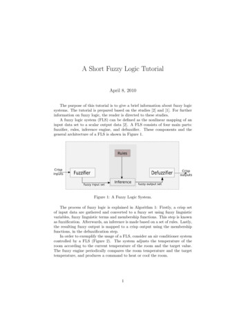
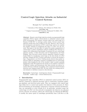
Journal of Interdisciplinary Cycle Researchcogeneration of wind and solar energy has thefollowing characteristics; 1) The availability ofwind and solar energy is generallyharmonizing, and therefore the combination ofboth forms of energy increases the overallefficiency provided. 2) The combination ofwind and solar co generator optimizes the useof land resources and therefore improvescapital investments. 3) Compared to n systems are more dynamicallyable to support the public grid due to themoment of inertia available in the mechanicalsystem of wind generators [8]. 4) Having twosources of energy increases the reliability ofthe generation. One of the most important ofthe significant investigations in the VSWT isthe request for different control schemes forsome purposes in the plant. Help is needed forsome techniques with VSWT control. Due tothe efficient and economic use of renewableenergies, some of the renewable energyresources are integrated, such as the windturbine and the solar array. Due to thedependence on wind speed and solar radiationin such systems, its reliability in meeting loaddemands decreases in all conditions.Therefore, some studies propose thecombination of a diesel generator as a backupsystem and wind / solar power generationsystems. The proposed system is designed toobtain the maximum energy captured by thewind generator / solar array and deliver it tothe electricity grid.Table1MPPTPhotovoltaic SystemComparisonVolume XII, Issue VIII, August/2020forISSN NO: 0022-1945On photovoltaic framework a front-endsupport converter will be by and large obligedtowards the center about inverter will matchthe load prerequisites. Previously, such DCAC alternately DC-DC AC energy converters,there will be An likelihood for FETs) of the same leg(s) fromclaiming inverter because of EMI effect,inappropriate terminating of switches,aggravation out breaking and nonattendance ofcross conduction security inside the gatedrivers itself and so on. This prompts shortingfrom claiming wellspring alternately dcconnection capacitor through the shorted leg(s)of inverter, causing a large current flow anddamage to the system.II. PROPOSED SYSTEM DESCRIPTIONFig.1 The proposed wind-PV cogenerationsystem.The proposed hybrid power generation systemis illustrated in Figure 1. This system consistsof a horizontal axis and a variable speed windturbine, a solar generator, a synchronousgenerator with permanent magnets.1. Grid-Side Voltage source convertercontrol:Most inverters operate as a current sourceby injecting a sinusoidal current and inphase with the mains voltage, with apower factor equal to or very close to theunit. The inverter must be synchronizedwith the fundamental component of thegrid voltage, even in cases where the gridvoltage is distorted or unbalanced or whenthe grid frequency varies. Figure 1 showsanexampleofsteady-statePage No:1362
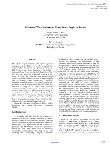
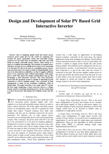
Journal of Interdisciplinary Cycle Researchsynchronization for a three-phase system,inwhichthethree-phasewindphotovoltaic cogeneration system withloadISSN NO: 0022-1945the optimal value of the rotor speed based onthe mechanical characteristicsFig 3: VSR side controlIII. Results and Discussion:1500lightly dampedhighly dampedexponenetial14801460Vdc (V)Fig. 2 VSI side converter controlAs shown in Fig. 1, the ac-side of the VSI isterminated by an inductive filter (𝐿f) with aninternal resistance (𝑅f) and a shunt capacitor(𝐶f). The 𝐿f-𝐶f filter and the utility-gridimpedance are modeled as following;14401420140013800.98To avoid VSI over modulation, the design of aPV array should take into account thecoordination between the MPPT voltage of thePV array and the actual voltage at the commoncoupling point (PCC), i.e. 𝑣o, at general levelsof irradiation. In power converters, the pulsewidth modulation (PWM) and the switchingmodel are dictated by the relationship betweenAC and DC voltage such that Vc mVdc / 2where where is the complex vector modulationsignal. Since Vc is relatively constant andtherefore in steady-state conditions, anysignificant variation in dc could inducemodulated operation or improper use of theDC connection, which in turn degrades thequality of the energy injected into the publicnetwork.2. Machine-Side Voltage SourceRectifier (VSR): At any wind speed, there isan optimal mechanical rotor speed valuewhich corresponds to the generation ofmaximum wind energy. The RSV in Fig. 3obtains the extraction of the maximum windenergy. The MPPT algorithm for the windgenerator uses the wind speed (𝑣1) to generateVolume XII, Issue VIII, August/202011.021.04time(s)1.061.081.1Fig.4 The step response of the dc-linkvoltage to verify the developed small signalmodelThe precision of the small signal statespatial model is validated in Fig. 4 after a 5%increase in 𝑉dc at 𝑡 1.0 s. In this particularscenario, a slightly damped response wasinduced by increasing the voltage controllerbandwidth of the VSI DC link so that themodel can be easily validated.Fig 5. Wind speed and solar irradiancelevelsThe cogeneration of wind and photovoltaicenergy is studied according to the differentclimatic conditions. The wind speed increasesto 12 m / s at 𝑡 2, 4 and 6 s, respectively. Thelevel of solar radiation decreases from 1 to 0.8,then to 0.4 and finally increases to 0.6 𝑘𝑊 /𝑚2, respectively at 𝑡 3, 5 and 6 s.Page No:1363
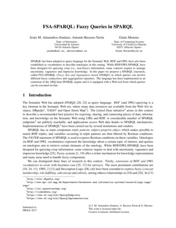
Journal of Interdisciplinary Cycle ResearchISSN NO: 0022-1945Fig a PMSG speedFig f PCC voltageFig b VdcFig g VSR modulationFig c Wind powerFig h VSI modulationFig d PV powerFig e Grid currentVolume XII, Issue VIII, August/2020Fig.6. Performance of the wind-PVcogeneration scenarioFor the entire operating range, both 𝜔r and𝑉dc are strongly damped, which is reflected inthe wind and photovoltaic energy generated asshown in Figs. 6 (c) - (d), respectively, and thecurrent fed into the public network as in Fig. 6(e).For further details, the maximum wind power,i.e. 2 MW, and a photovoltaic power of 0.568MW are generated at 𝑡 6.0 s, where thestability of the intermediate circuit ispreserved with a maximum exceeding of 0.06p.u. as shown in Fig. 6 (b). In all conditions, avoltage of the PCC unit is maintained byfollowing (14), as shown in Fig.6(f). ThePage No:1364
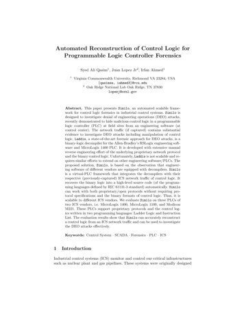
Journal of Interdisciplinary Cycle Researchdesigned vector controllers for the VSR andthe VSI do not saturate the generated PWM, asshown in Figs. 6(g)-(h), respectively, wherethe variable frequency operation of the VSR isclearly noted.Wind onlyISSN NO: 0022-1945p.u. at 𝑡 3.0 s when photovoltaic energy isgenerated. The corresponding wind andphotovoltaic energy, as well as the alternatingcurrent introduced into the public grid, areshown in Figs. 7 (b) - (c), respectively. Notethat a blocking diode is generally connected inseries with each PV string to prevent reversecurrent flow at low levels of radiation.Solar onlyFig a VdcFig a PMSG speedFig b PowerFig.c. Grid currentFig 7. System performance at the wind-onlygeneration scenarioDuring the night or in low irradiationconditions, the photovoltaic generator supplieszero energy to the public grid. In thiscondition, the intermediate circuit voltage isset to the minimum value. As shown in Figure7 (a), the intermediate circuit voltage drops to0.858 p.u. at 𝑡 2.0 s when the photovoltaicpower generation drops to 0 and returns to 1.0Volume XII, Issue VIII, August/2020Fig b PowerFig c .Grid currentFig .8. System performance at the PV-onlygeneration scenarioAs shown in Fig. 8(a), the rotor speed (𝜔r)drops from 1 p.u. to 0, and then increases backto 1p.u. at 𝑡 2 and 3s, respectively. Thiscorresponds to a sudden change in thegenerated wind power and injected gridcurrent as shown in Figs.8(b)-(c), respectively.In spite of the challenging operating scenario,the system stability is maintainedPage No:1365
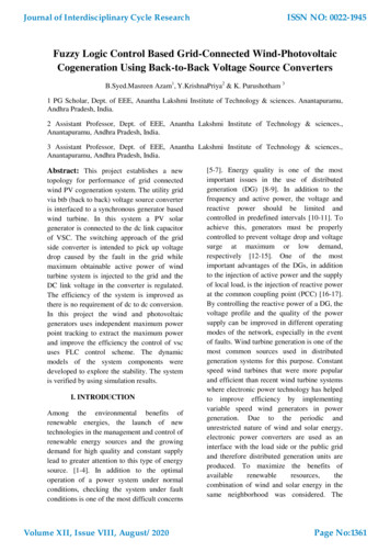
Journal of Interdisciplinary Cycle ResearchISSN NO: 0022-19453phase ground20001.0 PU0.5 PUVdc (V)150010005003.83.944.14.2time(s)4.34.44.541x 101.0 PU0.5 PU0.80.60.4Iga (A)0.2protections are implemented in 1.0 p.u. windand photovoltaic power generation. Theincrease in the intermediate circuit voltage hasbeen limited, while the AC current fed into thenetwork remains stable. The conduction errorwas achieved by electricity dissipate additionalwind energy in the braking resistor until theinput of wind energy is mechanicallyeliminated by checking the angle ofinclination.Forfurtherdetails,theperformance of the system in single-phaseearth fault conditions (1PG) is examined inFig. 11. It is clear that the 1PG fault is notharmful to the system performance comparedto 3PG faults. SCR has been reduced to 4.0and 2.3 to challenge the interconnectedconverter, as shown in Figure 12.0-0.2-0.4-0.6-0.83.944.14.2time(s)4.34.4Fig. 9. The system response to a 3PG faultat 𝑡 4.0 s for 4.0 cycles – 1.0 and 0.5 p.u.wind power generation with 1.0 p.u. PVpower generationFault conditions are associated with asudden drop in PCC voltage which makes itdifficult to transfer maximum power from theDC link to the network. Since the input windenergy is powered by a relatively slowmechanical system, the wind generatorcontinues to inject the maximum wind powerinto the intermediate circuit capacitor duringfault conditions. Therefore, the input power ofthe intermediate circuit becomes significantlyhigher than the output power, and therefore thevoltage of the intermediate circuit increases, asshown in Figure 9 (a) [at 1 pu wind energy].On the contrary, the photovoltaic array doesnot contribute to the instability of theintermediate circuit voltage in fault conditions.The increase in the intermediate circuit voltagepushes the operating point of the photovoltaicfield beyond the point of maximum power. Asshown in Fig. 3, since the voltage of thephotovoltaic field exceeds the MPPT operatingpoint, the photovoltaic power generatednaturally decreases and therefore thephotovoltaic field does not contribute to thefault currents. The photovoltaic generator hasself-regeneration capacity in the faultconditions of the public grid. Figure 10 showsthe system performance when the above faultVolume XII, Issue VIII, August/20204.5Fig a VdcFig b Grid currentFig. 10. The system response to a 3PG faultat t 4.0 s for 4.0 cycles – 1.0 p.u. wind andsolarpowergenerationwiththeimplemented fault protection schemes1800NO PROTECTIONWITH PROTECTION170016001500Vdc 34.44.5Fig. 11. The system response to a 1PG faultat t 4.0 s for 4.0 cycles – 1.0 p.u. wind andPage No:1366
Journal of Interdisciplinary Cycle Researchsolar power generation with and withoutthe fault protection schemes.ISSN NO: 0022-1945Case 11700-------2.3-----4165016001550Vdc e(s)1.21.251.3Fig a PMSG speedFig. 12. The dc-link voltage response atdifferent values of SCR – 1.0 p.u. PV powerand a step change of the wind power from0.5 to 1.0 p.u. at 𝑡 1s.2-------1.25cf-----1.5cf1.51Iga (A (PU))0.50-0.5-1-1.5-21.95Fig b 52Fig. 13. The PCC voltage response atdifferent values of SCR– 1.0 p.u.PV power and a step change of the windpower from 0.5 to 1.0 p.u. at 𝑡 1s. Under thesame operating conditions, the influence ofvariations on the PCC voltage is studied inFig. 13. As shown, the THD of the PCCvoltage increases from 0.05% to 9.8% at 1.25and 1.5𝐶o respectively. Despite the use ofsimple PI controllers for the proposed system,the results in Figs. 12-13 indicate a reasonablerobustness with respect to parameter changes.Using Fuzzy logic control:Rules used:Fig c Wind powerFig d PV powerVolume XII, Issue VIII, August/2020Page No:1367
Journal of Interdisciplinary Cycle ResearchISSN NO: 0022-1945Wind only:Fig e Grid currentFig a VdcFig b PowerFig f PCC voltageFig g VSR modulationFig.c. Grid currentFig 15 System performance at the windonly generation scenarioSolar only:Fig a PMSG speedFig h VSI modulationFig 14 Performance of the wind-PVcogeneration scenarioVolume XII, Issue VIII, August/2020Page No:1368
Journal of Interdisciplinary Cycle ResearchISSN NO: 0022-194541x 101.0 PU with fuzzy logic controller0.80.60.4Iga e(s)Fig b PowerFig b Grid current phase[A]Fig 17 The system response to a 3PG faultat 𝑡 4.0 s for 4.0 cycles1900WITH PROTECTION1800Vdc (V)1700Fig c grid current160015001400Fig .16. System performance at the PV-onlygeneration 2000Fig 18 The system response to a 1PG fault1800at t 4.0 s for 4.0 cyclesVdc (V)160014001.0 PU with fuzzy logic ime(s)Fig a VdcFig. 19. The dc-link voltage response atdifferent values of SCR-4 p.uVolume XII, Issue VIII, August/2020Page No:1369
Journal of Interdisciplinary Cycle ResearchISSN NO: 0022-1945Fig bFig 21THD of PCC voltage using PIcontroller and fuzzy controllerV. CONCLUSIONThisprojectcogenerationThe PCC voltage response of 𝐶f. 2.5Fig 20 The PCC voltage response atdifferent values of 𝐶f gVSCBtBconnected to the vector-controlled network.The VSR on the side of the wind generator isresponsible for extracting the maximum windenergy after changes in wind speed. On theBy verifying the above results the by usingfuzzypresentedsystemperformance is improved and the influenceof the variations of 𝐶f on the PCC voltageis investigated in Fig. 21 .As shown, theutility side, the functions of the VSI are toextract the maximum PV power from the PVgenerator, to achieve a balance between theinputandoutputpowersthroughtheintermediate circuit capacitor and to maintaina PCC voltage of the unit in different mode. of𝑇𝐻𝐷 of the PCC voltage increases fromoperation. The proposed system has the0.05 to 9.8 at 1.25 and 1.5𝐶f, respectively,following advantages; 1) Maximum reliabilityin spite of using simple PI controller. Byand efficiency thanks to the combination ofusing fuzzy controller it is reduced i.e. 0.9windandphotovoltaicgenerators.2)independent MPPT extraction since VSR andVSI are the only ones responsible for theextraction of wind and photovoltaic energy,respectively 3) simple system structure andcontroller design. 4) Bankruptcy can beachieved through existing protection systems.Optimal performance has been reported usingtime domain simulation results in the Matlab /Fig aVolume XII, Issue VIII, August/2020Simulink environment.Page No:1370
Journal of Interdisciplinary Cycle ResearchISSN NO: 0022-1945REFERENCES[9] M. Meiqin, S. Jianhui, L. Chang, Z.[1] F. Giraud, “Analysis of a utility-interactiveGuorong and Z. Yuzhu, “Controller for 1kW-wind-photovoltaic hybrid system with battery5kW wind-solar hybrid generation systems,”storageCanadian Conf. on Electrical and Computerusingneuralnetwork,”Ph.D.dissertation, Univ. Mass., Lowell, 1999.Engineering, Niagara Falls, ON, pp. 1175-[2] F. Blaabjerg, Z. Chen, and S. B. Kjaer,1178, 2008.“Power electronics as efficient interface in[10] A. Yazdani and P. P. Dash, "A controldispersed power generation systems,” IEEEmethodology and characterization of dynamicsTrans. Power Electron., vol. 19, no. 5, pp.for a photovoltaic (PV) system interfaced with1184-1194, 2004.a distribution network," IEEE Trans. Power[3] S. Daniel and N. Ammasai Gounden, “ADel., vol. 24, no. 3, pp. 1538-1551, 2009.novel hybrid isolated generating system based[11] D. Salomonsson, L. Söder, and A.on PV fed inverter-assisted wind-drivenSannino,induction generator,” IEEE Trans. Energymicrogrid,” IEEE Trans. Power Del., vol. 24,Convers., vol. 19, no. 2, pp. 416-422, 2004.no. 3, pp.1045-1053, 2009[4] J. Zhang, X. Xie, D. Jiao and Z. Qian,[12] Nicholas Strachan, and D. Jovcic,“Stability problems and input impedance“Stability of a variable-speed permanentimprovement for cascaded power electronicmagnet wind generator with weak ac grids,”systems,” in Proc. APEC, pp. 1018-1024IEEE Trans. Power Del., vol. 25, no. 4,vol.2, 2004.pp.2279-2788, 2010.[5] J. Carrasco et al., "Power-electronic[13] A. Yazdani and R. Iravani, Voltage-systems for the grid integration of renewablesourced converters in power systems –energy sources-a survey," IEEE Trans. Ind.modeling, control, and applications, JohnElectron., vol. 53, no. 4, pp. 1002-1016, 2006.Wiley & Sons, New Jersey, 2010.[6] Y.-M. Chen, Y.-C. Liu, S.-C. Hung, and[14] S. Sarkar and V. Ajjarapu, “MW resourceC.-S. Cheng, “Multi-input inverter for grid-assessmentconnected hybrid PV/wind power system,”conversion system with wind and solarIEEE Trans. Power Electron., vol. 22, no. 3,resources,” IEEE Trans. Sustain. Energy, vol.pp. 1070-1077, 2007.2, no. 4, pp. 383-391, 2011.[7] Mitsubishi, “PV-UD190MF5,” Mitsubishi,[15] S. Bae, and A. Kwasinski, “DynamicSan Francisco, CA, USA, 2007.modeling and operation strategy for microgrid[8] L. Harnefors, M. Bongiorno, and S.with wind and photovoltaic resources,” IEEELundberg, “Input-admittance calculation andTrans. Smart Grid, vo. 3, no. 4, pp. 1867-shaping1876, el for alow-voltagedchybrid energyconverters,” IEEE Trans. Ind. Electron., vol.[16] T. Hirose and H. Matsuo, “Standalone54, no. 6, pp. 3323-3334, 2007.hybrid wind-solar power generation systemapplying dump power control without dumpVolume XII, Issue VIII, August/2020Page No:1371
Journal of Interdisciplinary Cycle ResearchISSN NO: 0022-1945load,”IEEE Trans. Ind. Electron., vol. 59, no.[23] Y. Wang, J. Meng, X. Zhang and L. Xu,2, pp. 988-997, 2012.“Control of PMSG-based wind turbines for[17] S. Shanghavi, W. M. Grady, and B.system inertial response and power oscillationSchwarz, “Evaluating the impact of winddamping,” IEEE Trans. Sustain. Energy, vol.turbine shadows on an integrated wind and6, no. 2, pp. 565-574, 2015.rdsolar farm,” 2012 3 IEEE PES ISGT Europe,[24] A. Radwan, Y. Mohamed, and E. El-Berlin, 2012.Sadaany,[18] A. Radwan, “Modeling, analysis andevaluation of DC-side interactions of voltage-stabilization of converter-dominated powersource inverters interfacing renewable energydistribution grids”, M.Sc. thesis, Univ. ofsystems,” Sustainable Energy, Grids andAlberta, Edmonton, 2012.Networks Journal, vol. 1, pp. 28-44, 2015.[19] L. Nousiainen, J. Puukko, A. Maki, T.[25]Messo, J. Huusari, J. Jokipii. J. Viinamaki, D.Suryanarayana,Lobera, S. Valkealahti, and T. Suntio,“Gridconnected PV-wind-battery-based multi-“Photovoltaic generator as an input source forinputtransformer-coupled bidirectional dc-dcpower electronic converters,” IEEE Trans.converter for household applications,” IEEEPower Electron., vol. 28, no. 6, pp. 3028-Trans. Emerg. Sel. Topics Power Electron.,3038, 2013.vol. 4, no. 3, pp. 1086-1095, 2016.[20] L. Xu, X. Ruan, C. Mao, B. Zhang, and[26] P. E. Bett and H. E. Thornton, “TheY. Luo, “An improved optimal sizing methodclimatological relationships between wind andfor wind-solar-battery hybrid power system,”solar energy in Britain,” Renewable Energy,IEEE Trans. Sustain. Energy, vol. 4, no. 3, pp.o. 87, no. 1, pp. 96-110, 2016774-785, 2013.[27] I. Abdelsalam, G. Adam, B. Williams,[21] A. Hamadi, S. Rahmani, K. Addoweesh“Current source back-to-back converter forand K. Al-Haddad, “A modeling and controlwind energy conversion systems,” IET Renew.of DFIG wind and PV solar energy sourcePower Gener., vol. 10, no. 10, pp. 1552-1561,generation feeding four wire isolated load,”2016.IECON 2013 - 39th Annual Conf. of the IEEE[28] Renewable Energy Policy Network forInd. Electron. Society, Vienna, pp. 7778-7783,the 21st Century, “Advancing the global2013.renewable[22] P. Mitra, L. Zhang, and L. Harnefors,Secretariat, Paris, France, 2017 [Available“Offshore wind integration to a weak grid byOnline].VSC-HVDCpower-[29] P. Shanthi, G. Uma, and M. S. Keerthana,synchronization control – a case study,” IEEE“Effective power transfer scheme for a gridTrans. Power Del., vol. 29, no. 1, pp. 453-461,connected hybrid wind/photovoltaic system,”2014.IET Renew. Power Gener., vol. 11, no. 7, N211005-1017, 2017.Volume XII, Issue VIII, August/2020Page No:1372
Journal of Interdisciplinary Cycle ResearchISSN NO: 0022-1945[30] K. Kant, C. Jain, and B. Singh, “A Hybriddiesel-wind-pvbasedenergygenerationsystem with brushless generators,” IEEETrans. Ind. Inform.,vol. 13, no. 4, pp. 17141722, 2017.[31] A. Merabet, K. Ahmed, H. Ibrahim, R.Beguenane,andA.Ghias,“Energymanagement and control system for laboratoryscale microgrid based wind-pv-battery,” IEEETrans. Sustain. Energy, vol. 8, no. 1, pp. 145154, 2017[32] ABB Solar Inverters, “PVS980,” ABB,2018.Y.KRISHNAPRIYAGraduated B.Tech from Intell college ofEngineering, Anantapuramu. M.Tech in PowerIndustrial Drives (PID) from JNTUEngineering college,in 2010 Anantapuramu.Currently Pursuing P.hD from JNTU &working as Assistant Professor in Dept ofEEE in Ananthalakshmi Institute ofTechnology & Sciences, Anantapuramu515001 ,AP, India. She have 13 years ofexperience in teaching.[33] U. Kalla, B. Singh, S. Murthy, C. Jain andK. Kant, “Adaptive sliding mode control ofstandalonesingle-phasemicrogridusinghydro, wind and solar pv array basedgeneration,” IEEE Trans. Smart Grid, in press.[34] E. Troester, “New German grid codes forconnecting PV systems to the medium voltagepower grid,” in Proc. 2nd Int. Workshop onConcentrating Photovoltaic Power Plant, pp.1 – 4.K.PURUSHOTHAMGraduated B.Tech from Narayana Engineeringcollege, Guduru. M.Tech in Electrical powerSystems(EPS) from SKD Engineering collegein 2012. Currently he is working as AssistantProfessor and Head of EEE Department inAnanthaLakshmi Institute of Technology &Sciences, Ananthapuramu, AP, India. Hisareas of interest are Power Systems and PowerElectronics. He have 8 years of experience inteaching. He has published 8 internationaljournals.B.SYED.MASREEN AZAM had graduatedwith B.Tech Degree from AnanthalakshmiInstitute of Technology & Sciences,Anantapur, A.P., in the stream of EEE in 2017,currently she is pursuing M.Tech in ElectricalPower Systems (EPS) from Ananthalakshmiinstitute of Technology & Sciences,Anantapuramu-515001, AP ,India. Her areasof interest are Power System and Powerelectronics.Volume XII, Issue VIII, August/2020Page No:1373
the wind and photovoltaic energy generated as shown in Figs. 6 (c) - (d), respectively, and the current fed into the public network as in Fig. 6 (e). For further details, the maximum wind power, i.e. 2 MW, and a photovoltaic power of 0.568 stability of the intermediate circuit is preserved with a maximum exceeding of 0.06