Transcription
MASTERWater Conditioning Corp.Installation and Operation ManualMCA Combination SeriesResidential UnitsFebruary 2011
Table of 23TopicDescriptionModel # and PackagingComponent PackagingDescriptionSystem MediaCombination SystemCombination Tank LoadingMCA Control ValveMCA Control Valve, cont’dService & Drain Piping,General Installation LayoutSystem SchematicElectrical SupplyBrine Tank / Brine TubingFilling Combo with WaterPackaging InformationPackaging DescriptionMCA Control Valve TimerMCA Control Valve Timer cont’dFinal CheckManual oubleshootingTroubleshootingTroubleshootingERR TroubleshootingValve Parts ListValve Parts ListValve Parts ListValve Parts ListValve Parts ListValve Parts ListWarrantyMedia PackagingSystem PositioningFilling with MediaAttaching Valve to TankAttaching Valve to TankDrain PipingPiping LayoutElectrical RequirementsBrine tank connectionDetails for Filling Combo Tank withWaterSetting the MCA TimerSetting the Timer cont’dFinal Installation CheckInstructions for Manual RegenerationBypass OperationSymptom / Cause / SolutionSymptom / Cause / SolutionSymptom / Cause / SolutionSymptom / Cause / SolutionSymptom / Cause / SolutionError TroubleshootingPart Numbers ListPart Numbers ListPart Numbers ListPart Numbers ListPart Numbers ListPart Numbers ListWarranty
Installation and Operating Instructions forMCA CONTROLTop Mount Combination UnitsModel TIron Filter/SoftenerNeutralizer/SoftenerCarbon Filter/SoftenerShipping Carton Description / unit:# ofContentsDescriptioncartons1Mineral tankDistributor pipe installed1Brine tank464 shutoff valve assembly. *NOTE:MCA valve is shipped in brine tank.1MCA controlMCA timer and backwash flow controlvalveand bypass with 1” copper or pvcconnectionC-8001-cubic foot boxesC-800½- cubic foot boxes*Note:The 10-30 units have Vortech and do not require gravel.Filter Media is Packaged as Follows:Model #GravelCFES-20TN/ACFES-30TN/ACFES-40T30 lbs.CNS-20TN/ACNS-30TN/ACNS-40T30 lbs.CTS-20TCTS-30TCTS-40TN/AN/A30 lbs.NOTE:Media½ CF Birm1 CF Birm1 CF Birm1/2 CF NS Mix½ CF Calcite1/2 CF NS Mix½ CF Calcite1/2 CF NS Mix½ CF Carbon1 CF Carbon1 CF CarbonTHIS Combination unit IS NOT INTENDED TO BE USED FOR TREATING WATER THATIS MICROBIOLOGICALLY UNSAFE OR OF UNKNOWN QUALITY WITHOUTADEQUATE DISINFECTION WHETHER BEFORE OR AFTER THE SYSTEM.1
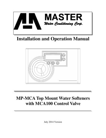
Water Softener Positioning:1. Place combination unit in desired position, far enough from walls andother obstructions to allow for servicing the unit.2. Place the combination unit within reasonable access to a grounded115V/60 HZ circuit and a legal drain line connection.Combination Unit Tank Loading: (10/20/30 units have a vortechdistributor and do not require gravel)(C-800 is pre-loaded in bottom tank)1. Remove yellow caplug from top of tank. DO NOT CUT white risertube. Tube was prefitted at the factory.2. Center the distributor and make sure it is resting on the bottom of thetank. The top of the distributor pipe will be 5/8” above the top of thetank (this was prefitted at the factory).3. Cover the top opening of the distributor pipe before filling the tankwith media.4. Pour the media provided with the unit into the top of the tank. Seepage one for your specific model number unit to determine theamount of media to load into the mineral tank.5. Remove the material used to cover the top opening of the distributorpipe.MCA Control Valve:1. When facing the front of the MCA timer, the inlet connection islocated on the right and the outlet connection is on the left. Thecontrol valve's inlet and outlet connections are either 1” copper orPVC equipped with gasket and nut.Control ValveFront ViewTop View2
2. Turn the control valve upside down and ensure that the control valvedistributor o’ring is in place. Use silicone lubricant on the o'ring.**DO NOT USE PETROLEUM!****USE ONLY SILICONE **3. Place the control valve onto the distributor pipe and into the tankopening.4. Thread the control valve hand tight . Do not overtighten.5. Locate the bypass valve assembly that is packaged with thecontrol valve. The bypass valve has two red handles thatindicate flow direction, two threaded connections for the tailpiece kit and two o’ring seal connections with nuts for the controlvalve. Align the insert connection ends with o’ring seals andnuts to the inlet and outlet connections of the control valve.Hand tighten the nuts. DO NOT OVERTIGHTEN THE NUT!Bypass ValveControl ValveTail piece assembly6. Locate the tail piece kit that is packaged with the control valve.The standard tail piece kit is 1” copper with optional 1” PVC or ¾”copper kits available as a special order. Each tail piece,o’ring, split ring and nut is presassembled at the factory. Align atail piece assembly to the bypass valve threaded inlet and insertuntil the nut can be tightened. Hand tighten the nut becauseexcessive tightening will damage the assembly. REPEAT THEPROCEDURE FOR THE OUTLET CONNECTION.3
Service and Drain Piping:1. Pipe combination unit into the service lines .The inlet and outletconnections of the control valve are 1” copper or PVC and arelocated on the back of the valve body. As you face the timer the inletis on the right and the outlet is on the left. Always follow localplumbing codes when installing our water treatment equipment.2. If sweat fittings are used, be sure soldering is done in such a manneras not to allow heat to reach the control valve or bypass. (IfSchedule 80 PVC is used make sure to follow the proper primer andsolvent instructions.)3. The drain line connection is 5/8 OD or ¾” npt and is located on thetop left of the valve as you face the timer. It is recommended youinstall a ¾” union on the drain line for servicing. The drain line mustbe of adequate size to allow for full regeneration flow.DRAIN LINECONNECTION The control valve drain connection is 3/4" npt. Never decrease the drain piping size to below drainconnection size. Maximum drain line length is 30 feet. Maximum drain line height is 6 feet above the controlvalve. The drain line must be piped to an open air gap (SeeFigure above) Always follow local plumbing codes.UNDER NO CIRCUMSTANCES SHOULD THERE BE A DIRECTCONNECTION WITH SANITARY SEWAGE FACILITIES.4
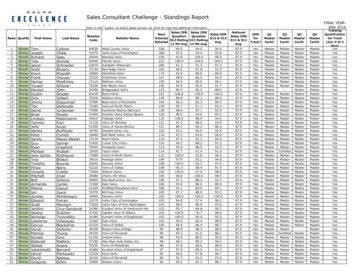
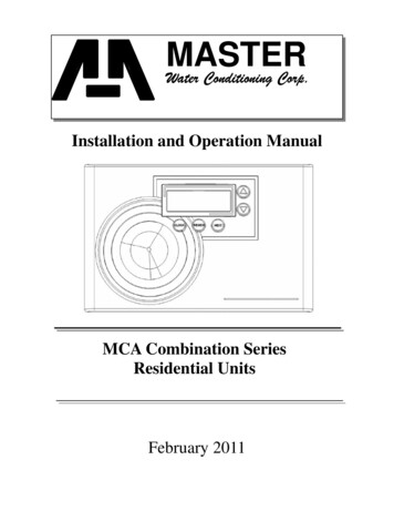
MASTERWater Conditioning Corp.TYPICAL PIPING LAYOUT FORCSERIES COMBINATION UNITTreatedAir Gap DrainOverflowfitting tofloor draingravityUntreatedMaster WaterConditionerWell TankBrine tankNOTE: All Master Water Conditioners must beinstalled after the well tank or water meter if itspublic water supply.5
Electrical Requirements:Always follow all local electrical codes when installing our watertreatment equipment.1. Provide an 115v/60Hz properly grounded dedicated electricalOutlet. (It’s very important that the polarity be correct)Avoid using outlets that are switch controlled.2. Maximum amperage required is 5 amps.3. Make sure the electrical service provides power 24 hours per day.We recommend installing a surge protector to protect unit frompower surges, which are not covered by warranty.Brine Tank:1. The brine tank should be located directly beside the combination unitmineral tank.2. Connect the 3/8" poly tubing to the 3/8” black elbow compressionfitting located on the top left side of the MCA control valve.See Figure Below.BRINE REFILLCONNECTIONIf the brine tank is equipped with a shutoff valve, the float heightwas preset at the factory.6
Filling Water Softener with Water:1. Connect the MCA control valve transformer into the electrical outletprovided.2. Press and hold the Up and Down arrows simultaneously for threeseconds until the drive motor starts. When the drive motor stops, thedisplay will read “C1” backwash position.3. Open the inlet ball valve a ¼ turn of its full open position to allowwater to enter the water softener mineral tank slowly. The water isgoing to enter the tank from the bottom of the distributor pipe andleave the tank from the top. This will slowly purge all the air from thetank.IF WATER ENTERS THE TANK TOO FAST, ALL THE CATIONRESIN WILL BE FLUSHED TO DRAIN DURING START UP.4. When only water is running to the drain, open the inlet and outlet ballvalves fully.5. Press the Up button to advance the control valve to the brine/rinseposition. The display will read “C2”.6. Once the drive motor stops, press the Up button to advance thecontrol valve to the fast rinse position. The display will read “C4”.The fast rinse position will rinse the softener tank.7. The control valve will automatically advance to the brine refill positionwhere the brine tank will fill with the proper amount of water. Thedisplay will read “C5”.NOTE: THE TIMER WILL AUTOMATICALLY ADVANCE TO THESERVICE POSITION AND THE DISPLAY WILL READ TIME OF DAY.7
MCA Control Valve Timer Settings:Note: The control valve is set at the factory. You only need to set thetime of day and regeneration time if required, which is preset at 2 am.Time of Day Setting1) Press the CLOCK button. The screen will display “Set Time” andthe hour will be blinking.2) Press the UP or DOWN arrows to adjust the hour —check forcorrect am or pm mode.3) Press the CLOCK button.Time of Regeneration Setting (the factory default is 2 AM)Simultaneously press the CLOCK and the UP arrow for 3 seconds:The screen will display “Set Time Regen” and the hour will beblinking.1) Use the UP or DOWN arrows to adjust hour.2) Press the CLOCK button.Regeneration Frequency Setting (the factory default is every 7 days)The screen will display “Set Regen Day” and the days ofregeneration frequency will be blinking.1) To change the number, use the UP or DOWN arrows.2) Press the CLOCK button.3) Set up is complete and the screen will now show the time.8
Final Check:1. Fill the brine tank with Solar Salt and the Res-Up Feeders with ResUp (one quart is provided).2. Make sure the drain line connection meets all plumbing codes andthat the drain line size can handle the backwash flow rate of thesoftener.3. Make sure the Inlet and Outlet on bypass valve are open.4. Make sure the control valve timer is plugged into an electrical outletwith power 24 hours per day.5. Check all piping for leaks.9
10
TroubleshootingProblem: Water conditioner fails to regenerate. No soft water.Possible CausePower supply to MCA control hasbeen interrupted.Water pressure lost.Corrupted programming of MCAtimer.Defective MCA timer.No salt in brine tank.Manual bypass valve is open.Leak at riser pipe seal.Insufficient brine.Plugged injector or injector screen.SolutionDetermine reason for powerinterruption and correct. Reset time ofday.Restore water pressure.Reprogram timer assembly.Replace timer assembly.Add salt and regenerate.Close manual bypass valve.Insure that riser pipe is properlysealed at o’ring seal. Inspect pipe forcracks.Check brine float height and cleanassembly if necessary. Check flowrate capabilities of safety float and aircheck assembly.Inspect and clean injector and/orinjector screen.Problem: No Brine DrawPossible CausePlugged injector or injector screen.Insufficient water pressure.Corrupted programming of MCAtimer.Defective MCA timer.Obstructed drain line.SolutionInspect and clean injector and/orinjector screen.Increase water pressure above 25psig (172kPa) minimum.Reprogram timer assembly.Replace timer assembly.Remove obstruction.11
Problem: Insufficient brine drawPossible CausePartially clogged injector or injectorscreen.Restricted flow rate in brine line.Insufficient water pressure.Excessive back pressure oninjector due to elevated drain line.Damaged valve disk.Partially restricted drain line.SolutionInspect and clean injector and/orinjector screen assembly.Check flow rate capabilities of thesafety float/aircheck assembly.Increase water pressure above 25psig (172kPa) minimum.Reduce drain line elevation to heightof valve.Replace all valve disks.Remove restriction.Problem: Insufficient Refill to Brine TankPossible CauseBrine refill controlRestricted flow rate in brine line.SolutionRemove and cleanCheck flow rate capabilities of thesafety float/aircheck assembly.Problem: Excessive Water in Brine TankPossible CausePlugged drain line flow control.Plugged injector and/or injectorscreenSolutionClean flow control.Inspect and clean injector and/orscreen.Problem: Loss of Media to DrainPossible CauseNo flow control installed in drainline.SolutionInstall drain line flow control.12
Problem: Leak to DrainPossible CauseNo flow control installed in drainline.Insufficient water pressure.Damaged valve disk or obstructionin valve disk.SolutionInstall drain line flow control.Increase water pressure above 25psig (172kPa) minimum.Inspect and if damaged, replace allvalve disks or remove obstruction.Problem: Loss of Water PressurePossible CauseFouled resin bed due to ironaccumulation.Slots in riser pipe or laterals arefilled with resin fines.SolutionClean control valve and mineral bedwith cleaner.Inspect and clean distributor pipe slotsas needed.Problem: Salt in Water to Service after RegenerationPossible CauseInjector is too small for system size.Brine draw time excessively longdue to low water pressure.Restricted drain line.Insufficient rinse volume.Damaged valve disk.Plugged injector and/or injectorscreen.SolutionInstall correct injectorIncrease water pressure above 25psig (172 kPa) minimum.Remove drain line restriction.Increase slow rinse time, fast rinsetime, or both.Replace all valve disks.Inspect and clean injector and/orinjector screen.13
Problem: Timer does not display time of dayPossible CauseAC Adapter unpluggedNo electric power at outletDefective AC AdapterDefective PC BoardSolutionConnect powerRepair outlet or use working outletReplace AC AdapterReplace PC BoardProblem: Timer does not display correct time of dayPossible CauseSwitched outletPower OutageDefective PC BoardSolutionUse uninterrupted outletReset time of dayReplace PC BoardProblem: Control Valve regenerates at wrong time of dayPossible CausePower OutagesTime of day not set correctlyTime of regeneration incorrectSolutionReset control valve to correct time ofdayReset to correct time of dayReset regeneration timeProblem: Control valve stalled in regenerationPossible CauseMotor not operatingNo electric power at outletDefective AC adapterDefective PC boardBroken drive gear or drive capassemblyBroken piston retainerBroken main or regenerate pistonSolutionReplace motorRepair outlet or use working outletReplace AC adapterReplace PC boardReplace drive gear or drive capassemblyReplace piston retainerReplace main or regenerate piston14
Problem: Control valve does not regenerate automatically when UP andDOWN buttons are held and depressedPossible CauseAC adapter unpluggedNo electric power at outletBroken drive gear or drive capassemblyDefective PC boardSolutionConnect AC adapterRepair outlet or use working outletReplace drive gear assemblyReplace PC boardProblem: Control valve does not regenerate automatically but doeswhen UP and DOWN buttons are depressed and heldPossible CauseDefective PC boardSet-up errorSolutionReplace PC boardCheck control valve set-up procedure15
ERROR CODESDisplayDescriptionCauseE1 (1001)Unable to recognize start ofregenerationDefective motor, damagedwiring, or poor wireconnection.E2 (1002)Unexpected electrical ormechanical stallDefective motor, damagedwiring, poor wire connection,or mechanical componentfailure.E3 (1003)Motor running too long ortimeout during piston relocatingDamaged wiring, poor wireconnection, or mechanicalcomponent failure.E4 (1004)Motor timeout when piston isrelocating to service positionDamaged wiring, poor wireconnection, or mechanicalcomponent failure.(1006)MAV-No Hard Water Bypassmotor ran too long, piston can’tfind proper positionUnplug transformer fromelectrical outlet. After 1minute, connect transformerto electrical outlet.The MAV will synchronize tothe proper position.(1007)MAV-No Hard Water Bypassmotor ran too short, piston can’tfind proper position andmovement is stalledUnplug transformer fromelectrical outlet. After 1minute, connect transformerto electrical outlet.The MAV will synchronize tothe proper position.(1009)Internal software error generatedby detection of an invalid motorstartReplace circuit board.16
17
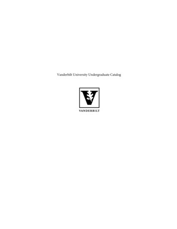
MCA PARTS18
MCA PARTS19
MCA PARTS20
21
22
12 YEAR LIMITED WARRANTYAs of Oct. 1, 1995This Residential Water Conditioner is warranted for a period of one year from date ofpurchase by first user against defects in materials and workmanship. In addition, the completecontrol valve is warranted for five years. The control valve body (excluding internals and electricalparts) is warranted for six years. The mineral tank, plastic brine tank or cabinet tank (excludingmineral) is warranted against rust, corrosion or bursting for a period of twelve years from date ofmanufacture. Except, as specifically set forth in this paragraph, Master Water ConditioningCorporation makes no other warranties, express or implied.This warranty shall be void if the conditioner is moved from the place of original installation,or if damage is caused by misuse, misapplication, accident, freezing, flood, fire or if not installed inaccordance with instructions furnished by Master Water Conditioning Corporation.This warranty shall be void in the event of damages from external sources or where theconditioner has been operated at pressure in excess of 100 pounds per square inch or at a temperaturegreater than 100 degrees F. or less than 32 degrees F. Incidental costs or consequential damages arenot covered by this warranty.All defective parts shall be returned prepaid to Master Water Conditioning Corporation forinspection. Master shall not be liable for labor charges other than Master factory repairs.This warranty gives you specific legal rights, and you may have other rights which vary fromstate to state. Some states do not allow limitations on duration of implied warranties or exclusion ofincidental or consequential damages, so the above limitations may not apply to you.All claims must be submitted in writing to Master Water Conditioning Corporation at 224Shoemaker Road, Pottstown, Pennsylvania 19464 within thirty (30) days from the discovery of thedefect. Master Water Conditioning Corporation thereafter will correct defective parts andworkmanship or rusting, corrosion or bursting within sixty (60) days.Failure to notify Master by completing, signing and returning the registration card withintwenty (20) days of the purchase shall void the warranty.MASTERWater Conditioning Corp.224 Shoemaker Rd. Pottstown, Pa. 19464
MASTER Water Conditioning Corp. Well Tank NOTE: All Master Water Conditioners must be installed after the well tank or water meter if its public water supply. Brine tank Air Gap Drain Overflow fitting to floor drain gravity Untreated TYPICAL PIPING LAYOUT FOR CSERIES COMBINATION UNIT Treated