Transcription
what is anarduino?it’s an open‐sourceelectronics prototypingplatform.what does that mean?open source‐“resources that can be used, redistributed or rewritten free of charge.often software or hardware.”electronics‐“technology which makes use of the controlled motion of electronsthrough different media.”Prototype‐Platform‐“an original Form that can serve as a basis or standard for other things.”“hardware architecture with software framework on which other softwareCan run.”
photocellledmicrochipbreadboardAn Arduino is a microchip, which is a very small computer that you can program to respond tothings. It can measure conditions (like how much light there is in the room). It can controlhow other objects react to those conditions (room gets dark and an led turns on).ONOFFOr it can respond to something assimple as the press of a switch.a mouse is a commoninput devicefor a desktop computer,a monitor is a commonoutput device.Microcontrollers use inputs and outputs Like anycomputer. Inputs capture information From the useror the environment while Outputs do something withthe information that has been captured.
momentary switchforcesensitiveresisitorA switch or A sensor could be An inputinto the Arduino.whats thedifference betweendigital and analoginputs andoutputs?inputs and outputs can be digital or analog.Digital information is binary‐ it is either trueor false. Analog information is continuous, itcan hold a range of values.DC Motorany object we want to turn on and off andcontrol could be An output. It could be amotor or even a computer.Digital informationis discrete andfinite. allinformation isdescribed in twostates, 1 or 0,on or off.Analog informationis characterizedby its continuousnature. it can have aninfinite numberof possiblevalues.a switch is a digital input, a sensor is ananalog input. the range of an analog sensoris limited by its conversion to digital data.
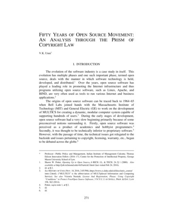
voltage?current?resistance?Ohm’s law?Current (I)Voltage (V)is the amountis a measureof flowof electricalthrough apotential.conductiveIt is measuredmaterial.in volts.It is measuredin amperesBefore we plug in the Arduino,we will review a few termsand principles that have todo with how electricity (andtherefore electronics) works.or Amps.Resistance (R)is a material'sopposition tothe flow ofelectriccurrent.It is measuredin ohms.Electricity is the flow of energy through a conductive material.the speed of flowis determined by voltageresistance increases ordecreases flowamount of flow moving throughpipes is currentthe water analogy is commonly used to explain these terms. Here’s one model.
OHM’s lawcurrent voltage/resistance(i v/r)orResistance voltage/current(r v/i)orVoltage Resistance * current(v r*i)There is a relationship between voltage,current and resistance, discovered by GeorgOhm, a German physicist.for example, Increasethe resistance, lessflow.Lampor increase thepotential, more flow.Current flowSwitchDC power source now let’s look at a simple circuit. everycircuit is a closed loop that has an energysource (battery) and a load (lamp). The loadconverts the elecrical energy of the batteryand uses it up. this one has a switch too.This is a schematic of the same circuit (itrepresents the circuit using symbols for theelectronic components). When the switch isclosed, current flows from the powersource and lights the lamp.
IIDirect Current(DC)Alternating Current(AC)IIThere are two Common types of circuits,Direct Current and Alternating Current.In a Dc circuit, the current always flows inone direction. In AC, the current flows inopposite directions in regular cycles. We willonly talk about Dc circuits here.Now that we’ve reviewed somebasics of how electricityworks, Let’s get back t0the arduino.The arduino will need power to run. we willneed to attach it to a computer to program it.download here:http://arduino.cc/en/Main/SoftwareAttaching the arduino to a computer witha usb cable will supply The 5 volts of powerwe need and allow us to start programming.you’ll have to download and install softwareto program the arduino. it is available fromthe URL above Free of charge. the ARduinosoftware runs on the Mac os X, Windows andlinux Platforms.
for instructions on how to installarduino software on a mac:http://www.arduino.cc/en/Guide/MacOSXFor Instructions on how to installon Windows:http://www.arduino.cc/en/Guide/WindowsFor Instructions on how to installon nuxgo to the URLS above for detailed instructions oninstalling the software on these platforms.Launch the arduino software. in the tools menu,select the board you are using (tools board).for example, Arduino Uno.When you have installed the software,Connect the arduino. An led marked ONshould light up on the board.Next select the serial port.(Tools serial port) On a mac it will besomething like /dev/tty.usbmodem. On awindows machine, it will be com3 or somethinglike that.
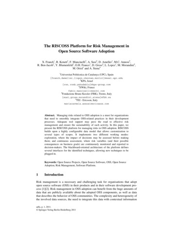
what’s anIntegratedDevelopmentenvironment?When you downloaded theArduino software, youdownloaded an IDE. it combinesa text editor with a compilerand other features to helpprogrammers develop software.The Arduino IDE allows you to write Sketches, or programsand upload them to the Arduino board. open the blink examplein the file menu. File Examples 1.Basics Blink.int ledPin 13;void setup() {pinMode(ledPin, OUTPUT);}Upload buttonvoid loop() {ToSerial.println(analogRead(A0);upload the sketch to the arduino board,clickthe upload button on the strip of}buttons at the top of the window. somemessages will appear in the bottom of thewindow, finally Done Uploading.the led at pin 13 on the arduino starts blinking.
void setup() {// initialize the digital pin as an output.// Pin 13 has LED connected on most Arduino boards:pinMode(13, OUTPUT);}void loop() {digitalWrite(13, HIGH);delay(1000);digitalWrite(13, LOW);delay(1000);}////////set the LED onwait for a secondset the LED offwait for a seconda sketch, like a program writen in anylanguage, is a Set of instructions for thecomputer. If we look closely at the Blinksketch, we see there are 2 major parts,setup and loop.http://arduino.cc/en/Reference/HomePagesetup: happens one time whenprogram starts to runLoop: repeats over andover againThese Are both blocks of code calledfunctions that every sketch will have. Theyare blocked out by curly Braces { }.//DeClares block of codevoid setup() {pinMode(13, OUTPUT); //sets pin 13 to output}//End block of code//declares block of codevoid loop() {digitalWrite(13, HIGH); //sets pin 13 highdelay(1000);//pause 1 seconddigitalWrite(13, LOW);//sets pin 13 lowdelay(1000);//pause 1 second}//End block of codecheck out the arduino website for thearduino reference guide and many otherresources to learn the language.For now, let’s look at this simple script lineby line & see what each line does.
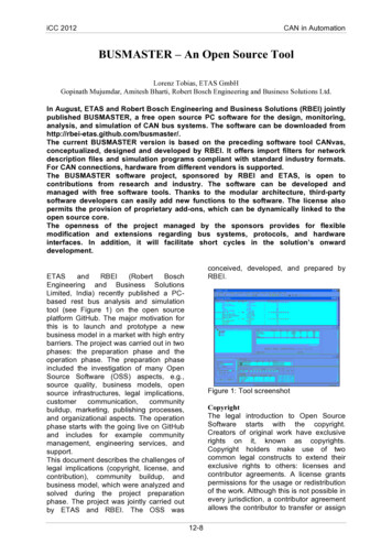
holes connectedhorizontallyholes connectedverticallyHow do we control objects that are not onthe arduino board? we will connect the arduinoto a solderless breadboard. This will allowus to quickly set up and test circuits.This breadboard has 2 rows of holes runningdown the left and right side, and 5 rows ofholes on either side of a middle indentation.the side rows are connected vertically,each Row of 5 holes in the middle areconnected horizontally.anode(connectsto power)cathode(connectsto ground)we will connect power and ground from thearduino board to the vertically connectedstrips on the left and right with 22 gaugewire. other components can be attached tothe holes in the middle and to power andground as needed.When current flows through a led (Lightemitting Diode) in the right direction, itlights up. we’ll attach an LEd to thebreadboard, then to the arduino so we cancontrol it with code.
void setup() {pinMode(2, OUTPUT);}void loop() {digitalWrite(2, HIGH);delay(500);digitalWrite(2, LOW);delay(500);}the anode is connected to pin 2 on the arduino througha 220 ohm resistor. The cathode is connected toground. pins 2 through 13 can be configured as digitalinputs or outputs. click New button to start a sketch.in setup, we set pin 2 to be anoutput. in loop, first we set pin 2high which lights the led. Delaypauses 500 milliseconds, or half asecond. when pin 2 is set low, theled goes off, we pause another halfsecond.verify buttonupload buttonclick verify on the menu to check your code. ifthere aren’t any errors, click upload to putyour program on the arduino.the led blinks on for half a second, thenblinks off for half a second, over and overagain.
Next we will add a switch, a digitalinput, so we can turn the LED offand on.Connect one end of a momentary switch to pin 4 on theArduino, with a 10k resistor connected to groundattached to the same end. Attach the other end topower. We will leave the LED attached to the same pin.void setup() {pinMode(2, OUTPUT);pinMode(4, INPUT);}void loop() {if(digitalRead(4)){digitalWrite(2, HIGH);}else{digitalWrite(2, LOW);}Next we’ll write the code. In setup, we declarepin 2 an output and pin 4 an input. in loop, weuse an if statement, if we read pin 4 as high, weset the led pin to high, otherwise we set theled pin to low, turning it off.The LED lights when the switch is held down.
a potentiometer, or pot, is avariable resistor. the amountof resistance changes as itis turned, increasing ordecreasing depending onwhich direction it isturned.Now we will set up an analog input.We’ll use a potentiometer.Attach the middle pin on the potentiometer to Analog pinA0. attach one end of the pot to power, the other toground.Serial Monitorvoid setup() {Serial.begin(9600);}void loop() {Serial.println(analogRead(A0);}click to openserial windowFirst we will look at the range of values weget by turning the pot using the Serialmonitor. in our code, we initialize the serialobject in setup, setting a baud rate of 9600.In loop, We read the value from analog pin a0and print it to the serial object using theprintLn function,after you have uploaded the script to thearduino, click the Serial Monitor button inorder to see the values as you turn the pot.A window will open, and you will see valuesranging from 0 to 1024 as the pot is turned.
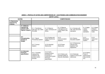
5V0% Duty Cycle - analogWrite(0)0V50% Duty Cycle - analogWrite(127)5V0V100% Duty Cycle - analogWrite(255)5V0VLet’s use the changing values we receive from the potas a dimmer to light an LED. put the led back into theboard, attached to the Arduino at pin 3.We’ll use pulse width modulation(PWM). This is a method of simulatingan analog value by manipulating thevoltage, turning it on and off atdifferent rates, or duty cycles. youcan use pwm with pins 3, 5, 6, 9, 10,and 11.int sensorValue 0;void setup() {pinMode(3,OUTPUT);}void loop() {sensorValue analogRead(A0);analogWrite(3, sensorValue/4);}First we create a variable to store the valueof the pot. In setup we make pin 3 an output.In loop, we store the value we have read frompin a0 in our variable. Then we write the valueto pin 3, our led pin. we have to divide thevariable by 4, so we will have a range of valuesfrom 0 to 255, or a byte.The brightness of the LED changes, rangingfrom completely off to very bright as youturn the pot.
That’s it!This is a very briefintro. in the nextPanels, there arelinks and otherresources. checkthem all out,you’ll find more!LinksSoftwareSoftware uage ppliesSparkfun Electronicshttp://www.sparkfun.com/Adafruit Industrieshttp://adafruit.com/Maker Shedhttp://www.makershed.com/Jameco Electronicshttp://www.jameco.com/TutorialsArduino site eLady gory‐technology/channel‐arduino/booksGetting Started with Arduino by Massimo BanziMaking Things Talk: Using Sensors, Networks, andArduino to see, hear, and feel your world byTom IgoePhysical Computing: Sensing and Controllingthe Physical World with Computers by DanO'Sullivan & Tom IgoeArduino Cookbook by Michael Margolisall text and drawings by Jody Culkinfor more, check out jodyculkin.comSpecial Thanks to Tom Igoe, Marianne petit,Calvin Reid, The faculty and staff of theinteractive telecommunications program atnyu, particularly Dan o’sullivan, Danny rozinand Red burns. thanks to Cindy karasek, chrisStein, sarah teitler, kathy goncharov & zannahmarsh.many, many thanks to the Arduino team forbringing us this robust and flexible opensource platform.and thanks to the lively, active and evergrowing arduino community.
To upload the sketch to the arduino board, click the upload button on the strip of buttons at the top of the window. some messages will appear in the bottom of the window, finally Done Uploading. Upload button The Arduino IDE allows you to write Sketches, or programs and upload them to the Arduino board. open the blink example in the file menu.