Transcription
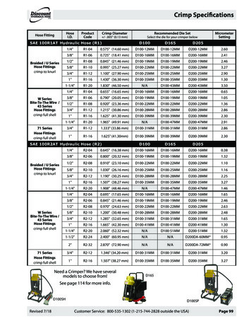
TBO-Quality Crimp HandbookINDUSTRIAL CRIMP QUALITYHANDBOOKOrder No. 64016-0065Doc No: TM-640160065Revision: BRelease Date: 00-00-02Revision Date: 10-16-09UNCONTROLLED COPYPage 1 of 27
TBO-Quality Crimp HandbookTable of ContentsSECTION1Introduction2Purpose and Scope3Definitions and Terms4Associated Materials5Terminal .4.7Visual Inspection of OPEN BARREL CrimpsVisual Inspection of CLOSED BARREL CrimpImportance of Proper Crimping8.1.8.2.8.3.8.4.8.5.9Preparing the WireSetup and Operation of a PressSetup and Operation of a Hand Crimp ToolSetup and Operation of a Air Powered Crimp ToolQuality Crimps7.1.7.2.8Features of Solderless TerminalsBarrel Serration/DimplesBarrel StylesSlicesConditionsTestingTensile ValueElectrical ResistanceCrimp jointsMiscellaneousDoc No: TM-640160065Revision: BRelease Date: 00-00-02Revision Date: 10-16-09UNCONTROLLED COPYPage 2 of 27
TBO-Quality Crimp HandbookSECTION1INTRODUCTION TO CRIMP TECHNOLOGYDeveloped to replace the need to solder terminations, crimping technology provides a high quality connectionbetween a terminal and a wire at a relatively low applied cost. The methods for applying crimp terminations dependon the application, volume, and range from hand-held devices to fully automated systems.The application methods include a basic hand tool, a press and die set, a stripper crimper, or a fully automatic wireprocessing system. However, no matter what method is used, the setup of each tool is critical for achieving aquality crimp.Today, many OEM companies are using Statistical Process Control (SPC) to continuously improve their crimpterminations. Crimp termination is a complex process and to ensure consistent quality it is necessary to understandthe variability and inter-relational interactions that the technology involves.Without a thorough understanding of the crimping process, and all the factors that can affect it, the result may notmeet expectations. The three key elements in the crimping process are the terminal, the wire, and the tooling.TerminalFor most applications, it is not economically practical for connector manufacturers to design a terminal to acceptone wire size, one wire stranding, and one insulation diameter (UL type) as well as Mil Specification. Mostterminals accommodate many wire sizes, stranding, and a range of insulation diameters, and the terminals aredesigned to meet acceptable levels over this entire range.WireThe wire stranding and insulation type can vary widely within one wire size. For example, there is more than 18%more material in an 18 AWG by 19-strand wire than an 18 AWG by 16-strand wire. The insulation diameter of an18 AWG wire can range from 1.78mm (070") to over 4.57mm (180"). Wire strands can be copper, tinned, overcoated, or top coated. Wire insulation materials, thickness, and durometers vary from application to application.ToolingWhat type of tooling does the application require? Does the application require hand stripping of the wire or doesthe volume dictate an automatic wire-stripping machine? Does the application and volume require hand tools,press and die, or fully automatic wire process machines? Crimping with a manual hand tool, semi-automatic pressand die, or fully automatic wire processor, all involve different levels of variability. The terminal, wire, and type ofapplication tooling all affect the quality of the completed terminations.Doc No: TM-640160065Revision: BRelease Date: 00-00-02Revision Date: 10-16-09UNCONTROLLED COPYPage 3 of 27
TBO-Quality Crimp HandbookSECTION 2PURPOSEThis handbook provides general guidelines and procedures for understanding and achieving acceptable crimpterminations. A glossary in Section 3 lists common terms and definitions. Section 4 lists the tools that arenecessary to take accurate measurements and evaluate the crimp's acceptability.For open barrel only, the tooling setup is critical in determining the quality of the finished crimp. The attributes thatneed to be considered include crimp height, conductor brush, bell mouth, cut-off tab and strip length and insulationposition. Variability in one or more of these attributes can reduce the measured pull force. It can be difficult toestablish acceptable variability limits because the attributes all interact with one another.For example, a track adjustment for bell mouth also will change the cut-off tab length and the insulation wireposition while strip length and wire locations affect the conductor brush and insulation position. Adjusting theinsulation crimp height may result in a slight change to the conductor crimp height measurement. It may benecessary for the setup person to make multiple adjustments to establishing an optimal setup.The order in which a setup is done may help reduce the number of repetitions required for an optimum setup.This handbook is structured so that parts, or all, of its contents can be used as a procedural guide for ISOrequirements.SCOPEThis handbook is intended for Molex customers who are crimping Molex open and closed barrel crimpterminals and are using Molex tooling.The handbook's contents may slightly differ from other connector manufacturers' or individual company guidelinesand procedures.This handbook provides a basic overview of what to look for in an acceptable crimp. It is not intended to replaceindividual product and/or tooling specifications.Individual terminals or applications may have special requirements. Tooling limitations also may not permit anattribute to be adjusted to meet optimum requirements.Doc No: TM-640160065Revision: BRelease Date: 00-00-02Revision Date: 10-16-09UNCONTROLLED COPYPage 4 of 27
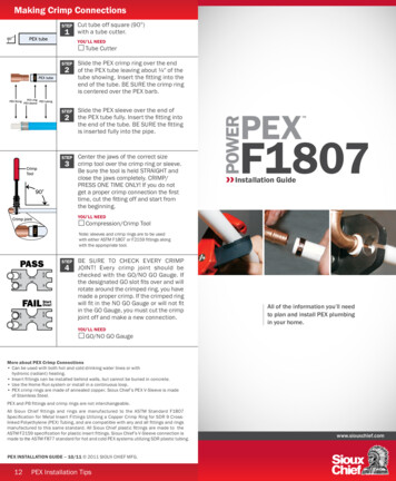
TBO-Quality Crimp Handbook Contact AreaSECTION 3It is the area in contact between two conductors, or aconductor and a connector permitting the flow ofelectricity.DEFINITIONS AWGAmerican Wire Gauge. It is the standard system fordesignating wire diameter. BarrelIt is the back end portion of a terminal or contact. Itis crimped to the conductor, insulation, or both.When designed to receive the conductor, it is calledthe conductor barrel. When designed to support orgrip the insulation, it is called the insulation barrel. Conductor BrushThe conductor brush is made up of the wire strandsthat extend past the conductor barrel on the contactside of the terminal. This helps ensure thatmechanical compression occurs over the full lengthof the conductor crimp. The conductor brush shouldnot extend into the contact area.BRUSH Bell MouthThis is the undisturbed portion of the conductorbarrel nearest the insulation crimp. It is the resultfrom the actual crimping, which acts as a funnel forthe wires and reduces the possibility of a sharp edgeon the barrel cutting or nicking the wires. Bend TestOne way to test the insulation crimp is by bendingthe wire several times and then evaluating themovement of the insulation and wire strands. As arule, the insulation crimp should withstand the wirebeing bent 60 to 90 degrees in any direction, severaltimes. Use care when working with small wire sizesso the wire at the back of the insulation crimp doesnot shear. Butt SpliceIt is a device to join two conductors, end-to-end,rather than overlapping. ChamferAn angle on the inside edge of the barrel entrance ofa terminal that permits easier insertion of the wiresinto the barrel. Circular Mil Area (CMA)A unit of area used to indicate wire size. It is thecomputed total cross sectional area of conductors.One circular mil equals cross-sectional area of awire one mil (0.001 inches) in diameter.Doc No: TM-640160065Revision: BRelease Date: 00-00-02Revision Date: 10-16-09CONDUCTORBARREL Conductor CrimpThis is the metallurgical compression of a terminalaround the wire's conductor. This connectioncreates a common electrical path with lowresistance and high current carrying capabilities. Conductor Crimp Height (Open Barrel Crimps)The conductor crimp height is measured from thetop surface of the formed crimp to the bottom radialsurface. Do not include the extrusion points in thismeasurement. Measuring crimp height is a quick,non-destructive way to help ensure the correctmetallurgical compression of a terminal around thewire's conductor and is an excellent attribute forprocess control. The crimp height specification istypically set as a balance between electrical andmechanical performance over the complete range ofwire stranding and coatings, and terminal materialsand plating. Although it is possible to optimize acrimp height to individual wire stranding andterminal plating, one crimp height specification isnormally created.*Consult individual terminal specificationrequirementsUNCONTROLLED COPYPage 5 of 27
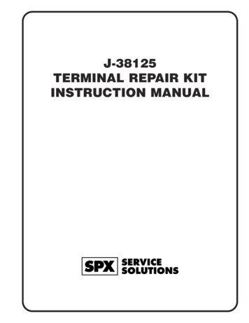
TBO-Quality Crimp Handbook Ferrule CrimpIt is the act of physically compressing (forming) aconnector or contact barrel around a cable in orderto make an electrical connection. On a crimpedterminal, a second crimp is often added to theinsulation area for added strain relief. CSACanadian Standards Association is an independentCanadian testing laboratory similar to UL(Underwriters Laboratories Inc.).A short tube used to mate solderless connectors toshielded or coaxial cable. It is used as an insulationgrip sleeve on solderless terminals. FlashIt is an abnormal protrusion on the wire barrel,(either insulation material or metal), which indicatesthat the crimping tool is either misaligned or wornand thus should not be used. Funnel EntryIt is a crimped terminal or splice barrel, which opensto facilitate quick and easy wire insertion. Cut-off Tab LengthThis material protrudes outside the end of theterminal after the terminal is separated from thecarrier strip. As a rule, the cut-off tab should beflush or .254mm (.010”) protruding outside thehousing sleeve. A cut-off tab, which is too long,may expose a terminal outside the housing or it mayfail electrical spacing requirements. In mostsituations, a tool is setup to provide a cut-off tab thatis flush to one material thickness. Gas Tight SealA contact system that utilizes soft metals at highcontact pressures so that upon mating, metal isupset and the resultant joint prevents contaminantgases from entering the contact area. GaugeA method of measurement, often using “go” and “nogo” pins or shapes to determine whether a device iswithin tolerance. HarnessCARRIER STRIPCUT-OFF TABLENGTH Dielectric TestTests that consist of the application of a voltagehigher than the rated voltage for a specific time forthe purpose of determining the adequacy againstbreakdown of insulation materials and spacing undernormal conditions. This test is used to ensure thecrimping procedure did not puncture or destroy theinsulation material on the terminal. Extrusions (Flash)These small flares form on the bottom wire barrelresulting from the clearance between the punchand anvil tooling. If the anvil is worn or if theterminal is over-crimped an excessive extrusionresults. An uneven extrusion may also result if thepunch and anvil being misaligned.Doc No: TM-640160065Revision: BRelease Date: 00-00-02Revision Date: 10-16-09A group of wires or cables joined to form a circuitnetwork for electronic or electrical equipment. Aharness is usually an assembly of cables cut to theproper length, terminated, and tied together prior tobeing assembled in a piece of equipment. Insulation Crimp (Strain Relief)It is a crimp encompassing both the wire andinsulation. This helps to prevent the conductorfrom being exposed due to the insulation recedingand offers additional resistance to vibration. Insulation Crimp HeightMolex does not specify insulation crimp heightsbecause of the wide variety of insulation thickness,material, and hardness. Most terminals aredesigned to accommodate multiple wire ranges.Within the terminal’s range, an insulation diametermay not completely surround the wire or fullysurround the diameter of the wire. This conditionwill still provide an acceptable insulation crimp formost applications.UNCONTROLLED COPYPage 6 of 27
TBO-Quality Crimp Handbook A large insulation should firmly grip at least88% of the wire. A smaller insulation should firmly grip at least50% of the wire and firmly hold the top of thewire.To evaluate the insulation section, cut the wire flushwith the back of the terminal. Once the optimumsetting for the application is determined, it isimportant to document the insulation crimp height.Then, as part of the setup procedure, the operatorcan check the insulation crimp height. LocatorA device for positioning terminals, splices, orcontacts in crimping dies. MCMEqual one thousand circular mils. Used above 4/0CMA (rather than AWG). MegaPrefix denoting one million, e.g., one Mega volt one million volts. MicroPrefix denotes one millionth, e.g., one Milivolt one thousandth of a volt. Mil SpecMilitary Specification. A specification used forqualification of products for acceptability as requiredfor U.S. Government applications (usually for amilitary branch), e.g. Mil-T-7928 covers terminals,lugs, splices, conductors, crimp style. Mechanical StrengthTo insure how strong the connection is or how muchthe wire and terminal must be squeezed to get a gastight seal. It’s important to crimp the wires tightenough to keep them from slipping out of theconnector, but not so tight as to crush the wires inthe terminal, causing them to break off. Theconnection is weakened if the wires are cut ornicked. NestThe portion of a crimping die, which supports orreshapes the barrel during crimping. PSI(Pounds per Square Inch) Used to denote pressureof air or other gas, e.g. 75 psi. Pull Force TestingPull force testing is a quick, destructive method toevaluate the mechanical properties of a crimptermination. When making a crimp, enoughpressure must be applied to break down the oxidesthat may build up on the stripped conductor and thetin-plating on the inside of the terminal grip. This isnecessary to provide a good metal-to-metal contact.If this does not occur, resistance can increase.Over-crimping a crimp termination will reduce thecircular area of the conductor and increaseresistance.Pull force testing is also agood indicator of problemsin the process. Cut ornicked strands in thestripping operation, lack ofbell mouth or conductorbrush, or incorrect crimpheight or tooling will reducepull force. Wire propertiesand stranding, and terminaldesign (material thicknessand serration design), alsocan increase or decrease pull force levels. SerrationsIt is the saw-toothed grooves on the surface of aterminal, which ensures firm gripping of theconductor. Also provides additional contact area. SolderlessThis means without solder – in our case, denotingthe use of a crimping tool. SpliceA device used to join two or more conductorstogether.Doc No: TM-640160065Revision: BRelease Date: 00-00-02Revision Date: 10-16-09UNCONTROLLED COPYPage 7 of 27
TBO-Quality Crimp Handbookdetermines conductor, cut-off tab length, andterminal extrusions. Strip LengthThe strip length is determined by measuring theexposed conductor strands after the insulation isremoved. The strip length determines theconductor brush length when the insulation positionis centered.PUNCHESTERMINALWIRE*Consult individual terminal specificationrequirementsSTRIPLENGTHANVILS ULUnderwriters’ Laboratories, Inc., founded in 1894,is chartered as a not-for-profit organization underthe laws of Delaware, to establish, maintain, andoperate laboratories for the investigation ofmaterials, devices, products, equipment,construction methods, and systems with respect tohazards affecting life and property. TabFlat rectangular male connection tabs on electricalcomponents; various sizes to fit female quickdisconnects. Tensile TestThis is a pull test to determine the mechanicalstrength of the crimped wire. They are specificminimum values set for each wire size. See Section8. TerminalA device designed to terminate a conductor that is tobe affixed to a wire or cable to establish an electricalconnection. It is a synonym for contact. There aretwo main types, which include the open barrel andthe closed barrel. Parts of the terminal are:Insulation barrel Where the wire’s insulation will becrimped or supported so that it isfirmly gripped.Wire barrelWhere the bare wire will becrimped.Contact area Where the terminal will be attachedto the mating part. Voltage Drop TestA test of the voltage developed across a componentor conductor by the current in the resistance orimpedance of the component or conductor. It is thetest of the electrical integrity of the crimp. WireThey are a group of conductors that has a lowresistance to current flow, together with anyassociated insulation. There are two kinds: a solidwire, which is one single strand of material, orstranded group of wire, which is a bundle of wirestwisted together to act as one. Wire SizeWires have varying sizes or gauges that carrydifferent amounts of electrical current with each wireused for a separate purpose. The size is called outwith a number, such as 8 or 10, followed by theletters AWG, which stand for American Wire Gauge. Terminal PositionThe terminal position is set by the alignment of theterminal to the forming punch and anvils, and thecarrier-strip cut-off tooling. The tool set-upDoc No: TM-640160065Revision: BRelease Date: 00-00-02Revision Date: 10-16-09UNCONTROLLED COPYPage 8 of 27
TBO-Quality Crimp Handbook Wire StopIt is a stop at the end of a terminal wire barrel. Itprevents wire from passing completely through thebarrel so the wire will not interfere with the functionof the contact.WIRESWIRE STOPDoc No: TM-640160065Revision: BRelease Date: 00-00-02Revision Date: 10-16-09UNCONTROLLED COPYPage 9 of 27
TBO-Quality Crimp HandbookSECTION 4ASSOCIATED MATERIALS CaliperIt is a gauge, consisting of two opposing blades, formeasuring linear dimensional attributes. Pull Tester Eye LoopIt is a magnification tool,normally 10 times power orgreater, which is used to aidvisual evaluation of a crimptermination.A device used to determine the mechanical strengthof a crimp termination. Most pull testing is donewith a device that clampsthe wire, pulls at a setspeed, and measures forceby means of a load cell. Apull tester also can be assimple as hanging fixedweights on the wire for aminimum of one minute. Toolmaker’s MicroscopeThis is used for closevisual evaluation andstatistical measurement of bell mouth, cut-off tab,conductor brush, wire position, and strip length. Crimp MicrometerThis is a micrometerspecifically designed tomeasure crimp height. Themeasurement is taken in thecenter of the crimp so theconductor bell mouth doesnot influence it. It has a thinblade that supports the top ofthe crimp while a pointedsection determines thebottom radial surface. Ruler (Pocket Scale)This is used to estimate the five-piecemeasurement of bell mouth, cut-off tab, conductorbrush, wire position, and strip length. Therecommended maximum resolution is 0.50mm(.020”).Doc No: TM-640160065Revision: BRelease Date: 00-00-02Revision Date: 10-16-09UNCONTROLLED COPYPage 10 of 27
TBO-Quality Crimp HandbookSECTION 55.1 Features of Solderless TerminalsThe quality of the base material must be evaluated. The material (metal) is either copper or brass depending on theproduct. Molex base metals are purchased, inspected, and received to Military specifications. Most of these terminals use the guidelines of UL; Underwriters Laboratories is a US organization that sets certainstandards for connector testing. Some terminals use the guidelines of Mil-T-7928, set by the United States Government.The following charts show the UL and US Government specifications (MIL-T-7928) for various wire sizes. Thetensile strength is shown in pounds. It indicates the minimum acceptable force to break or separate the terminalfrom the conductor.Color Code Wire Size (AWG) *UL - 486 A *UL – 486 C *UL – 310 *Military Class 610050N/A300*UL - 486 A - Terminals (Copper conductors only)*UL - 486 C - Butt Splices, Parallel Splices, Closed End Connectors, and Wire Nuts*UL - 310 - Quick Disconnects, Flag and Couplers*Military Class 2- Military Approved Terminals only as listed5.2 Barrel Serration/Dimples1. When quality solderless terminals are stamped, the inside of the barrel isscored with serrations or dimples.2. When the crimp is made and the metal terminal barrel is drastically deformed,the tin plating on the inside of the barrel is fractured at the serrations, thuscausing bare copper-to-copper contact between the wire and the terminalbarrel. This greatly enhances electrical conductivity.3. If properly designed, the serrations, or dimples, have angled grooves that,during the crimping operation, will bite into the wire, which will greatly increasethe mechanical integrity of the crimp.4. A quality solderless terminal has features built into the barrel that insures aquality crimp.5. The non-insulated terminal will have a chamfer at the wire insertion end so theindividual strands will not bump against the end of the metal.6. An insulated terminal, the insulation should have a funnel entry. This acts as aslide for the wires to enter the barrel smoothly.7. There are two styles of insulated barrels. Both have a funnel feature.Doc No: TM-640160065Revision: BRelease Date: 00-00-02Revision Date: 10-16-09Plain InsulationPlastic InsulationSleeveTerminalFunnel EntryInsulation withSupport SleeveTin-PlatedBrass SleeveUNCONTROLLED COPYNylon SleevePage 11 of 27
TBO-Quality Crimp Handbook5.3 Barrel StylesThe barrel is the part of the terminal that is crimpedaround the wire. Molex offers different styles listedbelow.1. The Krimptite is the basic Molex barrel style. It isnon-insulated and is a oneTONGUE (STYLE VARIES)piece design. ThisSEAMterminal is the mosteconomical and has thegreatest variety of useswhere special features arenot required. It is availableTRANSITIONin 10 to 26 AWG (0.10 toBARREL OR THROAT6.60mm2). KRIMPTITE2. The Versakrimp is the same as the Krimptite ,except the seam is brazed (welded) closed. Thisbrazed-seam barrel terminal will not open underconditions of stress or wire pull. This allows forcrimping from any direction without the barrelopening up, andTONGUE (STYLE VARIES)provides greaterNO SEAMtensile strength. Thisterminal is ideal forhard to crimp solid andstranded wires. It isTRANSITIONavailable in wire rangeOR THROATBARREL4/0 to 22 AWG (0.10 toVERSAKRIMP 117.00mm2).3. The Insulkrimp has a rigid insulation sleeve madeof PVC (polyvinyl chloride), which protection to theKrimptite barrel area in wire sizes of 10-22 AWG orthe brazed seam of the Versakrimp barrel of 4/0 to22 AWG. It is available in wire range 4/0 to 22AWG (0.10 to 117.00mm2).4. The Avikrimp has a color-coded sleeve, whichprovides insulation as well as an insulation grip.The insulation is made of Nylon, and has asecondary tin-plated brass sleeve added. Thisbrass support sleeve is crimped around the wireinsulation providing a strain relief, so the wire doesnot vibrate,TIN-PLATEBRASS SLEEVEloosen, fray, orbreak. It isavailable in 10to 26 AWGNYLON SLEEVE(0.10 to26.60mm ).AVIKRIMP 5. The Open Barrel product is used in manufacturingoperations where quantity of work is needed. Theopen barrel allows the wire to be crimped faster andeasier and is the barrel style preferred when usingautomated wire processing equipment.INSULATIONSUPPORTCARRIERSTRIPOPEN BARRELSTRIPQUICKDISCONNECTSAND RINGTERMINALS6. The Nylakrimp is specifically designed for largewire applications. The color-coded barrel is affixwith a permanent rigid color-coded nylon insulatedsleeve. It has a funnel entrance that eliminates wirestrand fold back. It is available in wire range 4/0 to 8AWG (8.50 to 117.00mm2).NYLON SLEEVEBARRELHEAVY MP INSULKRIMP Doc No: TM-640160065Revision: BRelease Date: 00-00-02Revision Date: 10-16-09UNCONTROLLED COPYPage 12 of 27
TBO-Quality Crimp Handbook7. The Perma-Seal is specifically designed for waterresistant applications. The color-coded barrel has apermanent rigid color-coded nylon insulated sleeve.It has a funnel entrance that eliminates wire strandfold back. It is available in wire range 10 to 22 AWGNYLON SHRINK(0.10 to 6.60 mm2).TUBING8. The Eyelet can beused in place ofPERMA-SEAL standard compressionterminals because itSEAMLESS BARRELis deep drawn fromCDA-110electrolytic pitchcopper and then tin- EYELETplated for corrosionresistance. It has aFLARED BARRELseamless barrelENTRYwith a flared barrelentry. It is available in wire range 8 to 500 MCM. Tongue StylesThe “Tongue” is the end of the terminal that attachesto other components (switch, stud, transformer, etc.).These tongue configurations vary. The following aresome examples:RINGSSPADESSNAP SPADESDoc No: TM-640160065Revision: BHOOKSFLANGEDSPADESFLAG RINGSRelease Date: 00-00-02Revision Date: 10-16-09MULTI STUDSFEMALE QUICKDISCONNECTSSTAR RINGSMALE QUICKDISCONNECTS Barrel LengthsIn wire sizes 26-16 AWG, the industry has twostandard barrel lengthsfor the metal barrel.The lengths are 6.35BARRELmm (.25”) and 4.36 mmLENGTH(11/64”). The 4.36 mmbarrel is the OEM(Original Equipment Manufacturer) standard barrellength. The 6.35 mm barrel is more commonly usedin the maintenance and aftermarket segments ofindustry.The purpose of the longer barrel is simply to give theuser a bigger target area to crimp. These barrellengths are not so important if you use a terminalwith the molded step construction on the insulation,or if a precision ratchet tool with terminal locator isused. OEM tooling is usually designed for only shortbarrel terminals. Step Construction Insulation for Tool LocationThe “step” on the insulation of molded terminals isused to position (locate) the crimping tool. The toolshould rest on the step and crimp made just aboveit. This insures that the entire width of the crimpingtool is hitting on the barrel below. This stepconstruction is very important when using a nonratchet maintenance tool without a locator.UNCONTROLLED COPYPage 13 of 27
TBO-Quality Crimp Handbook Step Down Butt SlicesLOCATETOOL HERESTEPCONSTRUCTION Insulation Barrel ColorsThe colors on the insulation barrel (red, blue, andyellow) are used to indicate the wire range. Thecolors repeat themselves and are an industrystandard color-coding. See the Chart below.Color Code Wire Range ue6Yellow4There are different kinds of barrels with differentshades of the same color, which are used fordifferent barrel styles. PVC and Nylon take the colordifferently. In the 14-16 AWG range (blue) forexample, the PVC barrels will be dark blue. Thenylon barrels will be a lighter, translucent blue.When using the lighter blue terminals, the secondarysleeve will be crimped in addition to the wire barrelcrimp. The actual shade of color has nothing to dowith quality of the insulation. Avikrimp Butt SpliceWith the extra metal sleeve and nylon insulation,these splices should be used when heavy vibrationis anticipated and astrong strain relief isneeded. Nylon Closed –End ConnectorUsed in a wide variety ofsituations to “pigtail” or tietogether two or more wires. Funnel Entry Butt SpliceIn the past, the crimping of machine terminated buttsplices has been difficult and nearly impossible ifattempted on a piece of robotic equipment. Now,with our new Funnel Entry Butt Splice, the end thatwill be crimped by the crimping press is funneled toallow quick and easywire insertion. Perma-Seal Splices 5.4 SplicesMolex-offers standard and special splices for nearlyevery type of wiring need. Butt SlicesOn this connector, thestripped wires areinserted from each endand they "butt" in thecenter. Then a crimp ateach end secures theconnection.Doc No: TM-640160065Revision: BThe Step Down Butt Splice is the perfect solutionwhen two wires needto be inserted in oneend of a splice and asingle wire in theother end.Release Date: 00-00-02Revision Date: 10-16-09The tough sleeve of Perma-Seal splices resistabrasion and cutting. This protective helps tomaintain the insulation and sealing properties evenin hostileenvironments, notto mentionunbeatable strainrelief.UNCONTROLLED COPYPage 14 of 27
TBO-Quality Crimp Handbook Wire Tap Parallel SpliceThe Wire Tap makes tapping into an existing wirequick, easy, and reliable. This Tap-and-Run spliceis actually a fully insulated female quick disconnectthat can be spliced onto a wire and then mated witha .250 x .032 fully insulated, partially insulated, ornon-insulated male quick disconnect all withoutstripping, twisting, soldering, or the need for specialtools. The Wire Tap is actually a female quickdisconnect. Multi-LockThese color-coded connectors make quick, reliable,and pre-insulated splices without stripping, twisting,soldering, or the need forspecial tools.Doc No: TM-640160065Revision: BRelease Date: 00-00-02Revision Date: 10-16-09This connector has stripped wires that lie side-byside in the splice. They are secured by a singlecrimp in themiddle. Window ButtSpliceThis connector has military approval (Mil-T-7928/5)to withstand the harshest environments. Thewindow guarantees proper wire insertion and crimptool alignment. They are nylon insulated and havean insulation grip that provides superior strain relief.UNCONTROLLED COPYPage 15 of 27
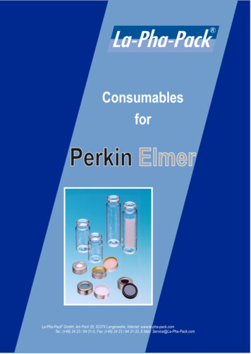
TBO-Quality Crimp HandbookSECTION 6REJECTImproper Stripping“Nicked” StrandsACCEPTPROCEDURES6.1 Preparing the WireCheck the stranded wire to see if any strands haveloosened and expanded to be larger than the wire andthe insulation together. If this has occurred, twist thewires to the size they were before they were stripped. Besure that the stranded wire is within the outside diameterof the insulation after you have twisted them.REJECTExpanded StrandsACCEPTLoose WireWire withinOutside DiameterExceedsOutside DiameterCheck the insulation to ensure that ther
Circular Mil Area (CMA) A unit of area used to indicate wire size. It is the computed total cross sectional area of conductors. One circular mil equals cross-sectional area of a wire one mil (0.001 inches) in diameter. Contact Area It is the area in contact between two conductors, or a conductor and a connector permitting the flow of electricity.