Transcription
Roadway Lighting DesignCourse No: C02-061Credit: 2 PDHDebra Kennaugh, P.E.Continuing Education and Development, Inc.22 Stonewall CourtWoodcliff Lake, NJ 07677P: (877) 322-5800info@cedengineering.com
Roadway Lighting DesignDebra A. Kennaugh, P.E.
I.IntroductionA. Objectives of Roadway LightingB. Visibility RequirementsII.Analyzing Lighting NeedsIII.Lighting EquipmentA. Light SourcesB. LuminairesC. Luminaire SupportsD. Bracket Arm TypesIV.Conventional LightingV.Highmast LightingVI.Sign LightingVII.Underdeck LightingVIII. Mounting Height RestrictionsIX.Lighting Project CoordinationX.Maintenance of Existing Lighting During ConstructionXI.Voltage Drop CriteriaXII.Grounding
XIII. Designing the Lighting SystemA.B.C.D.E.F.G.H.I.J.Design ConceptsDesign CriteriaLighting TerminologyGlareSpacing ArrangementsIES Light DistributionsTypes of CutoffsTypes of DistributionsPhotometric DataBasic Lighting EquationsXIV. Summary
I. IntroductionThe general purpose of roadway lighting is to provide improved visibility for the various users ofthe roadways and associated facilities.“Users” refer to vehicle operators (automobiles, trucks, buses, motorcycles, bicycles),pedestrians and other citizens such as merchants and shoppers.“Associated Facilities” refer to physical features along the roadway (barriers, bridge piers,ditches, curbs, channelization, etc.).Roadway lighting on local streets provides pedestrian visibility as well as driver visibility.Lighting quality increases the comfort level and safety of the motorist. Lighting can be expectedto reduce night crashes by approximately 30 percent.A. Objectives of Roadway Lighting To supplement vehicle headlights, extending the visibility range beyond their limitsboth laterally and longitudinally. To improve the visibility of roadway features and objects on or near the roadway. To delineate the roadway ahead and improve visibility of the surroundings. To reduce the apprehension of those using the roadway.B. Visibility RequirementsVision – The eyes are the primary source of information. As light decreases, vision and thedetection of information are severally impaired or nonexistent. As light increases, vision and thedetection of information are improved.Contrast is the difference in brightness between the object and background. The ability todiscern objects increases as the contrast level between the two increases. Drivers normally seeobjects in silhouette – a dark area against a bright background. This bright background can
cause a glare resulting in a reduction in the contrast level thereby partially or totally obscuringthe details to be seen.II. Analyzing Lighting NeedsThe warrants for roadway lighting are located in AASHTO’s “An Informational Guide forRoadway Lighting”. The manual contains a basic guide for highway lighting and containsdesign guidelines and warranting criteria.A lighting justification analysis was created due to the energy crisis of the 1970’s and based onrecommendations of a research project; a lighting justification program was developed. It isused to calculate the cost benefit analysis of lighting. The FDOT Office of Traffic Operations inTallahassee may be contacted for a copy of the program.III. Lighting EquipmentA. Light SourcesThere are three general types of light sources: LED, filament and arc-discharge.Light SourceTypeLumensLife (hrs)LEDLED2-9050,000Filament LampIncandescent10-1512,000Discharge LampFluorescent60-707,500-24,000Mercury Vapor50-6524,000Metal Halide90-11010,000-20,000High Pressure Sodium125-14024,000Low Pressure Sodium18018,000LED (Light-Emitting Diode)An LED roadway light is an integrated light that uses light emitting diodes (LED) as its lightsource. These are considered integrated because the luminaire and fixture are not separate parts.Most LED roadway lights have a lens on the LED panel, which is designed to cast its light in arectangular pattern aiming the majority of the light to the street side. The primary appeal of LED
roadway lighting is energy efficiency compared to conventional roadway lighting fixturetechnologies. An LED fixture uses considerable less electricity than the traditional light fixtures.In addition, an LED fixture will have a longer life than the traditional light fixtures. This resultsin a reduction in maintenance cost. A disadvantage of LED lighting is increased glare.Incandescent LampThe incandescent lamp has a filament that is an electrical resistance wire enclosed in a gas filledbulb. Current passing through the filament heating the filament to incandescence produces light.The gases are inert, usually nitrogen or krypton, which reduce evaporation of the filament andact as a thermal barrier.Discharge LampThe discharge lamp produces light by exciting gases or metal vapors in a lamp or tube.Electrical potential is applied to electrodes. Gas is ionized and current flows between theelectrodes. The lamps have a negative resistance and must have a ballast to maintain propercurrent level. The ballast regulates input power for the lamp.Fluorescent Lamp - The fluorescent lamp produces light by a fluorescent coating on the inside ofthe tube which is activated by an ultraviolet energy generated by an arc.Mercury Vapor - The mercury vapor lamp consists of an arc tube inside the outer bulb containingmercury vapor and electrodes. Light is produced from ionization of mercury vapor. Lamps maybe clear or coated with phosphors to improve color rendition.Metal Halide - Metal halide light is produced by a combination of metallic vapors. The lamp hasexcellent color rendition, but has a short lamp life.High Pressure Sodium - The high pressure sodium lamp produces light from sodium vapor. Thearc tube is normally filled with sodium, mercury and xenon. Xenon is used for starting the lightand mercury for coloring. This lamp has no starting electrode and produces a high voltage pulseof 2,500 to 4,000 volts.
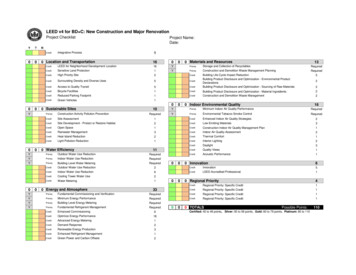
Low Pressure Sodium - The low pressure sodium lamp is very efficient. However, it ismonochromatic (single color only). It has a large physical size and the light is hard to control. Italso has a lower lamp life.B. LuminariesThe luminaire components consist of a housing of the ballast and optical assembly. The opticalassembly components consist of the lamp, reflector and refractor. The lamp produces the lightoutput for the luminaire. The reflector is mounted above the lamp inside the optical assembly. Itreflects or redirects the light. The refractor is mounted below the lamp and in some luminariesencloses the lamp cavity. The refractor is made of a transparent, clear material, glass or a strongplastic material. It has a large number of prisms and is enclosed or open at the bottom.The following illustration shows the components of a typical luminaire.C. Luminaire SupportsLuminaire supports generally have frangible/breakaway bases. The breakaway criteria arecovered in the AASHTO Specifications. The term “breakaway support” refers to all types ofsign, luminaire and traffic signal supports that are design to yield when hit by a vehicle. Therelease mechanism may be a slip plane, plastic hinges, fracture elements, or a combination ofthese. Frangible/breakaway bases are safer in vehicular collisions since the light base will yieldin the collision.
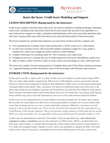
The standard pole is made of aluminum. However, in some locations they may be concrete orfiberglass. Joint use poles may combine the luminaire with signals or utilities on wood, concrete,or steel poles. All conventional height poles shall be breakaway unless bridge or barrier wallmounted. High mast poles are made of steel or concrete. These structures must be installedoutside of the clear zone as they are not frangible/breakaway.FDOT has developed an aluminum light pole standard for Conventional Lighting foundations.The standard provides details for 40, 45 and 50-foot luminaire mounting heights on polesmounted either at grade or on fills up to 25 feet in height, all of which accommodate fixture armlengths of 8, 10, 12 and 15 feet. Standard Aluminum Light Poles have been designed for 110,130, and 150 mph design wind speeds. High mast lighting (80 feet or greater) requires afoundation design in the plans.D. Bracket Arm TypesBracket arm types may consist of single member, truss, or davit. The length and rise may vary.The length is determined in the design of the lighting system and is measured to the center of theluminaire. The rise is the difference in elevation between the attachment at the pole andconnection to the luminaire. The contractor usually calculates the rise because it depends on thelength of the pole and mounting height required.Single MemberBracket ArmTruss Bracket Arm
Davit Bracket ArmIV. Conventional LightingConventional lighting consists of any number of mounting heights depending upon the desiredlighting level. The standard FDOT mounting heights are 40, 45, and 50 feet. There is oneluminaire per pole for conventional mountings. There can be two luminaries per pole if it ismedian mounted. The following table outlines the FDOT requirements for illumination levelsand uniformity ratios for conventional lighting.Table 7.3.1 Conventional Lighting – Roadways (FDOT PPM, Chapter 7)RoadwayClassificationsIllumination LevelAverage InitialHorizontal FootCandle (H.F.C.)Uniformity RatiosAvg./Min.Max./Min.Interstate,Expressway, Freeway& Major Arterials1.54:1 or less10:1 or lessAll Other Roadways1.04:1 or less10:1 or less* Pedestrian Waysand Bicycle Lanes2.54:1 or less10:1 or lessV. Highmast LightingHigh mast lighting consists of a mounting height of 80 feet or greater. The standard mountingheight is 120 feet. There are several luminaries per pole. The number of luminaries depends onthe light level required. The maximum number of luminaries per pole is 12 highmast or 16flood. The luminaries are attached to a ring by cables and to a winch inside the pole base. The
ring and luminaries lower to the ground by the winch for maintenance. Either a heavy duty drillmotor attaches to the pole to operate the winch or a previously installed electric motor lowers thering. The following table outlines the FDOT requirements for illumination levels and uniformityratios for high mast lighting.Table 7.3.2 Highmast Lighting – Roadways (FDOT PPM, Volume 1, Chapter 7)Illumination LevelAverage Initial(H.F.C.)Avg./Min.Max./Min.Interstate, Expressway,Freeway, & Major Arterials0.8 to 1.03:1 or less10:1 or lessAll Other Roadways0.8 to 1.03:1 or less10:1 or lessRoadway ClassificationsUniformity RatiosThe following illustrations shows high mast lighting at an interchange.The following illustration shows a highmast light being lowered for light maintenance.
VI. Sign LightingOverhead sign structures require overhead sign lighting so the messages are visible during theday and night. The following table outlines the FDOT requirements for illumination levels anduniformity ratios for sign lighting.Table 7.3.3 Sign Lighting (FDOT PPM, Volume 1, Chapter 7)Ambient LuminanceIllumination Level AverageInitial (H.F.C.)Uniformity RatiosLow15-206:1Medium & High25-356:1Max./Min.In recent years, sign manufacturers have developed a special sheeting on the sign that usesvehicle headlights to illuminate the sign. The cost of these signs is greater than the cost ofconventional signs. However, the use of this type of sheeting reduces the cost of sign lightingand the associated conduit and pull boxes.VII. Underdeck LightingMany of the major interchanges today have numerous wide overpasses. In these locations,lighting is required for the roadways underneath the overpasses for both day and night visibility.Underdeck lighting is accomplished by mounting either pier cap or pendant hung fixtures underthe bridge structure. Pier cap luminaries should be installed when bridge piers are located lessthat 15 feet from edge of travel lane. Pendant hung luminaries shall be mounted to the bottom ofthe bridge deck and should be suspended where 50% of the lamp is below the bridge beam.Under no circumstances shall any luminaire or conduit be allowed to attach onto the bridgegirders. The light levels for underdeck lighting shall be equal to the adjacent roadway lighting.The following table outlines the FDOT requirements for the light source and mounting locationfor underdeck lighting.Table 7.3.4 Underdeck Lighting – Roadways (FDOT PPM Volume 1, Chapter 7)Luminaire TypeLight Source(High Pressure Sodium)Mounting LocationPier Cap150 watt to 250 watt HPSPier or Pier CapPendant Hung150 watt to 250 watt HPSBridge Deck
The following illustration shows a commonly used pendant light for underdeck lighting.VIII. Mounting Height RestrictionsFDOT has established a minimum mounting height for high pressure sodium (HPS) luminairesof various wattages. The following table shows the minimum mounting heights per luminairewattage.Table 7.3.6 Mounting Height Restrictions (FDOT PPM Volume 1, Chapter 7)Luminaire WattageLight SourceMounting Height(Min.) (Feet)150High Pressure Sodium (HPS)25200High Pressure Sodium (HPS)30250High Pressure Sodium (HPS)30400High Pressure Sodium (HPS)40750High Pressure Sodium (HPS)501000High Pressure Sodium (HPS)80
IX. Lighting Project CoordinationCoordination with other offices and other agencies is a very important aspect of project design.It is important that the lighting designer coordinates with roadway design, utilities, drainage, andstructures. The roadway designer provides the base sheets and cross sections for the lightingDesign to be used in the coordination. The utilities engineer provides the coordination between the lighting designer and theutilities involved in the project. The utilities engineer can also identify potentialconflicts with overhead and underground utilities. The drainage designer should check the locations of highmast poles to determine ifhigh water level is a problem. Highmast poles are often located in the center ofinterchange loops that may be the same areas used as drainage retention areas. The structural engineer should be contacted early in the design phase to allow adequatetime for coordination. While conventional height pole foundations are covered in theFDOT Design Standards and FDOT Standard Specifications, highmast poles require afoundation design. In addition, soil borings are required for this design.X. Maintenance of Existing Lighting During ConstructionThe maintenance of existing lighting shall be the responsibility of the contractor only if thelighting is affected by the construction. The contractor should not be expected to replace lampsand pole knockdowns or to repair wiring if these problems are not caused by the constructionwork. The plans should specify the scope of the contractor’s responsibility for the maintenanceof existing lighting.XI. Voltage Drop CriteriaWhen determining conductor sizes for lighting circuits, the maximum allowable voltage dropfrom the service point on any one circuit is 7%.XII. GroundingThe grounding requirements for lighting systems shall be as follows:
Install 20’ of ground rod at each conventional height light pole and at each pull box. Install 40’ of ground rod at each electrical service point. At each highmast pole, install an array of 6 ground rods 20’ in length, as shown inthe Design Standards, Index 17502.XIII. Designing the Lighting SystemA. Design ConceptsThere are two concepts or techniques for the design of highway lighting allowed by theAASHTO guide for lighting.The Illumination Concept is the measure of light striking a surface. Illumination is the designmethod adopted by the FDOT and most agencies in the United States.The Luminance Concept (brightness) is the measure of light reflected from a surface.Luminance requires a more complex design process and knowledge of the reflectivecharacteristics of the pavement surface used. These reflective characteristics change as thepavement ages and with variations in weather conditions.There are numerous off-the-shelf computer programs to assist the engineer with lighting design.These programs use the information from the proposed luminaire along with the layout inputfrom the engineer to determine if the fixture layout meets criteria.B. Design CriteriaThe designer responsible for a highway lighting project should be aware that the design mustcomply with various standards. The design criteria for highway lighting are in the FDOTRoadway Plans Preparation Manual, Volume 1, Chapter 7, FDOT Standard Specifications,FDOT Design Standards, AASHTO Roadway Lighting Design Guide and AASHTO StandardSpecifications for Structural Supports for Highway Signs, Luminaires and Traffic Signals, andFDOT Structures Manual.
C. Lighting TerminologyIt is important in the design of a lighting system that all of the appropriate terminology isunderstood to ensure the proper design.Arm length is the distance from the support to the middle of the luminaire.Coefficient of utilization is the percent of luminaire output. It is the amount of light that falls ona selected area of roadway.House side is the side of the luminaire casting light away from the roadway.Mounting height is the vertical distance from the roadway the light source.Overhang is the distance between the edge of pavement to the center of the luminaire.Pole setback is the horizontal distance from the edge of the travel lane to the pole.Nadir is that point of the celestial sphere directly opposite to the zenith and directly below theobserver. It is the lowest point.Roadway width is the width of the roadway used in the lighting calculations for the luminaire tolight.Street side is the side of the luminaire casting light towards the roadway.Zenith is the point in the sky directly overhead; that point of the celestial sphere directly oppositeto the nadir. It is the highest point.D. GlareGlare is an unusual sensation caused by excessive and uncontrolled brightness. It can bedisabling or simply uncomfortable. Disability glare is the reduction in visibility caused byoverly bright light sources.
It is important that the lighting designer keep glare in mind in the design process. A design withfewer light fixtures at a higher wattage may result in the required luminance. However, thehigher wattage may result in a situation with glare. Therefore, a design with more light fixturesat a lower wattage would be preferable because it would reduce the glare.The illustration below shows a street with disability glare caused by using fewer light fixtureswith higher wattages.The illustration below shows roadway lighting without glare with the use of more fixtures withlower wattages.
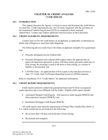
E. Spacing ArrangementsSpacing arrangements consist of one side, staggered, opposite, median mounted and overhead.The lighting designer determines the spacing arrangement. The most common spacingarrangement is staggered. Some spacing arrangements may not provide proper light levels. Forexample, on a divided roadway with a median barrier, consider a median mounting. Anillustration of the varying spacing arrangements is shown below.(a) One Side Arrangement(b) Staggered Arrangement(c) Opposite Arrangement(d) Median Arrangement(e) Overhead ArrangementOne side arrangement is generally used on minor streets with two lanes. This is because if itwas used on a wide street, there would be areas of the roadway that were darker than others. Theuniformity ratios would not be acceptable.Staggered and opposite arrangements are generally used on multi-lane facilities. This is becausethey provide a good distribution of light resulting in acceptable uniformity ratios.Median arrangements are generally used on multi-lane facilities that have limited right-of-wayon the outside of the roadway. By placing the lights in the median, good uniformity ratios can beobtained in limited right-of-way conditions.
Overhead arrangements are rarely used. This is because a structural system has to be designedto hold the light fixtures. The other types of arrangements have the structural supports alreadydesigned by the light manufacturer. The overhead arrangement would result in higher designand construction costs.F. IES Light DistributionsIES light distributions are based on vertical light distribution, lateral light distribution, andcontrol of light distribution above maximum candlepower.Vertical Light DistributionShort distribution – The maximum candlepower beam strikes the roadway surface between 1.0and 2.25 mounting heights from the luminaire. This type of distribution should be used in areaswhere vertical light distribution is an issue such as near airports.Medium distribution – The maximum candlepower beam strikes the roadway surface at somepoint between 2.25 and 3.75 mounting heights from the luminaire.Long distribution – The maximum candlepower beam strikes the roadway surface at some pointbetween 3.75 and 6.0 mounting heights from the luminaire. This type of distribution should notbe used in areas where vertical light distribution is a concern such as near airports.G. Types of CutoffsControl above maximum candlepower affects the glare from a luminaire. The following are thetypes of luminaries that are available for use.Full Cutoff - When the candlepower per 1,000 bare lamp lumens does not exceed 25 at an angleof 90 degrees above nadir; and 100 at an angle of 80 degrees above nadir. This type of luminairewould be used in an interstate corridor passing through a neighborhood because it would controlthe spill over light and reduce glare.Semi-cutoff – When the candlepower per 1,000 bare lamp lumens does not exceed 50 at an angleof 90 degrees above nadir; and 200 at an angle of 80 degrees above nadir.
Non-cutoff – When there is no candlepower limitation in the zone above maximum candlepower.This luminaire would be used in a high mast condition where spill over light is not a concernsuch as undeveloped interchanges.H. Types of DistributionThere are five different lateral distribution patterns to choose from when designing a lightinglayout. They consist of Types I, II, III, IV and V. An illustration of the different distributionpatterns is shown below. Type I is considered a full cutoff fixture. It is the most restrictive pattern of lighting. Itconcentrates the majority of the light on the roadway. There is minimal spill over light to thehouse side of the luminaire. This pattern of lighting is ideal for roadways within residentialareas. Type II is considered a cutoff fixture. It is a restrictive pattern of lighting. It is slightly lessrestrictive than Type I. It also concentrates the majority of the light on the roadway. There isminimal spill over light to the house side of the luminaire. This pattern of lighting is ideal forroadways within residential areas. Type III is considered a semi-cutoff fixture. It is a less restrictive pattern of lighting than TypeII. However, Type III provides light for a wider section of roadway. Type IV is considered a semi-cutoff fixture. It is a less restrictive pattern of lighting thanType III. However, Type IV provides light for a wider section of roadway.
Type V is considered a non-cutoff fixture. It has a high mast lighting pattern. The light isequally distributed in a circle surrounding the luminaries. This pattern of lighting is notsuitable for residential areas.Depending on the lighting design, the luminaire can be set in the following methods: On the Roadway Edge Offset OverhangGenerally, overhang fixtures will provide the most amount of street side lighting whileminimizing house side lighting. However, these fixtures are often more difficult to maintainbecause the luminaire is located over the lane of traffic.Fixtures on the roadway edge and offset will provide less street side lighting and more house sidelighting than the overhang fixture. However, maintenance is easier because the luminaire is notlocated over the travel lane.The following illustration shows an overhang luminaire.The following illustration shows an overhang luminaire spilling light to the street and housesides. Roadway lighting that spills over to the house side is also known as light trespass.
I. Photometric DataThe luminaire manufacturers have photometric data sheets for each type of lamp. These datasheets contain valuable information for the lighting designer. It contains the luminaire name andreflector and refractor numbers. Also included are lamp wattage and type of cutoff. Thisinformation is used to create a simulation of a utilization curve and isofootcandle curves. Thesetables show the difference in the amount of light distributed to the street side and house side ofthe luminaire. This information assists the designer in determining if the proper cutoff fixture isbeing used for the specific application.J. Basic Lighting EquationsThe following equations can be used to calculate roadway lighting spacing.SP (LL x CU x MF) / (FC x W)(English): SP (LL x CU) / (FC x W), where FC Footcandles Lumens/Square Foot(Metric): SP (LL x CU) / (LUX x W), where Lux Lumens/ Square Meter
Abbreviations:FC FootcandlesLUX Light level on the roadwayLL Lamp LumensCU Coefficient of UtilizationMF Maintenance FactorW Roadway WidthSP SpacingSummaryObjectives for roadway lighting were provided. Lighting equipment was listed and defined.Luminaire components, luminaire supports and bracket arms were discussed.Conventional, high mast, sign and underdeck lighting requirements were identified.Design criteria for roadway lighting was discussed. Lighting terminology was defined.Different spacing arrangements were shown.IES lighting distribution and types of light cutoffs were discussed.Finally, basic lighting equations were provided.This course should assist an engineer in the planning and design of roadway lighting plans.
The warrants for roadway lighting are located in AASHTO’s “An Informational Guide for Roadway Lighting”. The manual contains a basic guide for highway lighting and contains design guidelines and warranting criteria. A lighting justification analysis was cr