Transcription
MODEL 6300-M4 Rev. A3USER'S MANUALLAVERSAB INC.,505 GILLINGHAM LANESUGAR LAND TX 77478(281) 325-8300FAX: (281) 325-8399Email: aservice@laversab.comDocument Number: 9043 REV A3Date: February 23, 2011.
WARRANTYLaversab Inc., warrants its products to conform to or exceed the specifications asset forth in its catalogs in use at the time of sale and reserves the right, at its owndiscretion, without notice and without making similar changes in articles previouslymanufactured, to make changes in materials, designs, finish, or specifications. LaversabInc. warrants products of its own factory against defects of material or workmanship for aperiod of one year from date of sale.Liability of Laversab Inc. under this warranty shall be limited to replacing, free ofcharge (FOB Houston, Texas), any such parts proving defective within the period of thiswarranty, but Laversab Inc. will not be responsible for transportation charges,consequential or incidental damages. No liability is assumed by Laversab for damagesthat are caused by misuse or abuse of the product.The warranty of Laversab Inc. is not made for products manufactured by otherswhich are illustrated and described in Laversab catalogs or incorporated in Laversabproducts in essentially the same form as supplied by the original manufacturer.Warranties of the original manufacturers supplant the warranty of Laversab Inc., but, inapplicable instances, the latter agrees to use its best efforts to have original suppliers makegood their warranties.i
COPYRIGHT NOTICECopyright (c) 2010 by Laversab Inc. All rights reserved. The content of this manual maynot be reproduced in any form by any means, in part or in whole, without the priorwritten permission of Laversab Inc.DISCLAIMERNo representations or warranties are made with respect to the contents of this user'smanual. Further, Laversab Inc. reserves the right to revise this manual and to makechanges from time to time in the content hereof without obligation to notify any person ofsuch revision.ii
REVISION HISTORYDocument No.Release DateDescription9043 REV A10/20/20036300-M4 REV A User’s Manual9043 REV A203/05/20106300-M4 REV A2 User’s Manual9043 REV A303/23/20116300-M4 REV A3 User’s Manualiii
WARNINGTHE 6300-M4 USES LINE VOLTAGES FOR ITS OPERATION WHICH AREPOTENTIALLY DANGEROUS. IMPROPER OPERATION OF THIS EQUIPMENT MAYRESULT IN PERSONAL INJURY OR LOSS OF LIFE. HENCE THE EQUIPMENTDESCRIBED IN THIS MANUAL SHOULD BE OPERATED ONLY BY PERSONNELTRAINED IN PROCEDURES THAT WILL ASSURE SAFETY TO THEMSELVES, TOOTHERS AND TO THE EQUIPMENT.BEFORE PERFORMING ANY MAINTENANCE, TURN THE POWER OFF ANDDISCONNECT THE POWER CORD FROM THE POWER SOURCE.ALWAYS USE A 3-PIN GROUNDED OUTLET AS YOUR AC POWER SOURCEiv
TABLE OF CONTENTSWarranty.Copyright notice, disclaimer .Revision History .Warning.Section 1:iiiiiiivIntroduction . 1Section 2:Controls and Connections . 22.1 Main Unit Top Panel . 22.2 Remote Unit Top Panel . 10Section 3:Understanding the 6300-M4 . 123.1 Start Up . 123.2 Main Operating Screen . 143.2.13.2.23.2.33.2.4Displayed Parameters .Target Value Entry .Units Selection .Mode Selection .3.3 Leak Screen14202224. 273.3.1 Timed-Leak Screen . 293.4 Self Test Screen . 323.5 Function Select Screen . .8Section 4:4.14.24.34.44.5Function 0:Function 1:Function 2:Function 3:Function 4:Function 5:Function 6:Function 7:Function 8:Function 9:ProfilesIEEE Address .View Limits .Set Limits .Set Knots Rate .View and Execute Profiles .Setup Profiles .Height Correction .Set Ground .Go To Ground .Encoder .34343536373838393939. 41What is a Profile .Creating a Profile .Setting Up Hyperterminal.Downloading a Profile .Executing a Profile .4143444546Section 5:Typical Use. 48Section 6:Calibration. 516.1 Equipment. 51v
TABLE OF CONTENTS (contd.)6.2 General Notes . 516.3 Ps Calibration . 526.4 Pt Calibration . 53Section 7:MaintenanceSection 8:Communication Interface . 588.1 RS232 Serial Interface. 57. 588.2 IEEE-488 Interface . 588.3 Communication Syntax . 59Appendix A: Error Codes. 62Appendix B: Specifications. 63Appendix C: Connector Pin-Outs . 64Appendix D: Repair and Return Policies. 65vi
SECTION 1INTRODUCTIONNote: Pt Pitot and Ps StaticThe model 6300-M4 is a high accuracy automated pressure controller, specifically designedfor controlling air data parameters such as altitude, airspeed, Mach and climb. Thisinstrument can also be used to control pressures in units of inHg and mbar. The 6300-M4 isequipped with internal pressure and vacuum pumps. The Remote unit is used to interfacewith the Main unit. The small size of the Remote unit allows it to be used in the cockpit of anaircraft.The 6300-M4 has two high accuracy transducers that measure pressure in the range of 0 to 38inHg absolute on the Ps (static) output, and 0 to 100 inHg absolute on the Pt (pitot) output.These transducers are designed to accurately measure the pressure of dry air over an ambienttemperature range of -10oC to 50oC. The 6300-M4 is RVSM compliant.The 6300-M4 allows the user to control altitude in feet or meters, climb in feet per minute ormeters per minute, airspeed in knots, mach, mph and kmph. It also allows the user to controlEPR on the pitot output.The model 6300-M4 features programmable limits on altitude, airspeed, mach number, andclimb rate. These limits are checked during data entry and thereby prohibit entry oferroneous target values. These limits are also checked continuously during operation, and ifany of these is exceeded, the unit automatically takes abortive action.The user has the ability to program into the 6300-M4 a profile of set-points to be controlled ina sequence. Once such a profile has been setup, the user can command the unit to move fromone set-point to the next simply by pushing the 'GO' button. Up to 50 points can be stored inone profile. The 6300-M4 can store up to 20 such profiles in non-volatile memory at any onetime.Calibration of the unit is required only once a year. This process is the only scheduledmaintenance function required on the 6300-M4.The model 6300-M4 comes with an RS232 interface. This interface is mainly used to downloadprofiles from a computer. Connect Power and the Remote, connect the Pitot and Staticoutputs to the aircraft, and the 6300-M4 is ready for use. It’s high accuracy and ease of usemake it the ideal Pitot Static Tester.1
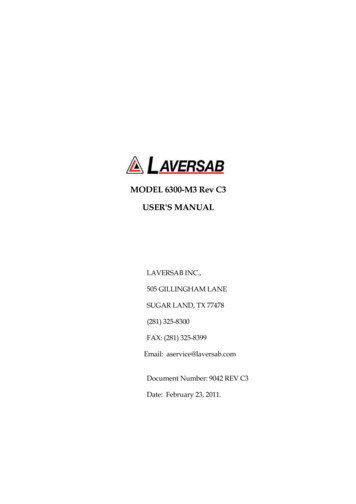
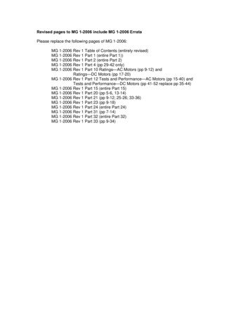
SECTION 2CONTROLS AND CONNECTIONSNote: Pt Pitot and Ps Static2.1MAIN UNIT TOP PANELThe model 6300-M4 top panel (Figure 2.1) provides easy access to all the connections.[1]AC INPUT connector :This is a 3-pin male circular connector. A power cord is provided with the 6300-M4. Thecircular connector end of the power cord needs to connected here. The power requirement ofthe 6300-M4 is 90-260 VAC, 47-440 Hz with a maximum power consumption of 150 VA.Caution: Connecting incorrect power to the 6300-M4 will cause considerable damageThe power cord is normally left connected to the 6300-M4 at the AC INPUT connector and iswrapped around two cord posts. The cord retainers on top of these posts swivel in eitherdirection and latch at 180 degree positions, allowing easy wrapping and unwrapping of thepower cord. A cord clamp allows the cord to be held in place after it is wrapped.[2]Fuse :A 5x20 mm fuse is located inside the fuse holder. The fuse is a time-delay fuse with a rating of2.0 amps, 250 Volts.[3]AC On/Off switch :This toggle switch connects (or disconnects) AC power between the AC INPUT connector andthe 6300-M4. Even when this switch is ON, the 6300-M4 becomes operational only after theOn/Off switch located on the right side of the Remote Unit is turned ON. (Push in to turnON)[4]Remote Unit connection:The 6300-M4 is provided with a 50 foot remote cable to connect to the Remote unit. The maleend of the remote cable is connected here on the top panel. The female end of the remotecable is connected to the Remote unit. This cable should be connected prior to applyingpower to the 6300-M4. This cable should not be disconnected while power is applied to the6300-M4.2
3
4
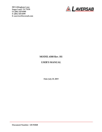
The remote cable is normally left connected to the 6300-M4 at the “Remote” connector on thetop panel and is wrapped around four cord posts on the lid of the 6300-M4 case. The cordretainers on top of these posts swivel in either direction and latch at 180 degree positions,allowing easy wrapping and unwrapping of the remote cable. A cord clamp allows the cableto be held in place after it is wrapped. It is easier to wrap the remote cable around the postsafter disconnecting the cable from the Remote unit.If the remote cable needs to be disconnected and removed from the 6300-M4 completely forstorage elsewhere then opening the Interface Connectors cover allows the cable to bedislodged from the cable guide.[5]Static ports :The Static output is provided on two ports that are internally connected. Both ports have #6AN fittings. At least one of these ports must be connected through a hose to the Static port onthe aircraft. The hose must be connected after performing the Self Test on the 6300-M4. Thehose, once connected, must not be disconnected while the aircraft Static system is not at“Ground” level. An unused port must remain closed.Caution:Do not connect the Static hose to the Static port before performing the SelfTest.Caution:Do not disconnect the Static hose from the Static port unless the aircraft Staticsystem is at “Ground” level.[6]Pitot ports :The Pitot output is provided on two ports that are internally connected. Both ports have #4AN fittings. At least one of these ports must be connected through a hose to the Pitot port onthe aircraft. The hose must be connected after performing the Self Test on the 6300-M4. Thehose, once connected, must not be disconnected while the aircraft Pitot system is not at“Ground” level. An unused port must remain closed.Caution:Do not connect the Pitot hose to the Pitot port before performing the SelfTest.Caution:Do not disconnect the Pitot hose from the Pitot port unless the aircraft Pitotsystem is at “Ground” level.5
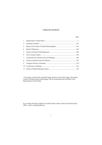
[7]RS232 interface connector:This connector is accessed by opening the “Interface Connectors” access panel as shown inFigure 2.2. The connector is a standard DB-9 female connector used for a serial RS232interface. It can be connected directly to the “COM” port of a standard PC to allowcommunication. This port is normally used for downloading “profiles” from a computer.Other remote communication with the 6300-M4 is also possible through this interface. Formore details on downloading profiles, please refer to Section 4.For more details oncommunication with the 6300-M4, please refer to Section 8.[8]Encoder interface connector:If the “Encoder” option is provided on the 6300-M4, this connector is located under the“Interface Connectors” panel as shown in Figure 2.2. This DB-15 connector is used to connectto an altitude encoder. The pin-out for this connector is provided in Appendix C. Theconnetor provides 12 volt power for the encoder and connects to the 10 output bits of theencoder. Further details on how to access the encoder’s 10-bit code and view it on the 6300M4 display, are provided in Section 3.5.9.[9]IEEE-488 interface connector:If the “IEEE” option is provided on the 6300-M4, this connector is located under the “InterfaceConnectors” access panel, as shown in Figure 2.2. The connect
MODEL 6300-M4 Rev. A3 USER'S MANUAL LAVERSAB INC., 505 GILLINGHAM LANE SUGAR LAND TX 77478 (281) 325-8300 FAX: (281) 325-8399 . Date: February 23, 2011. i WARRANTY Laversab Inc., warrants its products to conform to or exceed the specifications as set forth in its catalogs in use at the time of sale and reserves the right, at its own .