Transcription
MODEL 6300-M4 Rev. A5USER'S MANUALLAVERSAB INC.,505 GILLINGHAM LANESUGAR LAND TX 77478PHONE: (281) 325-8300FAX:(281) 325-8399Email: aservice@laversab.comDocument Number: 9043 REV A5Date: June 30th 2014
WARRANTYLaversab Inc., warrants its products to conform to or exceed the specifications asset forth in its catalogs in use at the time of sale and reserves the right, at its owndiscretion, without notice and without making similar changes in articles previouslymanufactured, to make changes in materials, designs, finish, or specifications. LaversabInc. warrants products of its own factory against defects of material or workmanship for aperiod of one year from date of sale.Liability of Laversab Inc. under this warranty shall be limited to replacing, free ofcharge (FOB Houston, Texas), any such parts proving defective within the period of thiswarranty, but Laversab Inc. will not be responsible for transportation charges,consequential or incidental damages. No liability is assumed by Laversab for damagesthat are caused by misuse or abuse of the product.The warranty of Laversab Inc. is not made for products manufactured by otherswhich are illustrated and described in Laversab catalogs or incorporated in Laversabproducts in essentially the same form as supplied by the original manufacturer.Warranties of the original manufacturers supplant the warranty of Laversab Inc., but, inapplicable instances, the latter agrees to use its best efforts to have original suppliers makegood their warranties.i
COPYRIGHT NOTICECopyright (c) 2003-2006 by Laversab Inc. All rights reserved. The content of this manualmay not be reproduced in any form by any means, in part or in whole, without the priorwritten permission of Laversab Inc.DISCLAIMERNo representations or warranties are made with respect to the contents of this user'smanual. Further, Laversab Inc. reserves the right to revise this manual and to makechanges from time to time in the content hereof without obligation to notify any person ofsuch revision.ii
REVISION HISTORYDocument No.Release DateDescription9043 REV A10/20/20036300-M4 REV A User’s Manual9043 REV A203/05/20106300-M4 REV A2 User’s Manual9043 REV A303/23/20116300-M4 REV A3 User’s Manual9043 REV A407/22/20116300-M4 REV A4 User’s Manual9043 REV A506/30/20146300-M4 REV A5 User’s Manualiii
WARNINGTHE 6300-M4 USES LINE VOLTAGES FOR ITS OPERATION WHICH AREPOTENTIALLY DANGEROUS. IMPROPER OPERATION OF THIS EQUIPMENT MAYRESULT IN PERSONAL INJURY OR LOSS OF LIFE. HENCE THE EQUIPMENTDESCRIBED IN THIS MANUAL SHOULD BE OPERATED ONLY BY PERSONNELTRAINED IN PROCEDURES THAT WILL ASSURE SAFETY TO THEMSELVES, TOOTHERS AND TO THE EQUIPMENT.BEFORE PERFORMING ANY MAINTENANCE, TURN THE POWER OFF ANDDISCONNECT THE POWER CORD FROM THE POWER SOURCE.ALWAYS USE A 3-PIN GROUNDED OUTLET AS YOUR AC POWER SOURCEiv
TABLE OF CONTENTSWarranty.Copyright notice, disclaimer .Revision History .Warning.Section 1:iiiiiiivIntroduction . 1Section 2:Controls and Connections . 22.1 Main Unit Top Panel . 22.2 Remote Unit Top Panel . 9Section 3:Understanding the 6300-M4 .3.1 Start Up .3.2 Main Operating Screen .3.2.1 Displayed Parameters .3.2.2 Target Value Entry .3.2.3 Units Selection .3.2.4 Mode Selection .3.3 Leak Screen .3.4 Self Test Screen .3.5 Function Select Screen .3.5.1 Function 1: View Limits .3.5.2 Function 2: Set Limits .3.5.3 Function 3: Set Knots Rate .3.5.4 Function 4: View and Execute Profiles .3.5.5 Function 5: Setup Profiles .3.5.6 Function 6: Height Correction .3.5.7 Function 7: Set Ground .3.5.8 Function 8: Go To Ground .Section 23233333434. 35What is a Profile .Creating a Profile .Setting Up Hyperterminal.Downloading a Profile .Executing a Profile .3537383940Section 5:Typical Use. 42Section 6:Calibration. 456.16.26.36.4Equipment .General Notes .Ps Calibration .Pt Calibration .v45454647
TABLE OF CONTENTS (contd.)Section 7:Maintenance. 51Section 8:Communication Interface . 528.1 RS232 Serial Interface . 528.2 Communication Syntax . 52Appendix A: Error Codes. 55Appendix B: Specifications . 56Appendix C: Repair and Return Policies . 57vi
SECTION 1INTRODUCTIONNote: Pt Pitot and Ps StaticThe model 6300-M4 is a high accuracy automated pressure controller, specifically designedfor controlling air data parameters such as altitude, airspeed, Mach and climb. Thisinstrument can also be used to control pressures in units of inHg and mbar. The 6300-M4 isequipped with internal pressure and vacuum pumps. The Remote unit is used to interfacewith the Main unit. The small size of the Remote unit allows it to be used in the cockpit of anaircraft.The 6300-M4 has two high accuracy transducers that measure pressure in the range of 0 to 38inHg absolute on the Ps (static) output, and 0 to 100 inHg absolute on the Pt (pitot) output.These transducers are designed to accurately measure the pressure of dry air over an ambienttemperature range of -10oC to 50oC. The 6300-M4 is RVSM compliant.The 6300-M4 allows the user to control altitude in feet or meters, climb in feet per minute ormeters per minute, airspeed in knots, mach, mph and kmph. It also allows the user to controlEPR on the pitot output.The model 6300-M4 features programmable limits on altitude, airspeed, mach number, andclimb rate. These limits are checked during data entry and thereby prohibit entry oferroneous target values. These limits are also checked continuously during operation, and ifany of these is exceeded, the unit automatically takes abortive action.The user has the ability to program into the 6300-M4 a profile of set-points to be controlled ina sequence. Once such a profile has been setup, the user can command the unit to move fromone set-point to the next simply by pushing the 'GO' button. Up to 50 points can be stored inone profile. The 6300-M4 can store up to 20 such profiles in non-volatile memory at any onetime.Calibration of the unit is required only once a year. This process is the only scheduledmaintenance function required on the 6300-M4.The model 6300-M4 comes with an RS232 interface. This interface is mainly used to downloadprofiles from a computer. Connect Power and the Remote, connect the Pitot and Staticoutputs to the aircraft, and the 6300-M4 is ready for use. It’s high accuracy and ease of usemake it the ideal Pitot Static Tester.1
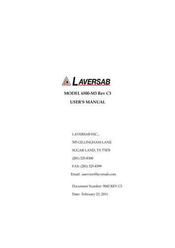
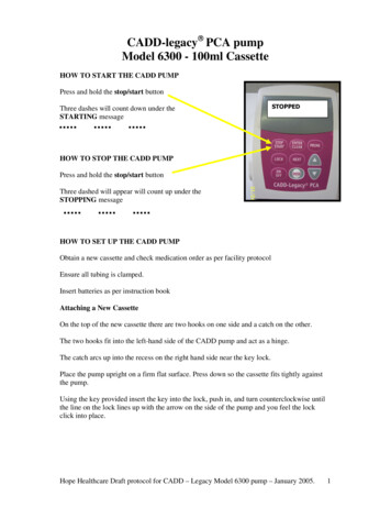
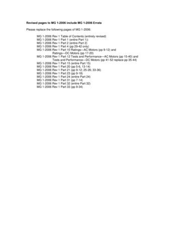
SECTION 2CONTROLS AND CONNECTIONSNote: Pt Pitot and Ps Static2.1MAIN UNIT TOP PANELThe model 6300-M4 top panel provides easy access to all the connections.Please refer to Figure 2.1.[1]AC INPUT connector :This is a 3-pin male circular connector. A power cord is provided with the 6300-M4. Thecircular connector end of the power cord needs to connected here. The power requirement ofthe 6300-M4 is 90-260 VAC, 47-440 Hz with a maximum power consumption of 150 VA.Caution: Connecting incorrect power to the 6300-M4 will cause considerable damage[2]Fuse :A 5x20 mm fuse is located inside the fuse holder. The fuse is a time-delay fuse with a rating of2.0 amps, 250 Volts.[3]AC On/Off switch :This toggle switch connects (or disconnects) AC power between the AC INPUT connector andthe 6300-M4. Even when this switch is ON, the 6300-M4 becomes operational only after theOn/Off switch located on the right side of the Remote Unit is turned ON. (Push in to turnON)[4]Remote Unit connection:The 6300-M4 is provided with a 50 foot remote cable to connect to the Remote unit. The maleend of the remote cable is connected here on the top panel. The female end of the remotecable is connected to the Remote unit. This cable should be connected prior to applyingpower to the 6300-M4. This cable should not be disconnected while power is applied to the6300-M4.2
Figure 2.1 (A)3
Figure 2.1 (b)4
The remote cable is normally left connected to the 6300-M4 at the “Remote” connector on thetop panel and is wrapped around four cord posts on the lid of the 6300-M4 case. The cordretainers on top of these posts swivel in either direction and latch at 180 degree positions,allowing easy wrapping and unwrapping of the remote cable. A cord clamp allows the cableto be held in place after it is wrapped. It is easier to wrap the remote cable around the postsafter disconnecting the cable from the Remote unit.If the remote cable needs to be disconnected and removed from the 6300-M4 completely forstorage elsewhere then opening the Interface Connectors cover allows the cable to bedislodged from the cable guide.[5]Static ports :The Static output is provided on two ports that are internally connected. Both ports have #4AN fittings. At least one of these ports must be connected through a hose to the Static port onthe aircraft. The hose must be connected after performing the Self Test on the 6300-M4. Thehose, once connected, must not be disconnected while the aircraft Static system is not at“Ground” level. An unused port must remain closed.Caution:Do not connect the Static hose to the Static port before performing the SelfTest.Caution:Do not disconnect the Static hose from the Static port unless the aircraft Staticsystem is at “Ground” level.[6]Pitot ports :The Pitot output is provided on two ports that are internally connected. Both ports have #3AN fittings. At least one of these ports must be connected through a hose to the Pitot port onthe aircraft. The hose must be connected after performing the Self Test on the 6300-M4. Thehose, once connected, must not be disconnected while the aircraft Pitot system is not at“Ground” level. An unused port must remain closed.Caution:Do not connect the Pitot hose to the Pitot port before performing the SelfTest.Caution:Do not disconnect the Pitot hose from the Pitot port unless the aircraft Pitotsystem is at “Ground” level.5
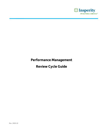
[7]RS232 interface connector:This connector is accessed by opening the “Interface Connectors” access panel.Theconnector is a standard DB-9 female connector used for a serial RS232 interface. It can beconnected directly to the “COM” port of a standard PC to allow communication. This port isnormally used for downloading “profiles” from a computer. Other remote communicationwith the 6300-M4 is also possible through this interface. Figure 2.2 shows the RS232 connector(6) with the panel removed. For more details on downloading profiles, please refer to Section4. For more details on communication with the 6300-M4, please refer to Section 8.[8]IEEE-488 interface connector:This feature is currently not available on the 6300-M4.[9]Encoder interface connector:This feature is currently not available on the 6300-M4.[10]Static Vent :In the event that the 6300-M4 is in-operable due to a malfunction or due to loss of power, it ispossible to vent the Static system manually. This is done using the metering valve labeled“Static Vent”. This valve is a positive shut-off valve. Opening this valve slowly will vent theStatic output of the 6300-M4 to ambient pressure. While venting, care must be taken to ensurethat the maximum climb rate of the aircraft connected to the tester is not exceeded. Also, thePitot Vent may need to be used to maintain the airspeed within limits of the indicator on theaircraft.Caution: The Static Vent is NOT connected to the Pitot Vent. There is NO cross-bleed.When venting is completed, close the valve.Caution: Do not over-tighten the valve as this may damage the seat of the valve.[11]Pitot Vent :In the event that the 6300-M4 is in-operable due to a malfunction or due to loss of power, it ispossible to vent the Pitot system manually. This is done using the metering valve labeled“Pitot Vent”. This valve is a positive shut-off valve. Opening this valve slowly will vent thePitot output of the 6300-M4 to ambient pressure. While venting, care must be taken tomaintain the airspeed within limits of the indicator on the aircraft.Caution: The Pitot Vent is NOT connected to the Static Vent. There is NO cross-bleed.When venting is completed, close the valve.Caution: Do not over-tighten the valve as this may damage the seat of the valve.6
Figure 2.27
Figure 2.38
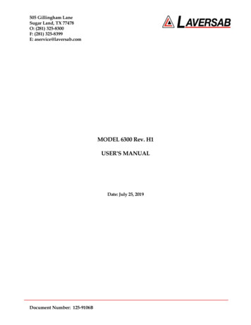
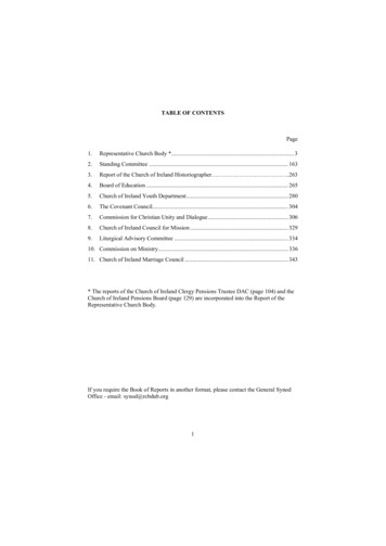
2.2REMOTE UNIT TOP PANELPlease refer to Figure 2.3 which shows the front panel of the Remote unit. The LCD displayhas 4 lines of 40 characters each. There are five function keys just below the display. NEXTSCREEN and PREVIOUS SCREEN are used to move between the different operating screensof the 6300-M4. At present there are only three upper level operating screens : Main,Calibrate and Self test.The FUNCTION SELECT key is used to go into a screen which allows the user to choose anyone of eight functions. The functions are:1.2.3.4.5.6.7.8.View LimitsSet LimitsSet Knots rateExecute profileSetup profileHeight CorrectionSet “Ground”Go to “Ground”These functions are described in detail in Section 3.The GO key is used to execute all changes made through the Remote unit. After the changeshave been 'ENTER' ed, they will flash on the screen until executed by the GO key. This allowsfor simultaneous execution of several changes in target values, modes, units etc.The CANCEL key has multiple purposes. It is used to abort all changes that are flashing onthe screen. It is also used to exit out of target value entry, unit selection and mode selection.It is used to exit out of other screens like Leak test and Function select. The CANCEL key isalso used to acknowledge error messages or exit an executing profile.NUMERIC KEYS :These keys are used for numeric entry of target values and other numeric data. The ' /-' keyoperates just like on a calculator and is used to enter negative values. This key must be usedafter entering the positive value, to make it negative.The CLR key is used to clear the data entry field.The ENTER key is used to accept numeric entries and also select units and modes.9
TARGET VALUE KEYS :There are typically 3 parameters that the 6300-M4 controls - Altitude, Climb and Airspeed.Each parameter has its own target value key. The Pt/AIRSPEED key is used to select Pt orAirspeed target value entry, the Ps RATE/CLIMB key is used to select Climb value entry, andthe Ps/ALTITUDE key is used to select Ps or Altitude value entry. After selecting the targetvalue key, the new value can be entered using the numeric keypad.The UP ARROW and DOWN ARROW keys are used to “Jog” a target value. The arrow keysare also used to move between various choices during Unit selection and Mode selection. Formore information, please refer to Section 3.2.2.UNITS SELECT KEYS :Units can be selected independently for the Pt and Ps outputs. Pressing the Pt UNITS keywill bring up the choices in Pt units onto the 4th line of the display. To exit from this selectionmode, press CANCEL. To move between the choices use the arrow keys. There are nine Ptunits in all. The cursor location is indicated by the blinking unit mnemonic. Once the cursoris on the desired units, press 'ENTER' to select that unit.The Ps UNITS key brings up the choices for Ps units onto the 4th line of the display. UseCANCEL to exit this unit selection mode. Use the arrow keys to move between the choices.Use the ENTER key to select a choice. There are four Ps units to choose from.For more information on Units Selection please refer to Section 3.2.3.MODE SELECT KEYS :These keys are used to select between one of three operating modes. Pressing these keysbrings up the selection of modes onto the 4th line of the display. The desired selection can bechosen by moving the cursor using the arrow keys and then pressing ENTER. The GO keywill execute the entered selection. Modes can be selected independently for the Ps and Ptoutputs.For more information on Mode Selection please refer to Section 3.2.4.10
SECTION 3UNDERSTANDING THE 6300-M4Note: Pt Pitot and Ps StaticThe 6300-M4 is typically used to calibrate and check air data instruments like altimeters,climb indicators, and airspeed/ Mach indicators on an aircraft. It is also used to leak-checkthe Pitot/ Static system of an aircraft. This section will explain how to use the 6300-M4 toperform these functions.3.1Step 1:Step 2:Step 3:Step 4:Step 5:START UPConnect the Remote cable to the Remote unit and the “Remote” connector onthe main unit.Check the ON/OFF switch on the Remote unit and make sure it is OFF.Remove the protective caps from one each of the Pitot and Static outputs on themain unit. DO NOT connect any hoses yet. Make certain that the outputs areopen to ambient. Close Pitot and Static Vent valves.Connect the power cable to the “AC INPUT” connector on the main unit andconnect the far end of the power cable to an AC supply.On the Main unit, turn the AC On/Off switch ON. On the Remote unit, turnthe ON/OFF switch ON.The 6300-M4 will turn ON and the Remote unit will turn ON. The display will briefly showthe sign-on screen and then go into the Main screen. The Main screen should appear min35003000Feet10050MThe Actual values shown on line 2 will be different from the ones shown. The 4th line shouldbe blank.Before actually using the 6300-M4 to perform certain tasks, it is important to understand howto use the Remote unit to make the 6300-M4 do what you want. This section explainseverything about the information that you see on the Remote unit and what it means, and11
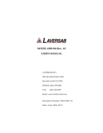
MainOperatingScreenLeak modeFunctionSelectLeakScreenFunction SelectScreens (2)1View Limits2Password34Changeknots rateExecute profile(Return to Main)5Setup Profile6Height Correction7Set Ground8Go to GroundNextScreenPasswordCalibrationNextScreenSelf TestSelf Test ProgressFigure 3.112Change Limits
how to change all the parameters that are shown on the display. As we proceed through theexplanations, it will become clearer as to how the 6300-M4 actually operates.Interaction with the 6300-M4 is done through several different screens that are displayed onthe Remote unit. All the screens are shown in Figure 3.1. Of the screens shown in Figure 3.1,the Self Test screen is used only at startup, all the Function Select screens are used only a fewtimes during normal operation and also when first setting up the 6300-M4. The Calibratescreen is used only once a year by the calibration facility. During normal operation, the twoscreens that are used the most are the Main Operating screen (Main Screen) and the LeakScreen. All the different screens, except the calibration screen, are explained in this section.The Calibration screen is explained in section 6.3.2MAIN OPERATING SCREENMost of the operation of the 6300-M4 is done in the Main Screen. All the pertinent parametersare displayed on this screen. The screen is also used to change Target values, Units, andModes. The following sub-sections explain the various uses of the Main Screen.3.2.1DISPLAYED PARAMETERSThere are 11 basic parameters of importance while using the 6300-M4. Each of theseparameters is displayed on the Main Screen. Each parameter is explained below andhighlighted in a sample screen.Parameter 1. Pitot Units: Unit of measurement for displaying the Pitot output. Normally,the Pitot unit used is ‘Knots’ for displaying airspeed. Other possible units for displaying thePitot output are shown in section 3.2.3, which also explains how to select a particular unit.The currently selected Pitot unit is shown on the first line of the display (as shown below).The two values (101.2 and 20.0) that appear below it are in these 5003000Feet10050MParameter 2. Static Units: Unit of measurement for displaying the Static output. Normally,the Static unit used is ‘Feet’ for displaying altitude. Other possible units for displaying theStatic output are shown in section 3.2.3, which also explains how to select a particular unit.The currently selected Static unit is shown on the first line of the display (as shown below).13
The two values (1005 and 0) that appear below it are in these 5003000Feet10050MParameter 3. Climb Units: Unit of measurement for displaying the rate of change of theStatic output, or Climb. Normally, the climb unit used is ‘Feet/min’ for displaying rate ofchange of altitude. These units cannot be independently chosen. Whatever the unit selectedfor the Static output, the climb unit is the per minute rate of that selected Static unit. If theStatic unit selected is ‘inHg’ then the climb unit will be ‘inHg/min’. The currently selectedclimb unit is shown on the first line of the display (as shown below). The two values (3500and 3000) that appear below it are in these 5003000Feet10050MParameter 4. Pitot “Actual” value:This is the current pressure measured at the Pitotoutput, displayed in the current units. In the sample screen shown below, the currentpressure at the Pitot output is 101.2 knots. This value is updated every 0.25 n35003000Feet10050MParameter 5. Static “Actual” value:This is the current pressure measured at the Staticoutput, displayed in the current units. In the sample screen shown below, the currentpressure at the Static output is 1005 Feet. This value is updated every 0.25 n3500300014Feet10050M
Parameter 6. Climb “Actual” value:This is the current rate of change of pressuremeasured at the Static output, displayed in the current units. In the sample screen shownbelow, the current rate of change of pressure at the Static output is 3500 feet/min. This valueis updated every 0.25 n35003000Feet1005 M0Parameter 7. Pitot “Target” value:This is the value that you command the 6300-M4 toachieve on the Pitot output. In the sample screen below, the 6300-M4 has been commanded toachieve a pressure of 20.0 knots on the Pitot output. The Pitot “Target” value is meaningfulonly when the Pitot output is in the “Control” mode. This is explained later in this section.How to change the Pitot “Target” value is explained in section 5003000Feet10050MParameter 8. Static “Target” value:This is the value that you command the 6300-M4 toachieve on the Static output. In the sample screen below, the 6300-M4 has been commandedto achieve a pressure of 0 Feet on the Static output. The Static “Target” value is meaningfulonly when the Static output is in the “Control” mode. This is explained later in this section.How to change the Static “Target” value is explained in section 5003000Feet10050MParameter 9. Climb “Target” value:This is the value that you command the 6300-M4 toachieve as the rate of change of pressure (climb/dive) on the Static output. In the sample15
screen below, the 6300-M4 has been commanded to achieve a climb of 3000 Feet/min. on theStatic output. A dive would be indicated by a negative value. The Climb “Target” value ismeaningful only when the Static output is in the “Control” mode. This is explained later inthis section. How to change the Climb “Target” value is explained in section 5003000Feet10050MParameter 10. Pitot Mode: The Pitot output can be in one of three modes –Measure (“M”),Leak (“L”), or Control (“C”).In the Measure mode, the pressure at the Pitot output is simply being measured anddisplayed as the “Actual” value in the current Pitot units. The pressure is not being changedby the 6300-M4. In this mode, the Pitot valve inside the 6300-M4 that is used to change thepressure at the Pitot output is pneumatically isolated from the Pitot output. In the Measuremode, the Pitot “Target” value is meaningless, since the 6300-M4 is not trying to achieve anyspecific target value.The Leak mode is pneumatically identical to the Measure mode. When either (Pitot or Static)output is in Leak mode, the screen changes from the Main Operating screen to the Leakscreen. The Leak screen is detailed in section 3.3.When the Pitot output is in the Control mode the 6300-M4 is actually attempting to achievethe Pitot “Target” value. The Pitot control valve inside the 6300-M4 is now connected to thePitot output and is actually increasing or decreasing the pressure to achieve and maintain the“Target” value.For an explanation of how to change the Pitot mode between Measure, Leak and Control,please refer to section 500300016Feet10050M
Parameter 11. Static Mode: The Static output can be in one of three modes –Measure (“M”),Leak (“L”), or Control (“C”).In the Measure mode, the pressure at the Static output is simply being measured anddisplayed as the “Actual” value in the current Static units. The pressure is not being changedby the 6300-M4. In this mode, the Static valve inside the 6300-M4 that is used to change thepressure at the Static output is pneumatically isolated from the Static output. In the Measuremode, the Static “Target” value is meaningless, since the 6300-M4 is not trying to achieve anyspecific target value.The Leak mode is pneumatically identical to the Measure mode. When either (Pitot or Static)output is in Leak mode, the screen changes from the Main Operating screen to the Leakscreen. The Leak screen is detailed in section 3.3.When the Static output is in the Control mode the 6300-M4 is actually attempting to achievethe Static “Target” value. The Static control valve inside the 6300-M4 is now connected to theStatic output and is actually increasing or decreasing the pressure to achieve and maintain the“Target” value.For an explanation of how to change the Static mode between Measure, Leak and Control,please refer to section 5003000Feet10050MSplit Screen:The Main operating screen displays all 11 parametersconveniently. The screen can actually b
Laversab Inc., warrants its products to conform to or exceed the specifications as set forth in its catalogs in use at the time of sale and reserves the right, at its own . The 6300-M4 allows the user to control altitude in feet or meters, climb in feet per minute or meters per minute, airspeed in knots, mach, mph and kmph. It also allows the .