Transcription
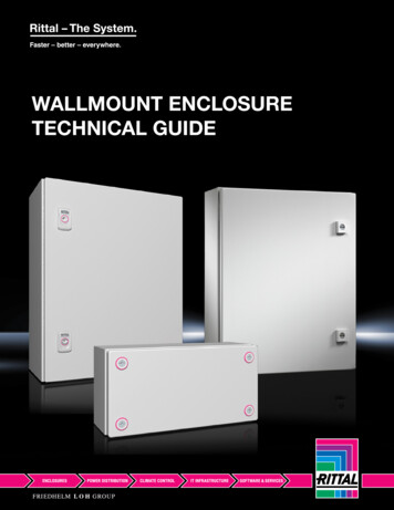
RITTALTOPTHERMSchaltschrankKühlgerätCooling oelectric CoolerSK 3201.200SK 3201.300Condizionatoreper armadiRefrigeradorpara armariosMontage-, Installations- und BedienungsanleitungAssembly and operating instructionsManuel d’installation et de maintenanceMontage- en bedieningshandleidingMontage- och hanteringsanvisningIstruzioni di montaggio e funzionamentoInstrucciones de montajeR
Before installation of the cooling unit,please read this manual completely and carefully.GBThe manual is a permanent part of the supplied systemand must be retained until the device is decommissioned.We thank you for deciding to purchase a Rittal product!The Rittal Thermoelectric Cooler is a high-performance thermoelectric light-weight cooling unit withthe highest efficiency (COP 1) of its class!The cooling unit is particularly suitable for the climatecontrol of operating housings and small enclosures!Rittal GmbH & Co. KG products are continuallyadapted to the requirements and needs of our customers. This means the information concerning theproduct characteristics and functions contained inthis manual can be changed without notice in thecase of product improvements.Before using the cooling unit, read this manual carefully in order to make full use of the excellent performance characteristics of the product.2Rittal Thermoelectric Cooler assembly and operating instructions
Contents1 Unpacking and checking. . . . . . . . . . 416 Maintenance and cleaning . . . . . . . 162 Notes on documentation. . . . . . . . . . 416.1 Maintenance . . . . . . . . . . . . . . . . . . . . . . . . 1616.2 Cleaning . . . . . . . . . . . . . . . . . . . . . . . . . . . 162.1Retention of the manual . . . . . . . . . . . . . . . . 43 Safety notes . . . . . . . . . . . . . . . . . . . . 53.13.2Proper usage . . . . . . . . . . . . . . . . . . . . . . . . . 5Standards, guidelines . . . . . . . . . . . . . . . . . . 517 Fault correction . . . . . . . . . . . . . . . . 1718 Disposal . . . . . . . . . . . . . . . . . . . . . . 1819 Guarantee . . . . . . . . . . . . . . . . . . . . . 184 How it works. . . . . . . . . . . . . . . . . . . . 65 Control . . . . . . . . . . . . . . . . . . . . . . . . 76 Device description . . . . . . . . . . . . . . . 87 Device mounting . . . . . . . . . . . . . . . . 97.17.2External mounting. . . . . . . . . . . . . . . . . . . . 10Internal mounting . . . . . . . . . . . . . . . . . . . . 108 Filter mounting. . . . . . . . . . . . . . . . . 119 Mounting of thecondensate discharge . . . . . . . . . . . 1110 Electrical connection. . . . . . . . . . . . 1210.1 Connection data . . . . . . . . . . . . . . . . . . . . . 1211 Interfaces . . . . . . . . . . . . . . . . . . . . . 1311.1 Interface X1 –power supply and alarm output . . . . . . . . . 1311.2 Interface X2 –device programming . . . . . . . . . . . . . . . . . . 1311.3 Interface X3 –integration in a higher-levelmonitoring system . . . . . . . . . . . . . . . . . . . 1312 Earth connection . . . . . . . . . . . . . . . 1313 Commissioning . . . . . . . . . . . . . . . . 1414 Status and function displays . . . . . 1415 Technical specifications . . . . . . . . . 15Rittal Thermoelectric Cooler assembly and operating instructions3GB
1 Unpacking and checking1GBUnpacking and checkingThe Rittal Thermoelectric Cooler is delivered in transport packaging.The supplied system consists of:1 x cooling unit1 x assembly and operating instructions1 x accessories bagShipping bag content:1 x assembly and operating instructions1 x self-adhesive sealing tape1 x filter mat1 x drilling template1 x connector plug (power supply and alarm output)Assembly partsCheck that the delivered system is complete and undamaged. Any obvious transport damage must bereported without delay to the responsible transportcompany.The latest version of the “General conditions fordeliveries and services” of the ZVEI (Central Association of the German Electrotechnical Industry)applies.Prior to disposal, check the packaging material forany loose function parts!2Notes on documentationAssembly and operating instructions are available inprinted form (provided with the supplied system) andas a PDF file for the Rittal Thermoelectric Cooler.A PDF file is available as free download fromwww.rittal.com. ACROBAT READER is requiredto view the file.The accompanying documentation must be observed for the assembly, installation and operation ofthe cooling unit. Rittal cannot accept any liability fordamage associated with the failure to observe theseinstructions.The information and safety notes in this manualfollow the following structure:Safety and other instructions:Danger!Warning of a potential danger source.Danger to life and health in case ofnon-observance!Danger!Warning of a dangerous electricalvoltage.Danger to life and health in case ofnon-observance!Danger!Warning of slippery surface.Danger to life and health in case ofnon-observance!Note:Useful information and special features.2.1 Retention of the manualThe operating company is responsible for retainingthe manual.No part of the manual may be reproduced orprocessed, copied or distributed using electronicsystems in any form (printed, microfilm or anyother form) without the written approval of RittalGmbH & Co. KG. No liability can be assumed forany damage resulting from the non-observanceof the information contained in this manual.4Rittal Thermoelectric Cooler assembly and operating instructions
3 Safety notes3Safety notesThe following general safety notes must be observedfor the assembly, installation and operation of thecooling unit:– The assembly, installation and servicing of thecooling unit may only be performed by properlytrained specialists.– The mains connector of the cooling unit must onlybe connected and disconnected with the systemde-energised. The device must be protected witha pre-fuse.– No changes may be made to the cooling unit.– Only the customer service or authorised personnelmay open the device. The opening of the device bythe user or unauthorised persons is not permittedand will void any warranty claim.– The cooling unit is intended only for the climatecontrol of enclosures and housings. Any other useshall be deemed improper. The manufacturer isnot liable for any resulting damage! Proper usagealso includes the observance of all valid documents and compliance with the inspection andservicing conditions.– The air inlet and outlet openings on the cooling unitmust not be covered.– Use only original spare parts and accessoriesexpressly approved for the Rittal ThermoelectricCooler. Otherwise malfunctions or damage canoccur. Warranty claims cannot be accepted forsuch damage.3.2 Standards, guidelinesThe Rittal Thermoelectric Cooler meets the requirements of the following guidelines and standards:– DIN 3168 Section 4.5 (enclosure cooling units)– Machine directive 98/37/EC– Low-voltage directive 2006/95/EC– Electromagnetic compatibility 2004/108/EC– EN 378-1 to -4 (cooling systems and heat pumps)– EN ISO 12100-1 and -2 (machine safety)– EN 294 (safety distances for contact)– EN 60 204-1 (machine electrical equipment)– EN 60 529 (degrees of protection provided by thehousing IP rating)– EN 60 335-1 and -2-40(safety of electrical devices)– EN 55 011 Kl B (radio disturbances)– EN 61 000-3-11 (electromagnetic compatibility)– ISO 9001/14001– RoHs COMPLIANT 2002/95/EC3.1 Proper usageThe Rittal Thermoelectric Cooler conforms to thecurrent state-of-the-art.The cooling unit is intended only for cooling enclosures and operating housings. Any other use shallbe deemed improper.Proper usage is possible only when all associateddocuments, and the device-specific assembly andoperating instructions are observed.The manufacturer is not liable for any damage resulting from improper use.Rittal Thermoelectric Cooler assembly and operating instructions5GB
4 How it works4The Rittal Thermoelectric Cooler uses the Peltier effect for cooling. This effect is based on the principlethat an electric direct-current flowing through a circuit consisting of two different metals causes thecooling of one contact point and the heating of theother contact points. An appropriate layout for thecooling production is designated as Peltier element.When the Peltier effect is used for enclosure climatecontrol, an air flow is fed over the upper and lowerconnection point. The heat energy is released oraccepted from the air flow to the Peltier element.The air flow that releases the heat energy to the element is introduced as cooling air flow in the enclosure or the operating housing. After the heating of thecooling air flow by the active installed equipemt, it isreturned to the cooling unit and fed for renewed cooling over the “cold” side of the Peltier element. Thisproduces an air circulation that causes the cooling ofthe enclosure or the operating housing.The air flow that accepts the heat energy from the“warm” side of the Peltier element is released aswarm air flow to the external air circuit of the coolingunit. This means the heat produced by the components in the enclosure is dissipated to the ambient airsurrounding the cooling unit.Enclosure/operating housingDivider paneln-dopedp-doped –n-dopedEnvironmentGBHow it worksp-dopedFig. 1:6Warm areaWarm areaCold areaCold areaPeltier elementFig. 2:Peltier cooling unitRittal Thermoelectric Cooler assembly and operating instructions
5 Control5ControlFan speed in the external air circuitThe Rittal Thermoelectric Cooler controls the coolingcapacity of the Peltier elements and the air throughput of the integrated fans so that the required internaltemperature of the enclosure or the operating housing is set with high accuracy. For this purpose, thedevice permanently monitors the air entry temperature at the warm air entry (internal circulation). If thistemperature exceeds a parameterised temperaturevalue (factory setting: 35 C), the device starts cooling operation. To do this, the trigger voltages of thePeltier elements and fans are corrected by a PIDcontrol so that the cooling capacity required for thecooling is always available and the cooling operationis provided with the least possible power. The redundant fans in the external air circuit of the Rittal Thermoelectric Cooler have variable air delivery rates(and consequently variable speeds) appropriate forthe required cooling capacity. If only limited or indeed no cooling capacity is required, this control behaviour can lead to a temporary inactivity of the fansin the external air circuit. This does not constitutea malfunction of the device, but rather an extremepower-saving operating state that also increases theservice life of the used fans.Note:The fan speed in the external air circuit ofthe cooling unit is matched to the currentcooling capacity requirement.Consequently, a stoppage of the fans –interrupted by periodic, short-term fanstarts – is not a malfunction of the device,but rather represents an extreme powersaving operating state!GBmax.min.Fan offCooling capacity requirementFig. 3:Control behaviour of the fans in the external air circuitRittal Thermoelectric Cooler assembly and operating instructions7
6 Device description6Device descriptionGB12389 1011124135614157Fig. 4:Device front16Fig. 5:Device rearLegend1 Status display2 Function display3 Housing4 Louvred grille5 Warm air outlet opening – external air circuit6 Cold air inlet opening with filter element(optional) – external air circuit7 Condensate discharge8 Interface X1: supply voltage and alarm output9 Interface X2: USB 2.0, type B10 Interface X3: RJ 4511 Connection diagram12 Warm air inlet opening – air internal circuit13 Earth connection14 Cold air outlet opening – air internal circuit15 Blind nut16 Rating plate (on the device lower side)8Rittal Thermoelectric Cooler assembly and operating instructions
7 Device mounting7Device mountingThe following principles must be observed for determining the mounting position on the enclosure or operating housing:The direct incidence of cold air on temperature-sensitive components must beavoided!Components with integrated fansdetermine the cooling air routing in theenclosure or operating housing.The mounting position of the cooling unitmust be chosen so that the cooling air flowsupports the heat dissipation of these components.The Rittal Thermoelectric Cooler is mounted as external or full internal mounting.The supplied drilling template must be used to fastenthe cooling unit on the enclosure or the operatinghousing.The drilling template provides dimension lines for thevarious installation options of the cooling unit.Identify appropriate lines and dimensions on thedrilling template for the required mounting type(external or full internal mounting) using figures 6and 7.Drill the required holes for fastening the cooling unitand then cut the required cut-out, including the linewidth, in accordance with the drilling template.Risk of injury!Wear protective gear (safety glasses,protective gloves) when cutting themounting cut-out and drilling thefastening holes.Carefully deburr all drilled holes andcut-outs to prevent injuries caused bysharp edges.A free space of at least 100 mm is requiredin front of the air inlet and outlet openings ofthe cooling unit in the internal and externalcircuit.The cooling unit must be positioned onthe enclosure so that the condensate discharge opening is located at the lowestpoint of the cooling unit.Climate control unit external contourClimate control unit external contour25251004003774003663773861515154025Ø 6.5Mounting cut-out and hole sizesfor external mountingRittal Thermoelectric Cooler assembly and operating instructions18858.510811125125Fig. 6:12.57108121008.5Ø 121012.511.511.52525Ø 6.5Fig. 7:Mounting cut-out and hole sizesfor internal mounting (full internal mounting)9GB
7 Device mounting7.1 External mountingWhen the cooling unit is mounted as externallymounted variant, the supplied self-adhesive sealingtape must be fastened on the device rear wall of thecooling unit so that no gaps result at the joint edges.Then screw the supplied studs into the blind nuts atthe rear of the unit. Secure the cooling unit using thesupplied washers and nuts.Externalmounting,verticalmax. 45 almax. 45 max. 45 Fig. 11:Internalmounting,horizontalmax. 45 Permissible mounting positions7.2 Internal mountingFig. 8:Position of the sealing tapeFig. 9:Fastening the cooling unitFor the full internal mounting of the cooling unit, thelouvred grille must be carefully removed from the device. The self-adhesive sealing tape supplied mustbe placed on the front of the cooling unit (the deviceface from which the louvred grille has been removed) so that no gaps result at the joints. Thenscrew the supplied studs into the blind nuts at thefront of the unit. Secure the cooling unit using thesupplied washers and nuts. To complete the mounting, the louvred grille must be re-attached.External mounting Internal mounting15510055Position of the sealing tapeFig. 13:Fastening the cooling unit400Fig. 12:10040012555GBFig. 10:10External and internal mountingRittal Thermoelectric Cooler assembly and operating instructions
8 Filter mounting8Filter mountingThe Rittal Thermoelectric Cooler can be equippedwith a device filter (supplied).An appropriate filter unit is recommended when thecooling unit is used in ambient air subject to dust.9Mounting thecondensate dischargeGBThe Rittal Thermoelectric Cooler is equipped witha condensate discharge.Note:When a filter unit is used, it must be cleanedregularly or, if necessary, replaced.When a filter is installed, the lower louvred grille inthe air inlet of the cooling unit must be removed. Todo this, raise the louvred grille with a light tug at themarked position (see Figure 14) and withdraw it atthe front. Then place the filter mat in the filter holderof the device. The colour-marked side of the filter matmust face the device. Then re-mount the louvredgrille and snap it into position by applying light pressure.CondensatedischargeFig. 15:Condensate dischargeThe controlled condensate discharge requires acondensate discharge hose be connected to thecooling unit’s condensate discharge supports.The condensate hose is available as accessory.The installation of the condensate hose requiresthat it– is laid with a gradient (no siphon formation),– does not have any kinks,– must not have a reduced cross-section if extended.Risk of injury!The operation of the cooling unit withoutcontrolled condensate discharge cancause liquid to accumulate below thedevice.Fig. 14:Removable louvred grilleRittal Thermoelectric Cooler assembly and operating instructions11
10 Electrical connection10 Electrical connectionGBDanger!Warning of a dangerous electricalvoltage.Danger to life and health in case ofnon-observance!The Rittal Thermoelectric Cooler is available asversion with integrated multi-range power pack(100 – 240 V) and as 24 V variant (without integratedpower pack).MainsPEAlarmL1 N PEX110.1 Connection data– The mains voltage and frequency must correspond to the values stated on the rating plate.– An all-range fuse specified on the rating plate mustbe connected upstream as line and device protection.– No additional temperature control is allowed to beconnected upstream of the cooling unit on thesupply side.– An isolating device that ensures a contact openingof at least 3 mm in switched-off state must beconnected upstream of the cooling unit.– The mains connection must ensure low-noisepotential equalisation.A2PE12X2X3MS1Serial3 –11 2 3 – PEPower23H1H2NTC O YELLOWA1NTC N WHITETE1 2M2.11 2 3 4TEFig. 17:NTC I REDM2.21 2 3 42B12B22B3M41 2 3 4MMMM2.1M2.2M4SK 3201.200 connection diagram,with integrated power packMainsPEAlarmX1PE – PE 11 2 3 – PEPower12X2X3MS1Serial323H1H2NTC I REDNTC O YELLOW2B12B2A1TE1 2Fig. 16:Rating plateTEFig. 18:M2.11 2 3 4M2.21 2 3 4M41 2 3 4MMMM2.1M2.2M4SK 3201.300 connection diagram,without integrated power packLegendA1Power PCBA2Power packB1Temperature sensor, internal temperatureB2Ambient temperature sensorB3Temperature sensor, power packH1/H2 Status and function displayM2.1Condenser fan 1M2.2Condenser fan 2M4Evaporator fanTEThermoelectric elementsX1Terminal stripX2USB connectionX3Optional interface12Rittal Thermoelectric Cooler assembly and operating instructions
11 Interfaces11 InterfacesNote:The electrical signals at the interface X3are extra-low voltages (not extra-low safetyvoltages in accordance with EN 60 335).0322231Connection terminal designation SK 3201.300X124 V DCX2 X3 – PE 1 2 3Interface X1Interface X2Interface X312 Earth connectionX1L1L2PE 1 2 3NInterface X1Fig. 19:X2 X3Interface X2Interface X3Designations of the device interfaces03222310322416Connection terminal designation SK 3201.200The Rittal Thermoelectric Cooler is equipped with apotential equalisation connection point. A conductorwith a nominal cross-section of at least 6 mm2 mustbe connected to this connection point and includedin the provided potential equalisation.X124 V DCPE 1 2 3X2 X311.1 Interface X1 –power supply and alarm output– Power supplySK 3201.200: AC: 100 – 240 V, 50/60 HzSK 3201.300: DC: 24 V (SELV)– Change-over contact/alarm output (floatingconnection)Switching load: AC: 250 V/2 A, DC: 6.30 V/2 AThe signal relay releases for overtemperature,sensor break and fan failures.Pin 1Pin 2Pin 3Contact point forthe potential equalisationFig. 20:Change-over contact assignment11.2 Interface X2 –device programming– USB 2.011.3 Interface X3 –integration in a higher-levelmonitoring systemFig. 21:Contact point for potential equalisationNote:According to the standard, the PE conductor in the mains connection cable is notclassified as an equipotential bonding conductor.– RJ 45The interface X3 permits the connection of the cooling unit in higher-level monitoring systems.Rittal Thermoelectric Cooler assembly and operating instructions13GB
13 CommissioningGB13 Commissioning14 Status and function displaysThe Rittal Thermoelectric Cooler is operational immediately after connection of the power supply. If thefactory setting is unchanged, the temperature control of the enclosure or operating housing uses thefollowing parameters:The Rittal Thermoelectric Cooler is equipped witha status and function display. Two coloured LEDsshow the status, alarm and error messages that indicate the operating state of the cooling unit.Set enclosure interior temperature: 35 CStart temperature for cooling operation: 35 COvertemperature alarm message: 45 CStatusdisplayUnder normal operating conditions, device operation with unchanged factory setting should ensure aproblem-free enclosure climate control. If it wouldappear to be useful to change the predefined parameters for special climate control requirements,this can be realised with programming software. Inthis case, please contact the device manufacturer.FunctiondisplayFig. 22:Status and function displays on the cooling unitFunction LEDDescriptionOffUnit OFF or Cooling OFFGreenCooling operation ONRedError – unitTab. 1: Function displayStatus LEDDescriptionOffUnit OFFGreenUnit OKOrangeWarning (temperature alarm,temperature alarm value)RedError (sensor defective, fandefective, thermoelectric moduledefective)Tab. 2: Status display14Rittal Thermoelectric Cooler assembly and operating instructions
15 Technical specifications15 Technical specificationsModel No. SK3201.200GB3201.300W 125H 400D 155Dimensions in mmOperating voltage in volts, Hz.Useful cooling output Qkin accordance with DIN 3168L 35100 WL 35100 – 240 V AC, 50/60 HzPower consumption Pelin accordance with DIN 3168L 35Max. 100 WL 35Refrigeration factor (max.)/COPL 351.0L 351.2Power packIntegralHousing colourRAL 7024/anodised aluminiumProtection categoryaccording to EN 60 52924 V DC–Internal circuit IP 54External circuit IP 34Weight3.0 kgNoise levelMax. 63 dB(A)Operating temperature 5 C to 55 CStorage temperature–20 C to 70 CInstallation position2.4 kgHorizontal or verticalInternal circuit 132 m3/hExternal circuit 132 m3/hAir throughput, unimpeded air flowTemperature setting range 20 C to 55 CCooling activation temperature 35 C (factory setting)Type of connectionPlug-in terminal stripPre-fuse gG2AFloating change-over contact;contact loadingDC: 6.30 V / 0.1.2 AAC: 250 V / 2 A10 ATechnical modifications reserved.Tab. 3: Technical specificationsVariableRangeDefault valueEEPROMTemperature conversion C/ F0.10 ( C)YesCooling setpoint 20 to 55 C35 CYesOvertemperature alarm message(0)2.15 K (0 off)10 KYesInternal fan deactivation (during cooling pauses)0.10 (no deactivation)YesCooling output in WTab. 4: Setting ranges16014012010080Ti6040200202530354045Ambient temperature in CTi Enclosure internal temperature ( C)Room temperatureFig. 23: Cooling output characteristic curve for full internal mounting and an enclosure internal temperature Ti of 35 CRittal Thermoelectric Cooler assembly and operating instructions15
16 Maintenance and cleaning16 Maintenance and cleaningGBDanger!Prior to any cleaning or maintenancework, the power to the cooling unit mustbe disconnected!16.1 MaintenanceThe Rittal Thermoelectric Cooler is low-maintenance.Note:When the filter is replaced, use only filtermaterials approved for the Rittal Thermoelectric Cooler.The dust collecting efficiency and duststorage capacity of the filter equipmentchosen is matched to the rated flow speedof the cooling unit in the external air circuitand so guarantees an excellent dustfiltering for a high useful cooling output.16.2 CleaningIf the Rittal Thermoelectric Cooler is used in ambientair subject to dust, dust can accumulate in the areaof the air inlet and outlet openings and on the heattransferring surfaces of the Peltier element. This cancause a reduction of the air flow in the device andthus a gradually reducing cooling capacity. To remove the dust, withdraw the louvred grille at the device front side. Blow compressed air through the airinlet and outlet openings of the cooling unit.If the Peltier cooling unit is equipped with a devicefilter, it must be cleaned or replaced regularly. Thefilter mat can be cleaned by washing, dusting orblowing with compressed air. The high-quality filtermaterial used for the mat means the cleaning doesnot impair the filter-technical properties and the formstability. The fire class remains unchanged!16Rittal Thermoelectric Cooler assembly and operating instructions
17 Fault correction17 Fault correctionGBFault descriptionPossible causeCorrectionThe unit does not switch on.No power supply.Check the mains connection and thepre-fuse.The unit does not cool adequately.The air circulation in the enclosure isimpaired.Check the air circulation inside theenclosure. Check, in particular, thosecomponents equipped with a fan.Check the free spaces above andbelow the main heat dissipationsources.Ambient temperature too high.Reduce the ambient temperature.Protect the unit from radiation heatcaused by direct sunshine and hotsurfaces.Filter equipment contaminated.Check the filter and, if necessary,clean or replace.Internal fan defective.Replace (Rittal Service).External fan defective.Replace (Rittal Service).The heat produced in the enclosureexceeds the cooling capacity of thePeltier cooling unit.Reduce the heat loss.Enclosure leakages.Check the enclosure for leaks (IP 54).Check, in particular, the cable entrypoints for leaks.Internal temperature of enclosure settoo low.Check the set enclosure internaltemperature (factory setting: 35 C).Condensation.Tab. 5: Fault correctionRittal Thermoelectric Cooler assembly and operating instructions17
18 DisposalGB18 Disposal19 GuaranteeTo ensure the material reuse of the recyclable packaging materials, they must be delivered to the localcollection sites.The cooling unit must be delivered to a waste management service provider that ensures the correctreuse of the recyclable parts and the proper disposalof the rest.Provided the unit is used correctly (refer to theoperating instructions), Rittal gives its customersa 24-month “Rittal manufacturer’s guarantee”starting with date of manufacture.18Rittal Thermoelectric Cooler assembly and operating instructionsIf, within the guarantee period, during the 24 monthsafter manufacture, a malfunction occurs on the product that substantially adversely affects its functionality, Rittal will, within a reasonable period of time, rectify the malfunction by telephone service or, if necessary, by replacement, repair or other measures, at itsoption. If this is inappropriate for the customer, Rittalalso has the possibility to provide the customer withthe replacement parts required to correct the malfunction.Within the scope of its guarantee, Rittal will bear allcosts concerning the dispatching, deployment andaccommodation of its staff and with replacing or repairing any parts, provided the malfunction occurredduring the proper usage of the products and provided the costs are not increased by the movement ofthe products to a place other than that where theywere originally delivered. In addition, Rittal will bearthe necessary costs for procuring and delivering thereplacement parts to the place where the productswere originally delivered.Any parts delivered for or in replacement will be newor in mint condition and in a fully functional state freeof faults; the replaced parts will become Rittal’sproperty; the customer warrants that no rights of anythird parties will obstruct that exchange and transferof title.Any claims based on this guarantee are to be submitted to Rittal in writing within one month after theoccurrence of the malfunction.Any further claims, in particular claims for damages,are not covered by the guarantee. The statutory liability for defects is not affected by the guarantee.
Schaltschrank-SystemeIndustrial EnclosuresCoffrets et armoires électriquesKastsystemenApparatskåpssystemArmadi per quadri di comandoSistemas de armariosStromverteilungPower DistributionDistribution de ne di correnteDistribución de corrienteElektronik-Aufbau-SystemeElectronic PackagingElectroniqueElectronic Packaging SystemsElectronic PackagingContenitori per elettronicaSistemas de montaje para la electrónicaSystem-KlimatisierungSystem Climate atiseringSoluzioni di climatizzazioneClimatización de sistemasIT-SolutionsIT SolutionsSolutions ITIT-SolutionsIT-lösningarSoluzioni per ITSoluciones TI322 194Communication SystemsCommunication SystemsArmoires outdoorOutdoor-behuizingenCommunication SystemsSoluzioni outdoorSistemas de comunicaciónRittal GmbH & Co. KG · Postfach 1662 · D-35726 HerbornTel.: 49 (0) 2772 505-0 · Fax: 49 (0) 2772 505-2319 · eMail: info@rittal.de · www.rittal.comR02/09Switch to perfection
2 Rittal Thermoelectric Cooler assembly and operating instructions GB Before installation of the cooling unit, please read this manual completely and carefully. The manual is a permanent part of the supplied system and must be retained until the device is decommissioned. We thank you for deciding to purchase a Rittal product!