Transcription
Managing DRAM Latency Divergence in IrregularGPGPU ApplicationsNiladrish Chatterjee †§ , Mike O’Connor†k§ , Gabriel H. Loh‡, Nuwan Jayasena‡ and Rajeev Balasubramonian Universityof Utah † NVIDIA ‡ Advanced Micro Devices, Inc. (AMD Research) k University of Texas at AustinAbstract—Memory controllers in modern GPUs aggressivelyreorder requests for high bandwidth usage, often interleavingrequests from different warps. This leads to high variance in thelatency of different requests issued by the threads of a warp.Since a warp in a SIMT architecture can proceed only when allof its memory requests are returned by memory, such latencydivergence causes significant slowdown when running irregularGPGPU applications. To solve this issue, we propose memoryscheduling mechanisms that avoid inter-warp interference inthe DRAM system to reduce the average memory stall latencyexperienced by warps. We further reduce latency divergencethrough mechanisms that coordinate scheduling decisions acrossmultiple independent memory channels. Finally we show thatcarefully orchestrating the memory scheduling policy can achievelow average latency for warps, without compromising bandwidthutilization. Our combined scheme yields a 10.1% performanceimprovement for irregular GPGPU workloads relative to athroughput-optimized GPU memory controller.I.I NTRODUCTIONThe energy efficiency of Graphics Processing Units(GPUs) [28] and the development of high-level parallel programming models such as CUDA [39] and OpenCL [29] haveled to the increasing adoption of the GPU for running dataparallel workloads. The most recent energy-efficient supercomputers all rely heavily on general purpose GPUs (GPGPUs)to scale up their parallel and floating point throughput [19].Efforts to scale GPU performance and energy-efficiency arecritical to enabling the next-generation of Exascale supercomputers [5].The data-parallel, SIMD nature of GPU architectures havetraditionally been optimized for dense, highly-structured workloads common in graphics applications. There has been considerable effort in recent years, however, to develop GPUimplementations of a wide variety of parallel algorithms fromthe High Performance Computing (HPC) and the enterprisedomains. Many of these applications are irregular and exhibitcontrol flow and memory access patterns that are not readilyamenable to the GPU’s architecture [12], [21], [34], [36]. Inparticular, many of these new irregular applications demonstrate significant Memory Access Irregularity (MAI) [11] thatleads to performance bottlenecks [9]. The memory accessesin these programs are often data dependent, and they tend tohave less spatial locality compared to traditional graphics andregular general-purpose GPU applications.One source of MAI-induced performance degradation is theSingle-Instruction, Multiple-Thread (SIMT) execution modelof GPUs. In the GPU, each SIMT core runs a group ofthreads (a warp) in lockstep. When a warp issues a loadinstruction, the warp will block once an instruction dependent§ Authorswere employed at AMD Research when this work was done.SC14, November 16-21, 2014, New Orleans978-1-4799-5500-8/14/ 31.00 c 2014 IEEEupon the load data becomes the next to issue. This warp isunable to make progress until all the data for the constituentload instructions is available. Given the SIMT architecture, asingle delinquent load can block forward progress of the warp.This introduces the problem of memory latency divergence– a warp can be stalled until the last memory request froma vector load instruction is returned, potentially long afterother memory requests from the vector load have completed.In many workloads, this load latency cannot be hidden byexecuting other warps. Several studies have highlighted howmemory latency divergence can be a significant performancebottleneck in GPUs [35], [45]. This problem of memorylatency divergence is not unique to GPUs and can also manifestitself in other SIMD/vector architectures that support “gather”load operations (e.g. [2]).Memory latency divergence arises from several factors.First, the cache hierarchy can service different requests atdifferent times due to hits and misses at various levels. Second,current GPU memory controllers are primarily optimized tosupport traditional, structured workloads with low degrees ofMAI. These modern GPU memory controllers will extensivelyre-order incoming requests to maximize memory system bandwidth with no explicit policy to manage the relative servicetime of different requests from the same warp. The out-oforder service can often delay a subset of the requests fromone warp while memory requests for other warps (and otherGPU functions) are serviced.In this paper, we focus on reducing the latency divergencearising from DRAM accesses due to the memory controller’sscheduling decisions. We focus on the main memory systembecause it is the source of the most significant portion ofmemory latency divergence. While cache hits can cause somerequests to be serviced with relatively low latency, the concurrent execution of thousands of threads in a GPU causes cachesto have poor hit-rates. Consequently, several requests for awarp will often be serviced at the memory controllers. Throughan opportunity analysis we show that if a system couldeliminate all main memory latency divergence, then overallGPU performance improves by 43%. Consequently, the cruxof our proposals focus on enabling the memory scheduler toensure that different requests from a warp are serviced together,or in quick succession, without interference from other warps.To achieve this objective, we propose handling the requestsfrom a warp loosely as a single group (called a warp-group)at the memory controller. We then use a novel prioritizationscheme between different warp-groups to reduce the averagememory-induced stall time for all warps (Section IV-B). Wealso observe that a significant fraction of warps issue requeststo multiple memory channels. In a baseline GPU, each channeloperates completely independently and thus requests issuedby the same warp encounter different latencies at differentcontrollers. We show that if the memory controllers are able
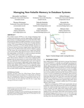
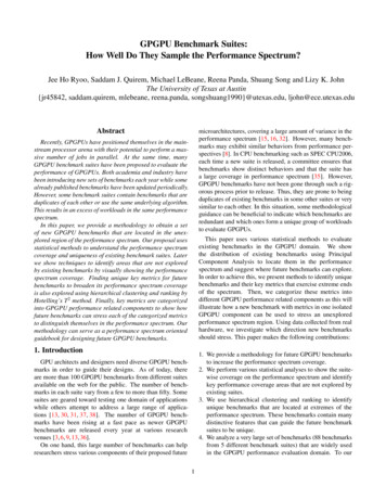
to exchange limited information to coordinate their schedulingdecisions, we can achieve further reductions in latency divergence (Section IV-C). In essence, by exchanging informationbetween GPU cores and memory controllers, we are enablingwarp-aware memory controllers.While reducing latency divergence is important for irregular GPGPU applications, bandwidth is still a first-order concernfor applications both with and without MAI. We address thisissue in two ways. First, the prioritization function describedin Section IV-B ensures that when warps exhibit row-localityat the DRAM (as in regular GPGPU compute applicationsand graphics applications), the proposed scheduler works atleast as well as a bandwidth-optimized baseline. Second, forapplications with MAI, we relax the requirement of servicingall of a warp’s requests in perfect succession. We formulate apolicy (Section IV-D) that achieves high bandwidth utilizationand reduced average warp completion times by overlappingrow-hit requests from one warp with row-miss requests fromother nearly-complete warps. Finally, we augment our warpaware scheduler to also be aware of upcoming write drainperiods in the memory system (Section IV-E). Our combinedpolicies achieve a 10.1% performance improvement over athroughput optimized baseline, and a 7.3% improvement overa previously proposed SIMT-aware memory scheduler.II.BACKGROUNDIn this section, we take a brief look at the typical architecture of a modern GPU and its DRAM scheduler.A. GPU CoresA GPU consists of a number of compute cores (StreamingMultiprocessor or SM in NVIDIA parlance) each of whichis assigned one or more groups of warps to execute. EachSM consists of multiple SIMD lanes (we model 32 lanes) andthreads in a warp are run on these lanes in lockstep. On aload instruction, each lane generates a memory request andthe warp is blocked till all the requests are serviced by thememory.B. Memory SystemThe SMs have private L1 caches and are connected todifferent memory partitions through a crossbar interconnect.Each memory partition consists of a slice of the shared L2cache and a GDDR5 channel (we model 6 memory channelsfor our studies). Each GDDR5 [23] channel is typically 64-bitswide with the command and address bus running at 1.5 GHz.The data bus runs at 3 GHz and is DDR. Each GDDR5 chiphas 16 banks and we consider two x32 GDDR5 devices perchannel that are operated in tandem as one rank. The GDDR5chip architecture is specialized for high bandwidth. It hashigher bank counts, the banks are organized into bank-groupsthat accommodate lower bank-conflict delays between differentbank groups, a higher I/O frequency, and a more robust powerdelivery network that allows more frequent row-activationscompared to DDR3 (i.e., enabling a lower tFAW ). We modelall of these aspects in our simulations (Section V).Fig. 1.Baseline GPU Memory ControllerC. Baseline Memory Controller OrganizationMemory controllers in throughput processors are optimizedto provide high bandwidth. Fig. 1 shows the components of atypical GPU memory controller (GMC) that we model as thebaseline for our studies.The Read Queue 1 and the Write Queue 2 buffer theread and write requests received from the interconnect alongwith associated information such as address, requester (SMid), and arrival timestamp. As requests arrive, they are sortedby their bank and row addresses, and entered into the RowSorter 3 . The row sorter may have (say) eight entries perbank, representing pending requests to different rows in thatbank. Each new request is merged with an existing entry (toform a stream of row-hit requests) or creates a new entry in therow sorter. The Transaction Scheduler 4 picks requests fromthe row-sorter and enqueues the commands required to complete the request in the corresponding Command Queue 5 .The transaction scheduler picks a row-hit stream from therow sorter to service in each bank and interleaves requests todifferent banks, thus exploiting row-buffer locality and banklevel parallelism. To limit latency, the transaction scheduleralso attempts to prevent the starvation of older row-missrequests by using an age-based prioritization threshold, as wellas a maximum row-hit streak limit.Write requests to DRAM are the result of write-backsfrom the last level cache and are not on the critical path forprogram execution. Writes are buffered in the write queue andare drained when the write queue occupancy rises above ahigh water mark or when there are no requests in the readqueue [14], [48]. The write requests are typically draineduntil the write queue occupancy reaches a low water mark.This mechanism ensures that the bus does not frequentlyalternate between reads and writes, thus reducing the DRAMbus turnaround penalties (tWTR).The Command queues are maintained on a per-bank basis(since most GPUs only have a single rank on a channel)and store the DRAM commands (e.g., ACT, PRE, COL RD,COL WR) for transactions that have been scheduled by thetransaction scheduler. The Command Scheduler 6 is responsible for issuing the DRAM commands to the GDDR5 chips.The command scheduler enforces low-level command timingrestrictions and tracks the state of the different DRAM banks.It iterates over the different queues to interleave requests todifferent ranks/banks so as to leverage bank-level parallelism.However, within a bank, it issues commands in queue order to
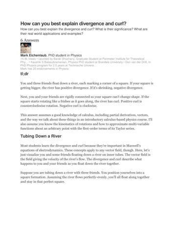
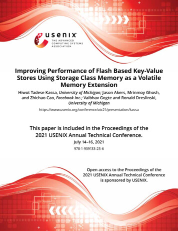
extremely effective for traditional compute workloads from theCUDA SDK [39], but its effectiveness falls short for workloadswith irregular memory accesses. Fig. 2 shows that 56% ofloads (the black bar) issued by irregular programs result inmore than one memory request and that on average each loadgenerates 5.9 memory requests after coalescing (benchmarksand evaluation techniques explained in Section V). This showsthat innovations beyond the coalescer are needed to handlememory divergence for irregular applications.Fig. 2.Coalescing efficiency.avoid disrupting the scheduling decisions taken by the transaction scheduler. The bank-group architecture of GDDR5 has theadvantage of lower inter-command delays when commands areissued to different bank groups [23]. The command schedulerthus tries to interleave requests between different bank groupsfirst and then within each bank group through a multi-levelround-robin policy.In GPUs, the address mapping policy is designed to harvestspatial locality in the access stream and high parallelism acrosschannels, ranks, and banks. First, consecutive cache lines aremapped to the same row in the same bank to promote rowbuffer locality. To exploit bank- and channel-level parallelism,blocks of consecutive cache-lines are interleaved across thememory channels and banks at a granularity of 256 bytes.In addition, to prevent pathological channel camping, whereunusual access strides lead to excessive contention on oneor few of the six simulated channels, the channel address isformed by XOR-ing a subset of higher-order bits with somelower order bits to provide a better spread across the channelsas follows:channel address {addr[47:11]:(addr[10:8] XOR addr[13:11])} % 6Similarly, to prevent strided accesses from camping on thesame bank, the bank address is formed by XOR-ing the bankaddress bits with a portion of higher-order address bits fromthe cache set index [53].III.M OTIVATIONA. Architectural Influences on Memory Latency DivergenceIn this section we look at the architectural features in GPUsthat affect memory latency divergence (besides the obviousSIMT execution model) and those that try to mitigate latencydivergence.Memory Coalescing: A common architectural technique thatreduces memory bandwidth demand in SIMD architectures ismemory coalescing. In this technique, the individual requestsfrom a warp are combined, based on their target address, toform as few cache-line sized (128B) requests as possible. Coalescing is primarily designed to reduce bandwidth requirementsby eliminating redundant accesses to the same cache line.However, it also reduces the opportunity for memory latencydivergence by minimizing the number of distinct memoryrequests per warp. Coalescing is not effective, however, ifthe data touched by the threads in a warp are not spatiallycolocated, as is commonly the case in irregular applications.Based on our simulations, we found that the coalescer isGPU memory schedulers: A warp’s requests arrive at thememory controller within short intervals of each other. So, ata first glance, it might seem that a scheduler that processesrequests in arrival order would have the effect of servicinga warp’s requests (a warp-group) together. However, in practice, the requests from different SMs arrive at the memorycontroller through the interconnect after L1 and L2 lookups.Thus, memory accesses from different warps intermingle atthe read queue and this interleaving renders a simple FirstCome, First-Serve (FCFS) policy ineffective. Also, while thetransaction scheduler may process a warp-group in a roughlyFCFS manner, the individual requests will get placed in perbank queues that may have different occupancies. As a result,the warp’s requests do not complete within short intervalsof each other under the FCFS policy. Further, a naive FCFSpolicy leads to extremely poor bandwidth utilization. A simpleFirst-Ready First-Come-First-Served (FR-FCFS [42]) or thestate-of-the-art GMC scheduler will be much more bandwidthefficient, but will aggressively re-order requests to maximizerequests to open DRAM rows. If all the requests from a warpare targeted to the same row in the same bank, a FR-FCFS orGMC policy will naturally yield most of the benefits of a warpaware policy. We observed, however, that warps in irregularGPGPU programs often issue requests to different rows, banks,and channels of DRAM. On average, a warp touches 2 banksand out of its requests, only 30% belong to the same DRAMrow. This was also observed by Lakshminarayana et al. in aprevious study [32]. These request characteristics require aneffective warp-aware scheduler to consider bank occupancies,memory intensity of warps, and write queue drain policiesto reduce latency divergence and simultaneously maintaingood bandwidth utilization for regular compute and graphicsworkloads.Multithreading: GPU SIMD cores leverage thread-level parallelism to hide memory access latency. The effect of longdivergence-induced stalls can be mitigated if there are enoughready warps in the system to hide the latency of the slowestrequest. Previous studies [18], [27] have shown, however, thatin spite of having a large number of thread contexts to choosefrom, a GPU SIMD core will frequently sit idle as all thewarps are stalled on pending memory accesses. For instance,recent NVIDIA GPUs support at most 48 to 64 warps withina compute unit [1], while main memory latencies have beenmeasured to exceed 400 cycles [22]. Thus, it is clear threadlevel parallelism cannot always completely hide main memoryaccess latency [7].Caches: Average memory latency can be improved withcaching. Requests from a warp that hit in a cache can bereturned sooner. Furthermore, the corresponding reductionof traffic that would otherwise be serviced at the memorycontroller allows other requests to be serviced with reduced
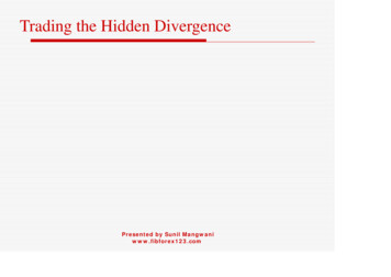
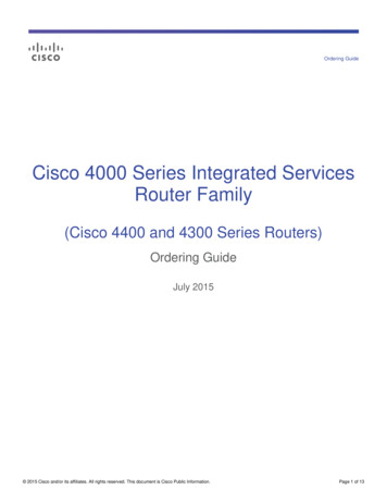
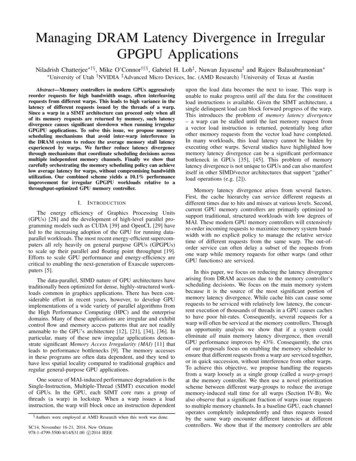
Fig. 3.Extent of memory latency divergence.Fig. 4.Room for improvement.queuing latency and contention for DRAM resources. Formemory latency divergence to be meaningfully addressed withcaches, a substantial fraction of warps must be able to serveall of their memory requests with cache hits. Otherwise, thecache misses for a warp-group will be serviced by the memorycontroller, and face issues described above. Schemes thatexploit better utilization of the cache space [43], [44] mayprovide synergistic benefits with the memory-controller-basedproposals in this work.B. Quantifying Memory Latency DivergenceThe performance penalties associated with memory latencydivergence have been documented in recent work [35], [45]. Inthis section, we further analyze the impact of DRAM latencydivergence, particularly on workloads that exhibit MAI.Main Memory Latency Divergence. To assess the scope ofmain memory latency divergence, we measure the average gapbetween the first and last request served by the main memoryfor each warp (Fig. 3, showing results only for benchmarksthat generate more than one memory request on average perload after coalescing). This provides an estimate of the mainmemory latency divergence in each benchmark. We see thaton average, the last request’s latency is 1.6 the latencyof the first request. This is the latency as seen by the SMand includes arbitration, interconnect, L2 lookup, and queuingdelays at the memory controller. The latency of a DRAMrequest is dependent on the memory controller’s schedulingpolicy. The GMC scheduling policy is optimized to increasethroughput and save power. It does not currently service therequests from a single warp together or in quick succession.If a subset of the memory requests belonging to a warp arede-prioritized by a scheduler (e.g., because they caused rowbuffer misses), then the warp’s progress is hampered. A warpwith a high number of row-buffer hit requests can unduly stalla warp with fewer, but low-locality requests. Also, interleavingrequests from two different warps can increase the stall-time ofthe last request from both warps. This increases the averageeffective memory latency experienced by both warps. If therequests from one of the warps could finish in close successionwith little interference from the other, then the overall averagememory-related stall time for the system would be reduced.The situation is made worse if requests from a warp are sentto different memory controllers. The memory controllers takescheduling decisions independent of each other based on theirlocal load and request characteristics. Fig. 3 shows that eachwarp touches 2.5 memory controllers on average and motivatesthe need for coordination between the memory controllers toFig. 5.Avoiding Inter-Warp Interference to Reduce Average EffectiveMemory Stall Timereduce latency divergence.Performance Impact of Memory Latency Divergence. Toestimate the impact of memory latency variation, we lookat two hypothetical systems. In Fig. 4, the first bar (PerfectCoalescing) shows the performance improvement that could beachieved if every warp generated exactly one memory accessper load instruction. This leads to a 5 speedup over thebaseline system. This is obviously an unrealizable system. Thesecond bar (Zero Latency Divergence) shows the performanceimprovement that can be obtained if all memory requestsfrom a warp could be returned to the SM in close successionwithout any gaps between them after the first request hasbeen serviced - in essence, if there was no main memorylatency divergence. The 43% improvement demonstrated bythis experiment represents the upper bound of the improvementthat can be obtained by eliminating memory latency divergencein GPUs. It is important to note that this model abstracts awaythe bank conflicts for all but one request for each warp, butstill faithfully models DRAM bus bandwidth and contention.Thus, while a real-world warp-aware main memory systemis unlikely to achieve these ideal benefits, the results areencouraging as they indicate significant opportunity for warpaware management of DRAM.IV.WARP -AWARE M EMORY S CHEDULINGA. Key IdeaThe key idea behind the warp-aware scheduling schemesis illustrated in Fig. 5. It shows two warps A and B issuingN requests each to the memory system, with each requestrequiring a T-cycle service time from memory. If the requestsare processed in an interleaved manner, then the final requestsfor warps A and B are returned at cycle (2N-1)*T and 2N*T,respectively, leading to an average stall time of (2N- 21 )*T
cycles. On the other hand, if warp A could get all its requestsback before B, then the average memory stall time is 1.5N*Tcycles. Our warp-aware scheduling scheme tries to achieve thiseffect by reducing inter-warp interference and services requestsfrom a warp as close together in time as possible. At a highlevel, the proposed scheduling policy attempts the following: Return all of a warp’s requests in close succession. Thiswill also require the schedulers in different channels tocoordinate their scheduling decisions. Favor shorter warps to reduce the average warpcompletion time, possibly at the cost of increased latencyfor some other requests. Maintain high bandwidth utilization and low overallmemory latency by exploiting row hits and bank-levelparallelism.To achieve this, we first make a fundamental change inthe GMC memory controller. As discussed in Section II,the GMC’s row-sorter creates streams of row-hit requests.Each stream might consist of requests from different warps.Instead, we form batches of requests from a single warpand each such group is called a warp-group. Instead ofselecting a row-hit stream to service, the transaction schedulerpicks a completed warp-group and schedules its requestsbefore scheduling requests from other warp groups. To aidthe transaction scheduler, priorities are assigned to differentwarp-groups based on the controller’s occupancy, and the stateof the DRAM banks. The priorities are dynamically updatedwhen the state changes in response to the scheduling of newrequests by the controller. In addition, we update the priority ofa warp-group when requests from the same warp are servicedin a different memory controller.B. Warp-Aware Scheduling: Single ControllerFirst we discuss a warp-group scheduling scheme thatbases decisions solely on the information available in a singlecontroller (referred to as WG). In essence, this is a shortestjob-first (SJF) scheduler that arbitrates between the differentwarp-groups of memory requests with the aim of minimizingthe average service time across all warp-groups. The servicetime for a warp-group is the latency of the last-served requestfor that warp. It is well-known that SJF can reduce the averagewait time of enqueued tasks, but in a DRAM system, true SJFcan only be achieved by being cognizant of the state of theDRAM system. Simply considering the number of requests ina warp-group to determine the shortest job is not adequate.Due to locality and load on the different banks accessed by awarp, a warp-group with few row-miss requests may have along service time, and stall a warp-group with more requests,all of which are row-hits. Also, only one row-miss request froma warp may be pending on a bank with many pending rowhits, even though all of the warp’s other requests have beenreturned from memory. The priority scheme in WG accountsfor the locality and bank-level parallelism of the requests inthe group (besides the total number of requests), the state ofthe DRAM banks and bank groups, and the occupancy ofeach of the bank-level command queues. The scoring systemeffectively calculates the total service time of each completelyformed warp group. The warp-group with the lowest score isprioritized for servicing and the requests from this warp-groupare serviced together.Fig. 6.Warp-Aware Memory Controller1) Scheduling Policy: The “smarts” of the WG scheduleris in the technique used to rank warp-groups for scheduling.The scores assigned to each warp-group reflect the completiontimes of the warp-groups and are thus inversely related to thewarp-group’s priority. The WG transaction scheduler looks fora new warp to schedule after the current warp’s requests havebeen sent to the command queues and picks the warp-groupwith the smallest score (the shortest job). In the case of a tie,the warp with the highest number of row-hits is picked becauserow-hits help minimize DRAM power consumption.Determining the score of the warp-group requires estimating the completion latency of the warp-group based on the typeof requests in the warp-group (i.e., row hit/miss), the banklevel parallelism of the requests in the warp-group, and alsothe state of the DRAM banks (number of queued requests, andactive row address). The final score of the warp-group is themaximum score of its requests.To determine the score of a particular request, it is important to know if it will be a hit or miss in the bank when itis finally scheduled, i.e., whether the last request scheduled inthat bank has a matching row-address. If the request is a hit,we assign a score of 1 to it, and if it is a miss, a score of3 is assigned. The rationale for this is that servicing a rowmiss incurs a delay of 36 ns (tRP tRCD tCAS ) compared to 12ns(tCAS ) for a row-hit. After assigning the DRAM array accesslatency score to a warp-group’s request, we add a queuinglatency score. This is determined by adding the total score ofall the requests pending in the corresponding bank’s commandqueue. The scores for a warp-group are updated when newrequests are added, and also when a request is scheduled to abank’s command queue.2) Implementation Details: Fig. 6 shows the microarchitecture of the WG controller. Relative to the baseline inFig. 1, we see that the Row Sorter structure has been replacedby a Warp Sorter and Bank Table. The Row Sorter in thebaseline may have 128 entries, each representing a different bank,row tuple. Similarly, the Warp Sorter 3 couldbe a 128-entry structure, each entry representing a different SM-id, Warp-id tuple, i.e., a warp-group. Each entry tracksthe different addresses that belong to that warp-group. TheTransaction Scheduler 5 pulls out an entire warp-groupand places the requests and their commands in the respectiveCommand Queues 5 . The Transaction Scheduler pulls out awarp-group based on its assigned score. The Bank Table 7is used to estimate these scores and is described next.The Bank Table has an entry per bank. The entry for each
bank tracks the pending warp-groups and memory requeststo that bank. For each pending warp-group, a bank score ismaintained, which represents the expected delay to drain thatwarp-group. The score is updated as each request is receivedfrom the read/write queues. The score is also updated everytime a warp-group is pulled out by the Transaction Scheduler,i.e., each bank score is incremented based on the requeststhat have just been scheduled to that bank. The TransactionScheduler reads these scores every cycle. For a given warpgroup, the maximum bank score represents the warp-group’scompletion time. Among the warp-groups that have beenfully transferred from the SMs to the GMCs, the TransactionScheduler picks the warp-group with the smallest score andsends it to the Command Queues. This requires a mechanismto determine when a warp-group has been fully transferredfrom the SMs – this is done by tagging the last request from awarp-group to a GMC. Note that the interconnect between theSMs and GMCs does not re-order requests from a single SM,even though it can interleave requests from different SMs.C. Warp-Aware Scheduling: Multiple Memory ControllersAs shown in Fig. 3, in irregular benchmarks, a single warpoften generates requests to multiple memory controllers. Thesingle channel warp-aware scheduling scheme (WG) can onlyensure that a warp-group is serviced as a unit from a singlechannel. However, different warp-groups belonging to the samewarp will have different completion times across the differentcontrollers. To mitigate this issue, we present a mechanismthat tries to reduce the latency divergence across channels withcoordinated scheduling across the channels.Overview. We augment the WG scheme so that the priorityof a warp-group in a memory controller is determined notonly by the state of its channel, but also by whether requestsfrom the same warp have already received service in othercontrollers. In this scheme (referred to as WG-M), memorycontrollers exchange information over a dedicated point-topoint
GPGPU applications. To solve this issue, we propose memory scheduling mechanisms that avoid inter-warp interference in the DRAM system to reduce the average memory stall latency experienced by warps. We further reduce latency divergence through mechanisms that coordinate scheduling decisions across multiple independent memory channels. Finally .