Transcription
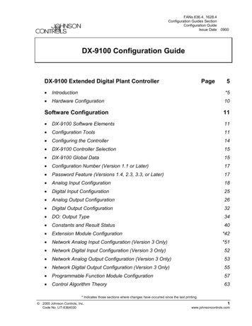
FANs 636.4, 1628.4Configuration Guides SectionConfiguration GuideIssue Date0900DX-9100 Configuration GuideDX-9100 Extended Digital Plant ControllerPage5 Introduction*5 Hardware Configuration10Software Configuration11 DX-9100 Software Elements11 Configuration Tools11 Configuring the Controller14 DX-9100 Controller Selection15 DX-9100 Global Data15 Configuration Number (Version 1.1 or Later)17 Password Feature (Versions 1.4, 2.3, 3.3, or Later)17 Analog Input Configuration18 Digital Input Configuration25 Analog Output Configuration26 Digital Output Configuration32 DO: Output Type34 Constants and Result Status40 Extension Module Configuration*42 Network Analog Input Configuration (Version 3 Only)*51 Network Digital Input Configuration (Version 3 Only)52 Network Analog Output Configuration (Version 3 Only)53 Network Digital Output Configuration (Version 3 Only)55 Programmable Function Module Configuration57 Control Algorithm Theory63* Indicates those sections where changes have occurred since the last printing. 2000 Johnson Controls, Inc.Code No. LIT-63640301www.johnsoncontrols.com
Algorithm 01 - PID Control Module Algorithm 02 - On/Off Control Module78 Algorithm 03 - Heating/Cooling PID Control Module (Dual PID)86 Algorithm 04 - Heating/Cooling On/Off Control Module (Dual On/Off)98 Numerical Calculation and Other Function Module Configurations107 Algorithm 11 - Average107 Algorithm 12 - Minimum Select109 Algorithm 13 - Maximum Select111 Algorithm 14 - Psychrometric Calculation C113 Algorithm 15 - Psychrometric Calculation F116 Algorithm 16 - Line Segment119 Algorithm 17 - Input Selector121 Algorithm 18 - Calculator123 Algorithm 19 - Timer Functions125 Algorithm 20 - Totalization129 Algorithm 21 - Comparator133 Algorithm 22 - Sequencer136 Algorithm 23 - Four Channel Line Segment (Version 1.1 or Later)152 Algorithm 24 - Eight Channel Calculator (Version 1.1 or Later)154 Time Program Functions156 Time Schedule Configuration157 Optimal Start/Stop Configuration161 Programmable Logic Control Configuration174 Dial-up Feature with an NDM Trend Log (Versions 1.4, 2.3, 3.3, or Later) Supervisory Mode Control Settings (General Module) Controller Diagnostics204 Power Up Conditions204 Download/ Upload*206 Calibration Values209* Indicates those sections where changes have occurred since the last printing.2Page Configuration Guides—DX-9100 Configuration Guide65*188192*195
Appendix A: SX Tool Item Description and TablesPage 211 Description of Items211 Item List213 Floating Point Numbers215 EEPROM Items215Appendix B: Item Structure217 General Module Items Structure*217 Programmable Function Module Items Structure223 Analog Input Module Items Structure226 Analog Output Module Items Structure228 Digital Output Module Items Structure229 Extension Module Items Structure230 Time Scheduling Items Structure*236 Optimal Start/Stop Items Structure237 Network Information Module Items Structure238 Network Digital Output Module Items Structure239 Network Analog Output Module Items Structure241 Network Digital Input Module Items Structure243 Network Analog Input Module Items Structure244Appendix C: Programmable Function Module Items247 Algorithm 1 - PID Controller247 Algorithm 2 - On/Off Controller249 Algorithm 3 - Heating/Cooling PID Controller251 Algorithm 4 - Heating/Cooling On/Off Controller253 Algorithm 11 - Average Calculation256 Algorithm 12 - Minimum Selection257 Algorithm 13 - Maximum Selection258 Algorithm 14 - Psychrometric Calculation C259* Indicates those sections where changes have occurred since the last printing.Configuration Guides—DX-9100 Configuration Guide3
Algorithm 15 - Psychrometric Calculation F Algorithm 16 - Line Segment Function261 Algorithm 17 - Input Selector262 Algorithm 18 - Calculator263 Algorithm 19 - Timer Function264 Algorithm 20 - Totalization266 Algorithm 21 - Eight Channel Comparator269 Algorithm 22 - Sequencer271 Algorithm 23 - Four Channel Line Segment Function274 Algorithm 24 - Eight Channel Calculator276260Appendix D: Logic Variables279 Description of Logic Variables279 Logic Variable Tables280Appendix E: Analog Items and Logic Variables for theTrend Log Module* Indicates those sections where changes have occurred since the last printing.4Page Configuration Guides—DX-9100 Configuration Guide*287
DX-9100 Extended Digital PlantControllerIntroductionThis document covers all three versions of the DX-9100 Extended DigitalController, including the DX-912x LONWORKS version. They include:Version 1 – provides up to eight output modules, which are configured togive two analog outputs and six digital outputs (triacs).Version 2 – provides six additional analog output modules, giving a totalof eight analog outputs.Version 3 – the DX-912x LONWORKS version brings peer-to-peercommunication to the feature set of the Version 2 controller,and enhanced alarm reporting capability when used as anintegral part of an Building Automation System (BAS).In this document, BAS is a generic term, which refers to theMetasys Network, Companion , and Facilitator supervisory systems.The specific system names are used when referring to system-specificapplications.The DX-9100 is the ideal digital control solution for multiple chiller orboiler plant control applications, for the Heating, Ventilating, and AirConditioning (HVAC) process of air handling units or for distributedlighting and related electrical equipment control applications. It providesprecise Direct Digital Control (DDC) as well as programmed logic control.In a standalone configuration, the DX-9100 Controller has both thehardware and software flexibility to adapt to the variety of controlprocesses found in its targeted applications. Along with its outstandingcontrol flexibility, the controller can expand its input and output pointcapability by communicating with I/O Extension Modules on an expansionbus, and provides monitoring and control for all connected points via itsbuilt-in Light-Emitting Display (LED). Versions 1 and 2 can communicateon the N2 Bus as well as on the System 91 Bus*, providing point controlto the full BAS Network or to the N30 system or Companion/FacilitatorSystem. The Version 3 controller uses the LONWORKS (Echelon ) N2 Busof the Metasys Control Module (NCM311 or NCM361 in Europe,NCM300 or NCM350 elsewhere) in place of the N2 Bus.*The terms System 91 Bus and Metasys Control Station are not used in North America.Configuration Guides—DX-9100 Configuration Guide5
The DX-9100 has two packaging styles. In Version 1, all terminals forfield wiring are located within the controller enclosure. Versions 2 and 3require a separate field wiring mounting base or cabinet door mountingframe, which enables all field wiring to be completed before the controlleris installed.Figure 1: Version 1 (DX-9100-8154)Figure 2: DX-9100-8454 (Version 2)/DX-912x-8454 (Version 3)with Mounting BaseNote: The mounting base differs for DX-9120 and DX-9121.6Configuration Guides—DX-9100 Configuration Guide
The DX-9100 processes the analog and digital input signals it receives,using twelve multi-purpose programmable function modules, a softwareimplemented Programmable Logic Controller (PLC), time schedulemodules, and optimal start/stop modules; producing the required outputs(depending on the module configuration), operating parameters, andprogrammed logic.Configuration of all versions of the DX-9100 Controller are achieved byusing a Personal Computer (PC) with GX-9100 Graphic ConfigurationSoftware (Version 5 or later) supplied by Johnson Controls. Changes tothe configuration can be made by using an SX-9120 Service Module(Version 3.1 or later).Versions 1 and 2(N2 Bus)The DX-9100 unit (Versions 1 and 2) has two communication links.One is called the N2 Bus or Bus 91 (the term Bus 91 is not used inNorth America) and is used to interface to a supervisory unit. The otherlink is called the XT Bus and is used to expand the DX-9100 input/outputcapability by interfacing up to eight XT-9100 or XTM-905 extensionmodules. The DX-9100 input/output can be extended by up to 64 remoteinput/outputs, analog or digital, depending on the type of the connectedextension modules and XP expansion modules.Point connections are made on XP modules, which are monitored andcontrolled by the XT-9100 or XTM-905 modules. For more details, referto the XT-9100 Technical Bulletin in the System 9100 Manual (FAN 636.4or 1628.4). One XP module can provide either eight analog points oreight digital points. Two XP modules connected to one extension moduleprovides eight analog and eight digital points, or sixteen digital points.Version 1 or 2 of the DX-9100 can be used as a standalone controller or itcan be connected to a BAS through the RS-485 serial communications bus(N2 Bus or Bus 91).Version 3(LONWORKSN2 Bus)Version 3 of the controller (DX-912x-8454) brings peer-to-peercommunication to the feature set of the Version 2 controller, and enhancedalarm reporting capability when used as an integral part of a Metasys BASNetwork.The new communications features are provided by the LONWORKSNetwork, which enables Version 3 controllers to pass data from one toanother and to send event-initiated data to the NCM350 (NCM361 inEurope) Network Control Module, in the BAS. The LONWORKS (Echelon)N2 Bus is used in place of the N2 Bus, and the NCM300 or NCM350(NCM311 or NCM361 in Europe) must be fitted with a LONWORKS(Echelon) driver card.The Version 3 controller retains all the input/output point and controlcapabilities of the Version 2 controller, including the point expansionfeature using extension modules and expansion modules.Configuration Guides—DX-9100 Configuration Guide7
In addition to the Version 2 features, the Version 3 controller has networkinput and output points, which can be configured to transmit and receivedata over the LONWORKS Bus. Each controller may have up to 16 networkanalog input modules, 16 network analog output modules, 8 networkdigital input modules, and 8 network digital output modules. Whilenetwork analog input and output modules each contain a single analogvalue, the network digital input and output modules each contain 16 digitalstates, which are transmitted as a block between controllers. Thetransmission of point data is managed by the LONWORKS Network and isindependent of the supervisory functions of the BAS Network ControlModule (NCM). A network of Version 3 controllers can be installed toshare analog and digital data between controllers on a peer-to-peer basis; aNetwork Control Module is not required unless the network is to besupervised by a BAS.Complex control strategies may now be performed in multiple DX-912xcontrollers without the need for network data exchange routines in asupervisory controller. Applications include the control of multiple,interdependent air handling units, and large hot water or chilled watergenerating plants with components distributed in various locations withinthe building.LONMARK CompatibilityThe Version 3 controller has been approved as a LONMARK device andconforms to the LONMARK specification for network data transmission.RFigure 3: LONMARK TrademarkFurther information about compatibility and interoperability with otherLONMARK devices may be requested from your local Johnson Controlsoffice.8Configuration Guides—DX-9100 Configuration Guide
RelatedInformationRefer to Table 1 for additional information on System 9100 controllers:Table 1: Related InformationDocument TitleCode NumberFANDX-9100 Extended Digital ControllerTechnical BulletinLIT-6364020636.4, 1628.4DX-9100 Configuration GuideLIT-6364030636.4, 1628.4GX-9100 Software Configuration ToolUser’s GuideLIT-6364060636.4, 1628.4LONWORKS N2 Bus Technical BulletinLIT-6364100636.4XT-9100 Technical BulletinLIT-6364040LIT-1628440636.41628.4XT-9100 Configuration GuideLIT-6364050LIT-1628450636.41628.4NDM Configurator Application NoteLIT-6364090LIT-1628490636.41628.4Scheduling Technical BulletinLIT-636116636Point History Technical BulletinLIT-636112636SX-9100 Service Module User’s n Guides—DX-9100 Configuration Guide9
HardwareConfigurationFor full details of the hardware configuration, refer to the DX-9100Extended Digital Controller Technical Bulletin(LIT-6364020) and theXT-9100 Technical Bulletin (LIT-6364040).In summary, the DX-9100 has the following interfaces, inputs, andoutputs:Versions 1 and 2 One N2 Bus (Bus 91) RS-485 port for BAS communicationVersion 3 One LONWORKS N2 Bus for BAS communication and peer-to-peercommunication with other controllers on the same bus (maximum of30 controllers on one LONWORKS Bus)All Versions One XT Bus (RS-485 port) for up to 8 extension modules and amaximum of 64 inputs/outputs One port for service module (SX-9120) communication Eight digital input ports for connection to voltage-free contacts Eight analog input ports; the DX-9100 accepts 0-10 VDC or 0-20 mAsignals from active sensors, or can be connected to Nickel 1000(Johnson Controls or DIN standard), Pt1000, or A99 passiveRTD sensors, as selected via jumpers on the circuit board Six isolated triac digital outputs to switch external 24 VAC circuitswith devices such as actuators or relaysVersion 1 Two analog output ports, 0-10 VDC or 0-20 mA, as selected viajumpers on the circuit board; also, 4-20 mA may be selected byconfigurationVersions 2 and 3 Four analog outputs, 0-10 VDC or 0-20 mA, as selected via jumperson the circuit board; also, 4-20 mA may be selected by configuration Four additional analog outputs, 0-10 VDC only One RS-232-C port for local downloading and uploading softwareconfigurations (N2 Bus protocol)The software configuration determines how these inputs and outputs areused, and their range and application.The DX-9100 must be supplied with a 24 VAC power source. All modelsare suitable for 50 Hz or 60 Hz through software configuration.10Configuration Guides—DX-9100 Configuration Guide
Software ConfigurationDX-9100SoftwareElementsVersion 3 OnlyConfigurationToolsThe DX-9100 is a microprocessor-based programmable controller. It hasthe following software elements: eight analog input modules eight digital input modules two analog output modules in Version 1;eight analog output modules in Versions 2 and 3 six digital output modules up to 64 additional inputs/outputs from up to 8 extension modules twelve programmable function modules with algorithms for controland calculation eight analog constants and 32 digital constants one programmable logic control module with 64 logic result statuses eight time schedule modules two optimal start/stop modules sixteen network analog input modules eight network digital input modules sixteen network analog output modules eight network digital output modulesA user configures the controller using the GX-9100 Graphic SoftwareConfiguration Tool. The SX-9120 Service Module is used to troubleshootand adjust individual parameters. Techniques for both tools are describedin the following sections.For complete documentation on both tools, see the GX-9100 SoftwareConfiguration Tool User’s Guide and the SX-9120 Service Module User’sGuide in FAN 636.4 or 1628.4.Following is a brief description of the main features of the GX-9100Software Configuration Tool. Note that the term, click on, means toposition the cursor on the module or menu and then press the appropriatemouse button to select it.Note: When using the GX Tool, after entering a parameter, always clickon OK to confirm.Configuration Guides—DX-9100 Configuration Guide11
Entering Datainto ModulesTo enter data into a module displayed on the screen of the GX Tool, placethe cursor on the module, click once on the right mouse button and themodule menu will appear:Data.DeleteConnect.F5Disconnect.F4Show SelectedShow User Namesdxcon004Figure 4: Module MenuPlace the cursor on Data and press either mouse button. A Data Windowappears containing all module data. Use the Tab key or mouse to movethe cursor from field to field. To make an entry, move the cursor to theentry field and type in the information. To go to the second page in theData Window (if there is one), click on the Data-2 field. To return to thefirst page, click on OK or Cancel.To exit a window, click on OK to confirm entries, or Cancel to discardthem, while in the first page.Entering ValuesThe following table shows the accuracy that may be lost due to roundingerrors. Numbers with a modulus of greater that 2047 may be rounded up ordown by 0.1% as follows:Table 2: Rounding ErrorsRangeRounding ( /-)2048-409524096-819148192-16383816384-3276716The rounding is due to the external communications bus protocol and doesnot compromise the precision of the internal control processes.12Configuration Guides—DX-9100 Configuration Guide
Entering UserNamesThe Data Window contains User Name and Description entry fields. Up to8 characters may be entered in the User Name field, and the Descriptionfield can have up to 24 characters.The Data Window also contains an Output Tag field for module outputs(i.e., source points), which can be connected to another module as inputs(destinations) and an Input Tag field for module inputs. To enter UserNames for outputs, position the cursor over the Output Tag field and pressthe left mouse button once. To enter User Names for inputs, select theInput Tag field.MakingConnectionsTo expand a module displayed on the screen of the GX Tool, in order toview input/output connections, place the cursor over the module anddouble-click on the left mouse button. Input connections appear in the leftcolumn with @ attached to the Tag Name, and output connections areshown in the right column, except for output modules where allconnections appear in one column. To close a module, place the cursorover the expanded module and double-click on the left mouse button.Connections are made using one of the four methods outlined below.Note that only the first method is referred to later in this guide. An existingconnection must be disconnected before making a new connection. The first method is to expand the source and destination modules bymoving the cursor to each module in turn and double-clicking the leftmouse button. Move the cursor over the desired output of the sourcemodule and the cursor appears as an output arrow. Hold down the leftmouse button and drag the arrow to the desired destination input.When the left mouse button is released, a connection line will bedrawn between the two modules. The second method is to select the source module by positioning thecursor over the module and pressing the left mouse button and thenthe F5 key. A list of the possible source output connections for thatmodule will be shown. Move the cursor to the desired output to selectit (it will appear highlighted) and click on OK (alternatively,double-click on the desired output). To complete the connection,select the destination module by pressing the left mouse button andthen the F5 key. A list of the possible destination inputs for thatmodule will be shown. Select the desired destination from the dialogbox and click on OK (alternatively, double-click on the desireddestination). A connection line will be drawn between thetwo modules.Configuration Guides—DX-9100 Configuration Guide13
Configuring theController The third method is to select the source module by positioning thecursor over it and pressing the right mouse button. The module menuwill appear. Select Connect and a list of possible source outputs forthat module will appear in a dialog box. Move the cursor to thedesired output to select it (it will appear highlighted) and click on OK(alternatively, double-click on the desired output). Then select thedestination module by positioning the cursor on it and pressing theright mouse button. The module menu will appear. Select Connectand a list of possible destination inputs for that module will be shown.Move the cursor to the desired input to select it and click on OK(alternatively, double-click on the desired input). A connection linewill be drawn between the two modules. The fourth method is to go to the destination module data window,move the cursor to a connection field, press the * key on thekeyboard, and the available source output tags will be displayed forselection.Configuring the controller involves: defining characteristics and parameters of the input and outputmodules, the programmable function modules for control andcalculation, the extension modules, and the programmable logiccontrol module defining connections between the modules in order to achieve thedesired sequence of control setting the time scheduling, optimal start/stop, and realtime clockparametersProceed in the following order:1.Select the controller type (Versions 1, 2, or 3).2.Define DX-9100 Global Data under the Edit menu.3.Define Job Information under the Edit menu.4.Define analog and digital input characteristics.5.Define analog and digital output characteristics.6.Define extension module structures and characteristics.7.When applicable, define network inputs and outputs for the Version 3controller (LONWORKS Bus).8.Define programmable function module/algorithm characteristics.9.Define time schedule and exception day settings.10. Define programmable logic control module.14Configuration Guides—DX-9100 Configuration Guide
DX-9100ControllerSelectionVia GX ToolVia the SX ToolSelect the controller version under the Controller menu: DX Version 1.1, 1.2, 1.3, or DX Version 1.4, or DX Version 2.0, 2.1, 2.2, or DX Version 2.3, 2.4 or DX Version 3.0, 3.1, 3.2, or DX Version 3.3 or 3.4The SX Tool will display the controller type when first connected to thecontroller. No user selection is required.DX-9100 GlobalDataSet Power LineFrequency(50 or 60 Hz)Via the GX ToolAt the menu bar at the top of the screen, select Edit-Global Data and a windowappears. Under Frequency, click on 50 or 60 Hz. Then click on OK to confirmthe setting. (To discard an entry, click on Cancel.)Via the SX ToolUnder General Module, set bit X7 of Item DXS1 (RI.32):Set Initialize onPower Up Flag X7 050 Hz power line X7 160 Hz power lineWhen this flag is set to cancel or 1, the override-type Items listed beloware reset after each power up of the controller.When set to maintained or 0, these override-type Items are maintainedthrough the power failure. Shutoff mode request Startup mode request Enable Digital Output (Triac) Supervisory Control Set Digital Output (Triac) On Output Hold mode (Analog and Digital) Programmable Function Module Hold Time Schedule Module Hold modeConfiguration Guides—DX-9100 Configuration Guide15
Via the GX ToolSelect Edit-Global Data. Under Init. on Power Up, click on maintainedor cancelled.Via the SX ToolUnder General Module, set bit X8 of Item DXS1 (RI.32):X8 0 No initialization on power up (commands from BAS maintained)X8 1 Initialization on power up (commands from BAS cancelled)Counter TypeFlagIn the controller, four bytes are reserved for digital input counters andaccumulators in programmable modules. When the DX-9100 is connectedto a BAS, the counter type flag must be set to 0 because the system willonly read 15 bits (maximum reading of 32,767). For BASs that can readfour bytes, or for standalone applications, the flag may be set to 1. Thecounter will then read a maximum value of 9,999,999 and then reset to 0.See Supervisory Mode Control Settings (General Module) further in thisdocument.Via the GX ToolSelect Edit-Global Data. Under Counter Type, click on one of thefollowing: 15-bit (BAS) 4-byteVia the SX ToolUnder General Module, set in bit X4 of Item DXS1 (RS.32):X4 0 Selects 15-bit countersX4 1 Selects 4-bit countersGlobal DataNotesFor temperature unit selection, refer to the Analog Input Configurationsection below.For daylight saving time, refer to the Time Program Functions sectionlater in this document.16Configuration Guides—DX-9100 Configuration Guide
ConfigurationNumber(Version 1.1 orLater)A configuration number may be entered for configuration identificationpurposes. The number will be displayed on the front panel of the controllerduring initialization. The configuration number is also read and used bythe DX LCD Display to identify which of the display configurations in itsdatabase to use for this controller.Via the GX ToolSelect Edit-Global Data. Enter the appropriate number in theUser Config Code field.Via the SX ToolUnder General Module, enter the appropriate number inItem ALG (RI.33).PasswordFeature(Versions 1.4,2.3, 3.3, orLater)The password is used to protect a configuration when loaded into acontroller. Once the password has been downloaded into the controllerwith the configuration, the controller will only allow a subsequentdownload or upload when the password is entered in the Download orUpload dialog box of the GX Software Configuration Tool. The passwordis encrypted by the GX Tool before download.!WARNING:If the password is lost and the user does not haveaccess to the original configuration file that includesthe password, then the controller must be returnedto the supplier or the Johnson Controls factory tohave the memory cleared.IMPORTANT: A password of 0 disables the protection feature.The password feature is only available with firmwareVersions 1.4, 2.3, 3.3, or later. In older versions, thepassword feature was not implemented.Note: The password feature is enabled by an entry in the GX9100.ini fileof the GX Tool. The GX Tool software is delivered without thisentry. Refer to the GX-9100 Software Configuration Tool User’sGuide (LIT-6364060) for details.Via the GX ToolSelect Edit-Global Data. Enter the password (one to four alphanumericcharacters) in the Password field. Enter 0 if the password feature is notrequired. The default password is 0000.Via the SX ToolThe password cannot be accessed via the SX Tool. A GX Tool must beused.Configuration Guides—DX-9100 Configuration Guide17
Analog InputConfigurationThe DX-9100 Controller can accept up to eight analog inputs, which areactive (voltage or current) or passive (RTD). Each analog input is definedand configured by the following parameters: User Name and Description (GX only) Input Signal/Range Measurement Units Enable Square Root Alarm on Unfiltered Value Alarm Limits Filter Time ConstantAI: Input Signaland RangingVia the GX ToolUser Name andDescriptionSelect AIn using the right mouse button. Then select Data in the modulemenu, and enter as appropriate:To assign the input as active or passive, position the cursor on theappropriate box and double-click the left mouse button. Then position thecursor accordingly and click the left mouse button once to select eitherActive or Passive.User Name (maximum 8 characters)Description (maximum 24 characters)For active inputs, at the Type of Active Input field, enter:0 0-10 VDC1 4-20 mA2 0-20 mA18Configuration Guides—DX-9100 Configuration Guide
Each analog input module performs the conversion of the input signal to avariable numeric value expressed in engineering units obtained using thehigh range and low range.High Range(HR) Enter the equivalent number for reading athigh signal input (10 V, 20 mA)Low Range(LR) Enter the reading at low signal input(0 V, 0 mA, 4 mA)AI (PR% / 100) * (HR - LR) LRwhere: PR% analog value in % of physical input signalFor passive inputs at the Type of Passive Input field, enter:1 Ni1000 (Johnson Controls characteristic)2 Ni1000 Extended Temperature Range (Johnson Controlscharacteristic)3 A99 (Johnson Controls characteristic)*4 Pt1000 (DIN characteristic)5 Ni1000 (L. & G. characteristic) (Firmware, Version 1.1 or later)6 Ni1000 (DIN characteristic) (Firmware, Version 1.1 or later)*Note: The North American Johnson Controls silicon sensors(TE-6000 series) have very similar characteristics to theA99 sensor. At 21 C (70 F) and 25 C (77 F) the reference valuesare identical. At -40 C (-40 F), the reading will be 0.8 C (1.5 F)high. At 38 C (100 F), the reading will be 0.3 C (0.5 F) high.For Resistance Temperature Device (RTD) inputs, the range of thedisplayed value is fixed according to the type of sensor. The high/lowrange entries will not have any effect on the actual sensor readout. Theconfigured high and low ranges determine the control range of any controlmodule to which it is connected. (The difference between the High Rangevalue and the Low Range value is equivalent to a proportional bandof 100%.)At the High/Low control range field, enter the required value:High Range (Control) Low Range (Control) Configuration Guides—DX-9100 Configuration Guide19
Via the SX ToolUnder Analog Inputs configure Item AITn (RI.00):(Low Byte)X7 00-10 VoltsX7 10-20 mA, 0-2 V or RTDX8 120% suppression (2-10 V or 4-20 mA)(High Byte)X11 X10 X9 000Active Sensor (Linear)X11 X10 X9 001Ni 1000 RTD Passive Sensor(Johnson Controls)(-45 to 121 C [-50 to 250 F])X11 X10 X9 010Ni 1000 RTD High TemperatureSensor(21 to 288 C [70 to 550 F])X11 X10 X9 011RTD Sensor A99 (Johnson Controls)(-50 to 100 C [-58 to 212 F])X11 X10 X9 100RTD Sensor Platinum 1000 (DIN)(-50 to 200 C [-58 to 392 F])Version 1.1 or LaterX11 X10 X9 101Ni 1000 RTD (L. & G.)(-50 to 150 C [-58 to 302 F])X11 X10 X9 110Ni 1000 RTD (DIN)(-50 to 150 C [-58 to 302 F])For active inputs, the analog input module performs the conversion of theinput signal to a variable numeric value expressed in engineering unitsobtained using the high range at Item HRn (RI.01) and low range at ItemLRn (RI.02).For RTD passive inputs, the range of the displayed value is fixedaccording to the type of sensor. The configured range determines thecontrol range of any control module to which it is connected.AI: MeasurementUnits20Via the GX ToolTo choose between Celsius and Fahrenheit for active and passive sensors,select Edit-Global Data. Under Temperature Units, select Celsius orFahrenheit.Configuration Guides—DX-9100 Configuration Guide
To set the measurement units for active sensors, select the AIn module,and then Data to call up the Data Window. Enter in
Programmable Logic Control Configuration 174 Dial-up Feature with an NDM *188 Trend Log (Versions 1.4, 2.3, 3.3, or Later) 192 Supervisory Mode Control Settings (General Module) *195 Controller Diagnostics 204 Power Up Conditions 204 Download/ Upload *206 Calibration Values 209
