Transcription
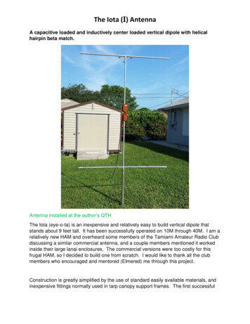
Solar Power for Lunar Pole MissionsRichard Pappa, Geoff Rose, Dave Paddock,and Roger LepschNASA Langley Research CenterHampton, VAJeremiah McNatt and James FincannonNASA Glenn Research CenterCleveland, OHSpace Power Workshop, Torrance, CAApril 3, 2019
Contents NASA’s Return to the Moon plans Advantages of lunar pole sites8charts Water and illumination predictions Lightweight deployable arrays for landers Structural & mechanical Photovoltaics & power Electrostatic dust lifting and adhesion8charts Technology challenges Backup charts 2
Administrator Bridenstine’s Vision “This time we’re going to stay. We’renot going to leave flags and footprintsand then come home.” “We’re making it sustainable so youcan go back and forth regularly withhumans.” “We want the entire architecturebetween here and the Moon to bereusable.” “We want access to the entire Moon.”3
NASA’s Return to the wedLanding CrewedLandingDemo2026For now, NASA’s focus is sustainable explorationand preparation for Mars, not settlement.20284
Notional Configuration ofLunar Gateway and 3-Stage Lander“Human LandingSystem (HLS)” :(A) Transfer stage(B) Descent stage(C) Ascent stageLow Lunar Orbit 50 nmi 2 hr Orbit PeriodNear RectilinearHalo Orbit(A) (B)Perilune Avg:1,817 nmiApolune Avg:38,390 nmi 6.5 day Orbit Period(C)5
Sun Paths on the MoonNorthern SummerNorthern WinterAt the equator, theSun passesdirectly overhead /- 1.5 degsWELatitudeEWWOn the Moon, the Sun moveswestward just 0.5 per hour(1 Lunar day 29.5 Earth days)EAt mid-latitudes,the Sun’s path istilted by latitudedegrees /- 1.5 degsAt the poles, theSun traversesthe horizon /- 1.5 degsNorthern SummerNorthern Winter6
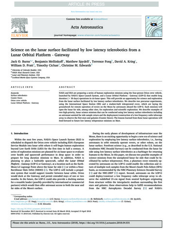
Pros/Cons of Lunar Pole SitesPros: Water ice for life and fuel (H2, O2) is plentiful in polar craters,especially at the South Pole. 74 km2 near the North Pole is illuminated 80% of the time in thesummer, where power can be provided primarily by solar arrays.The South Pole has 26 km2 with 80% illumination. Solar-powered landers, surface operations, and ISRU withminimal energy storage are feasible and sustainable there. Probable site for multi-national “Moon Village” (near South Pole).Cons: Rugged terrain (especially near South Pole) with patches ofsteep slopes, boulders, craters, long shadows. Sun shading and Earth visibility can change dramatically fromthe best case “summer” lunation to the worst case “winter”lunation depending on local elevation and terrain.7
Water Confirmed at Both Poles80 SSouth PoleShuai Li,Aug. 2018North Pole80 N Water ice (yellow) in permanently shadowed craters (cold traps) Temperature: Darker gray colder, Lighter gray warmer “Billions of tons of water ice on the Moon at the poles” – J. Bridenstine8
Illumination Near the Poles is HighlyVariable because of the Rugged Terrainand Low Sun AngleThe best sites for sustained illumination are thehighest points in an area that are not near other high points.9
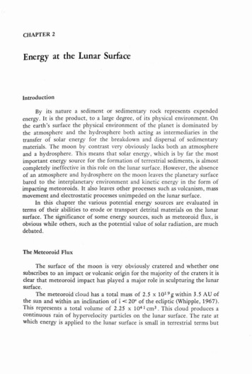
Example Illumination Prediction forMission PlanningSummer QuarterAverageIlluminationusing 240 m/pixelLRO DigitalElevation MapNorth Pole 209 km2: 70% 74 km2: 80% 24 km2: 90% 1.5 km2: 100%85 N0%100%50 kmAdditional predictions inthe Backup charts.10
Solar Array Options for LandersCons ProsBody MountedRotating RigidPanelsLightweightDeployables Simplest Low Risk Used Successfully on Maximum Power OutputPrevious Moon Missions Possibly 100 W/kg 3x Cells Required Operates Hotter No Azimuth Tracking Probably 50 W/kg Adv. Structures/Mech Retraction has Low TRL11
Lightweight Deployable ArraysUltraFlex (NGIS)ROSA(DSS)CTA(NGIS)MMSA (LM)12
Notional Lander with aCompact Telescoping Array (CTA)DeployedStowed13
Notional Lander with anUltraFlex Solar ArrayLocked Down forLanding and LaunchRotated upafter Landing14
Dust Considerations Impact: Covers solar cells: Reduces power and operates hotter Degrades motors, gimbals, hinges, retraction On Apollo, caused some failures after just 75 hrs. Sources: Electrostatic attraction (primary) and friction (secondary) Sticks to even smooth vertical surfaces Electrostatic dust lofting at terminator/polar regions Detected by Surveyors 5, 6, 7, Apollo 17, but not LADEE? Complicated near poles by variable terrain shadows Landing, launching, surface ops will cause the most Surveyor 3 got dusty from Apollo 12 landing 155 m away!15
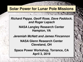
Photovoltaics Demo on CLPS LanderAdvanced photovoltaics and high voltage strings witharc detection and mitigation circuitry.PIs: Jeremiah McNatt and Timothy Peshek (GRC)FrontBackObjectives: Qualify existing technology solar cells on the lunar surface. Also test next-generation and low-cost cells. Quantify plasma environment to improve environmental models. Test high voltage ops in ambient plasma to understand & avoid arcing.Selected for development to potentially be flown as apayload on a commercial lander as early as 2020.16
Technology Challenges forDeployable Arrays on Landers Adaptable Adaptable to multiple landing sites (latitudes) and landers. Reusable Multiple partial or full retractions on reusable lander. Dust Protection from tenacious, highly abrasive dust. Thermal Survivable through temperature extremes. Shadowing Optimal string layout for uncertain terrain shadowing.17
Conclusions Water for life and fuel (H2, O2) is plentiful in polar craters,especially at the South Pole. 74 km2 near the North Pole is illuminated 80% of the time in thesummer, where power can be provided primarily by solar arrays.The South Pole has 26 km2 with 80% illumination. NASA is studying solar power options for reusable landers. A grid of vertical-axis tracking solar arrays could eventuallypower a large polar settlement, e.g.:18
AcknowledgmentsNASA Glenn Research Center:Tom Kerslake, Fred Elliott, Karin Bozak,Lee Mason, Bob CataldoNASA Johnson Space Center:Tim LawrenceNASA Langley Research Center:Dan Mazanek, Gabe Merrill19
Backup20
Lunar Transportation TechnologyDevelopment21
Crewed Lander OptionsNASA Administrator Bridenstine: "We want the entire architecturebetween here and the Moon to all be reusable."NASA expects the Crewed Landers will shuttlebetween the Lunar Gateway and the surface22
Moon is Tilted Just 1.5 from Ecliptic(Negligible Seasonal Effects Except Near Poles)23
Example Illumination Prediction forMission PlanningSummer QuarterAverageIlluminationusing 240 m/pixelLRO DigitalElevation MapSouth Pole 101 km2: 70% 26 km2: 80% 1.1 km2: 100%85 S0%9 km2: 90%100%50 km24
Illumination PredictionsSouth PoleAnnual AverageIlluminationUsing 240 m/pixelLRO DigitalElevation Map Best 3 pixels(Total 0.2 km2): 84% Best 46 pixels(Total 3 km2): 70%25
Rim of the Shackleton Crater –Best Place for a Moon Base? South PoleDiameter: 21 kmDepth: 4.2 km26
Notional Lander with anUltraFlex Solar ArrayLanding Animation – Dusty 27
Lunar Dust is Powdery, Sticky, & Abrasive “Adheres like powdered charcoal to the solesand insides of my boots.” – Neil Armstrong28
Dealing with Lunar Dust Prevention methods: Retract or feather the array prior tolandings, launches, and other ops Sinter or treat lunar surface? Shield the array w/ curtains? Removal methods: Electrodynamic Dust Shield(good for large surfaces such as solar arrays, radiators) Other piezoelectric/electromechanical devices, coatings These methods are not perfect: Dust will probably not come completely off the blanket! Removing dust from mechanisms/joints is harder andthe effects on lubricants and coatings is a concern.Requires robust initial design & development.29
Impact of Dust on Retraction Space arrays are not retractedunless absolutely necessary. Reusing expensive lunar solararrays is desirable and feasible. “Land, deploy, use, retract, launch,and repeat” raises concerns aboutdust on all moving parts, lubricants,and coatings. Retracted solar array must be locked under force to survivelaunch and landing loads, stresses, vibrations and must toleratesome dust in their mechanisms and contacting surfaces. Reusable Hold Down and Release Mechanisms (HDRMs),actuation motors or mechanisms, and springs and hinges mustbe robustly designed to achieve reuse.30
Photovoltaics Environmental considerations: Temperature extremes: -175 C to 125 C, thermal cyclingprofiles are mission and location dependent. Radiation environment: cosmic rays, solar wind, solarflares; degradation expected to be similar to GEO. Cell technologies: Surface spectrum assumed to be AM0 (no atmosphere). SOA technologies (MJ, III-V based) being considered formost near-term missions. Lower-cost technologies could work for short-durationmissions (Si, CIGS, perovskites, single/dual junction cells)Solar cells planned for the lunar surface are high TRLbut largely unproven in this specific environment.31
Radiation environment: cosmic rays, solar wind, solar flares; degradation expected to be similar to GEO. Solar cells planned for the lunar surface are high TRL but largely unproven in this specific environment. Cell technologies: Surface spectrum assumed to be AM0 (no atmosphere). SOA technologies (MJ, III -V based) being considered for