Transcription
TR2007-605, Dartmouth College, Computer ScienceVideo Stabilization and EnhancementHany Farid and Jeffrey B. WoodwardDepartment of Computer ScienceDartmouth CollegeHanover NH 03755AbstractWe describe a simple and computationally efficient approach for video stabilization andenhancement. By combining multiple low-quality video frames, it is possible to extracta high-quality still image. This technique is particularly helpful in identifying people,license plates, etc. from low-quality video surveillance cameras.1
1IntroductionThe poor image quality of many video surveillance cameras effectively renders them useless for thepurposes of identifying a person, a license plate, etc. Under certain conditions, however, it may bepossible to combine multiple video frames for such identification tasks. To this end, we describe asimple and computationally efficient technique for video stabilization and enhancement. The efficacyof this technique is shown on synthetic and real video sequences.2Video StabilizationThe goal of video stabilization is to create a new video sequence where the motion between frames(or parts of a frame) has effectively been removed. To this end, differential motion estimation hasproven highly effective at computing inter-frame motion [3, 2, 5]. We describe one such approachand then describe how a full video sequence is stabilized.We begin by modeling the motion between two sequential frames, f (x, y, t) and f (x, y, t 1) witha 6-parameter affine transform:f (x, y, t) f (m1 x m2 y m5 , m3 x m4 y m6 , t 1),(1)where m1 , m2 , m3 , m4 form the 2 2 affine matrix A and m5 and m6 the translation vector T givenby: m1m3A m2m4 andT m5m6 .(2)With relatively few parameters, the affine model captures a sufficiently rich range of motions suchas translation, scale, and rotation. The basic framework described here can easily be extended toaccommodate higher-order polynomial models that capture a richer set of motions (or even a lowerorder model that models the inter-frame motion with only a translation). In order to estimate theaffine parameters, we define the following quadratic error function to be minimized:XE(m) [f (x, y, t) f (m1 x m2 y m5 , m3 x m4 y m6 , t 1)]2 ,(3)x,y Ωwhere m T ( m1 . . . m6 ) and where Ω denotes a user specified ROI. Since this error function isnon-linear in its unknowns, it cannot be minimized analytically. To simplify the minimization, weapproximate this error function using a first-order truncated Taylor series expansion:E(m) X[f (f (m1 x m2 y m5 x)fx (m3 x m4 y m6 y)fy ft )]2x,y Ω X[ft (m1 x m2 y m5 x)fx (m3 x m4 y m6 y)fy ]2x,y Ω X hi2k cT m (4),x,y Ωwhere, for notational convenience, the spatial/temporal parameters are dropped, and where thescalar k and vector c are given as:(5)k ft xfx yfyT c ( xfxyfxxfy2yfyfxfy ) .(6)
The quadratic error function is now linear in its unknowns, m, and can therefore be minimized analytically by differentiating with respect to m: dE(m) dm X hi2 c k cT m ,(7)Ωsetting the result equal to zero, and solving for m to yield:# 1 ""m XT c cΩ#X(8) ck .ΩThis solution assumes that the first term, a 6 6 matrix, is invertible. This can usually be guaranteedby integrating over a large enough ROI (Ω) with sufficient image content.Central to the above motion estimation are the calculation of the spatial/temporal derivatives.Given a pair of frames f (x, y, t) and f (x, y, t 1), these derivatives are computed as follows:fx (x, y, t) (0.5f (x, y, t) 0.5f (x, y, t 1)) ? d(x) ? p(y)(9)fy (x, y, t) (0.5f (x, y, t) 0.5f (x, y, t 1)) ? p(x) ? d(y)(10)ft (x, y, t) (0.5f (x, y, t) 0.5f (x, y, t 1)) ? p(x) ? p(y),(11)where ? denotes the convolution operator, and d(·) and p(·) are 1-D separable filters:d(x) ( 0.5 0.5 )andp(x) ( 0.50.5 ) ,(12)and where p(y) and d(y) are the same filters oriented vertically instead of horizontally.The required spatial/temporal derivatives have finite support thus fundamentally limiting theamount of motion that can be estimated. A coarse-to-fine scheme is adopted in order to contend withlarger motions [4, 1]. A L-level Gaussian pyramid is built for each frame, f (x, y, t) and f (x, y, t 1).The motion estimated at pyramid level l is used to warp the frame at the next higher level l 1,until the finest level of the pyramid is reached (the full resolution frame at l 1). In so doing, largemotions are estimated at the coarse levels, and are iteratively refined through the pyramid levels.The repeated warping through the pyramid levels can introduce significant blurring and thereforeadversely effect the motion estimation at the higher pyramid levels. This can be avoided by alwaysoperating on the original frame. Specifically, if the estimated motion at pyramid level l is m1 , m2 ,m3 , m4 , m5 , and m6 , then the original frame should be warped with the affine matrix A and thetranslation vector T given by: A m1m3m2m4 andT 2l 1 m52l 1 m6 .(13)As we work through each level of the pyramid, the original frame will have to be repeatedly warpedaccording to the motion estimates at each pyramid level. These individual warps can be accumulatedso that the original frame need only undergo one warp. Specifically, two affine matrices A1 and A2and corresponding translation vectors T 1 and T 2 are combined as follows:A A2 A1T A2 T 1 T 2 ,and(14)which is equivalent to applying A1 and T 1 followed by A2 and T 2 . The warped original frame is thendecomposed into the next required pyramid level, and the process repeated through all pyramidlevels.3
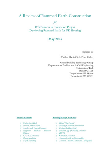
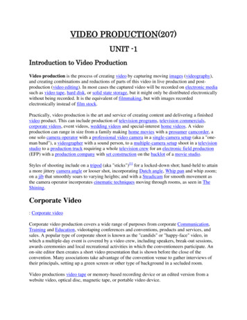
Figure 1: Three of one hundred simulated video sequences undergoing a global affine transformation(every other frame of the 11-frame sequence is shown).To this point, we have described how to estimate the inter-frame motion between two frames.For a video sequence f (x, y, t), t [1, N ], the inter-frame motion is computed between all pairs ofneighboring frames, f (x, y, t) and f (x, y, t 1), for t [2, N ] to yield motion estimates m t . With theROI (Ω in Equation (8)) specified on the first frame, the ROI must be warped on each successive frameto account for the underlying motion between frames. The ROI at time t (t 2) is therefore simplywarped according to the previous frame’s estimated motion. With the motion estimated betweenall pairs of neighboring frames, each frame is warped to align with the last frame of the sequence.Successive warps are combined according to Equation (14). See Appendix A for a complete Matlabimplementation of this video stabilization algorithm.3Video EnhancementOnce stabilized, the video sequence is combined to yield a single high quality image. We assume thatthe corrupting noise on each video frame is identically and independently drawn (iid) from a zeromean distribution. Under this assumption a temporal mean or median filter is the optimal approachto removing the noise – the temporal mean minimizes the L2 norm and the temporal median minimizes the L1 norm between the true and estimated value at each pixel. Specifically, denote f (x, y, t),t [1, N ] as the original video sequence, and fˆ(x, y, t) as the stabilized video. The enhanced frameis estimated by simply computing a pixel-wise mean or median across fˆ(x, y, t). Although typicallycomparable, one temporal filter may give better results than the other depending on the specific noisecharacteristics. See Appendix B for a Matlab implementation.4
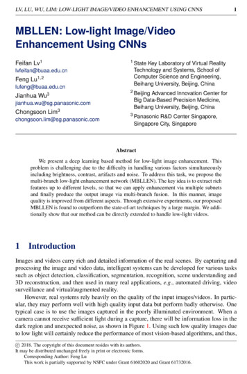
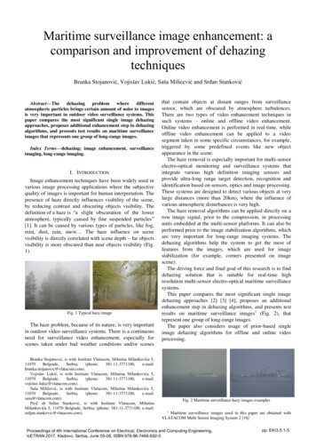
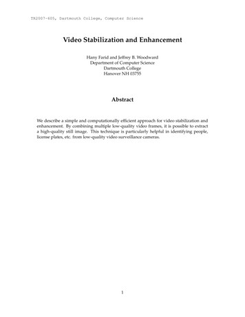
Figure 2: Shown is (a) the average misalignment in pixels as a function of signal to noise ratio (SNR);and (b) the signal to noise ratio of the enhanced image (the red dashed curve denotes the results of thetemporal mean filter, and blue solid curve denotes the results of the temporal median filter).4ResultsTo test the efficacy of the video stabilization algorithm, simulated video sequences were generatedas follows. The first frame was a 256 256 central crop of a grayscale image. The motion betweenframes followed the affine model, Equation (2), where the affine and translation parameters wererandomly generated to yield an average 2-pixel displacement between successive frames. Shownin Figure 1 are three examples of 11-frame sequences (only every other frame is shown). The ROIwas a central 240 240 region. One hundred sequences were generated and stabilized. Prior tostabilization, the average frame to frame displacement was 2.0 pixels. After stabilization, the averagepixel displacement was 0.02 pixels. Visually, little to no motion could be seen in the stabilized video.Since we are interested in enhancing noisy video, it is natural to test the efficacy of the stabilizationin the face of noise. Random zero-mean Gaussian noise, with varying signal to noise ratio (SNR), wasadded to each frame of a video sequence prior to stabilization. The same one hundred sequencesas described above were stabilized. Shown in Figure 2(a) is the average pixel displacement afterstabilization as a function of SNR, and shown in Figure 2(b) is the signal to noise ratio of the enhancedframe. Note that even at very high levels of noise, the stabilization is effective to sub-pixel levels, andthe enhanced frame is of significantly higher signal to noise ratio relative to the original. Shown inFigure 3 are three examples of the final enhanced frames.And lastly, two real video sequences with complex motions were further corrupted with noise,stabilized and enhanced. Shown in Figure 4 is one frame of the original video and the enhancementresults. In these examples, the motion estimation was applied to a grayscale version of each colorframe, and the stabilization and enhancement applied separately to each color channel. The ROI wasa rectangular region encompassing the license plate and face.5
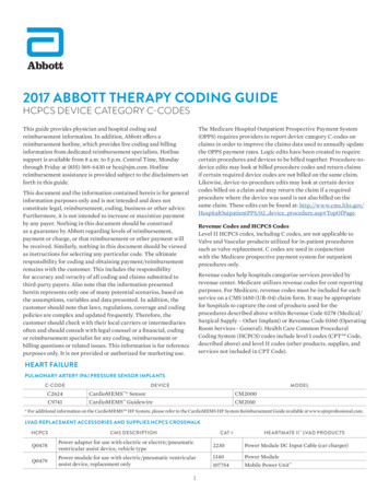
originalnoisemeanmedianFigure 3: Shown is an original frame, this frame plus noise ( 30 dB) and the results of stabilizationand temporal mean and median filtering.5DiscussionWe have described a simple and computationally efficient technique for video stabilization and enhancement. The motion between video frames is modeled as a global affine transform whose parameters are estimated using standard differential motion techniques. A temporal mean or medianfilter is then applied to this stabilized video to yield a single high quality frame. We have shown theeffectiveness of this technique on both synthetically generated and real video. This technique shouldprove useful in enhancing the quality of low-grade video surveillance cameras.6
originalnoisemeanFigure 4: Shown is an original frame, this frame plus noise and the results of stabilization and temporalmean filter. Also shown is a magnified view of the license plate (top) and face (bottom).7
6AcknowledgmentsThis work was supported by a gift from Adobe Systems, Inc., a gift from Microsoft, Inc., a grantfrom the United States Air Force (FA8750-06-C-0011), and by the Institute for Security TechnologyStudies at Dartmouth College under grant 2005-DD-BX-1091 from the Bureau of Justice Assistanceand Award Number 2006-CS-001-000001 from the U.S. Department of Homeland Security. Points ofview or opinions in this document are those of the author and do not represent the official positionor policies of the U.S. Department of Justice, the U.S. Department of Homeland Security, or any othersponsor.References[1] P. Anandan. A computational framework and an algorithm for the measurement of visual motion. International Journal of Computer Vision, 2(3):283–310, 1989.[2] J.L. Barron, D.J. Fleet, and S.S. Beauchemin. Performance of optical flow techniques. InternationalJournal of Computer Vision, 12(1):43–77, Feb. 1994.[3] B.K.P. Horn. Robot Vision. MIT Press, Cambridge, MA, 1986.[4] B.D. Lucas and T. Kanade. An iterative image registration technique with an application to stereovision. In International Joint Conference on Artificial Intelligence, pages 674–679, Vancouver, 1981.[5] E.P. Simoncelli. Handbook of Computer Vision and Applications, chapter Bayesian Multi-scale Differential Optical Flow, pages 397–420. Academic Press, 1999.8
Appendix ABelow is Matlab code for video stabilization. The function videostabilize takes as input: (1) adata structure frames with field im that contains the original video sequence; (2) the number ofGaussian pyramid levels L; and (3) a binary image roi that specifies the region of interest, withvalue of 1 for those pixels to be considered in the motion estimation, and 0 otherwise. It is assumedthat each frame is a grayscale image. The output of this function is a data structure stable withfield im that contains the stabilized video sequence, and a data structure motion with fields A and Tthat contain the estimated affine and translation parameters.% ----------------------%%% STABILIZE VIDEOfunction[ motion, stable ] videostabilize( frames, roi, L )N length( frames );roiorig roi;%%% ESTIMATE PAIRWISE MOTIONAcum [1 0 ; 0 1];Tcum [0 ; 0];stable(1).roi roiorig;for k 1 : N-1[A,T] opticalflow( frames(k 1).im, frames(k).im, roi, L );motion(k).A A;motion(k).T T;[Acum,Tcum] accumulatewarp( Acum, Tcum, A, T );roi warp( roiorig, Acum, Tcum );end%%% STABILIZE TO LAST FRAMEstable(N).im frames(N).im;Acum [1 0 ; 0 1];Tcum [0 ; 0];for k N-1 : -1 : 1[Acum,Tcum] accumulatewarp( Acum, Tcum, motion(k).A, motion(k).T );stable(k).im warp( frames(k).im, Acum, Tcum );end% ----------------------%%% ALIGN TWO FRAMES (f2 to f1)function[ Acum, Tcum ] opticalflow( f1, f2, roi, L )f2orig f2;Acum [1 0 ; 0 1];Tcum [0 ; 0];for k L : -1 : 0%%% DOWN-SAMPLEf1d down( f1, k );f2d down( f2, k );ROI down( roi, k );%%% COMPUTE MOTION[Fx,Fy,Ft] spacetimederiv( f1d, f2d );9
[A,T] computemotion( Fx, Fy, Ft, ROI );T (2ˆk) * T;[Acum,Tcum] accumulatewarp( Acum, Tcum, A, T );%%% WARP ACCORDING TO ESTIMATED MOTIONf2 warp( f2orig, Acum, Tcum );end% ----------------------%%% COMPUTE MOTIONfunction[ A, T ] computemotion( fx, fy, ft, roi )[ydim,xdim] size(fx);[x,y] meshgrid( [1:xdim]-xdim/2, [1:ydim]-ydim/2 );%%% TRIM EDGESfx fx( 3:end-2, 3:end-2 );fy fy( 3:end-2, 3:end-2 );ft ft( 3:end-2, 3:end-2 );roi roi( 3:end-2, 3:end-2 );x x( 3:end-2, 3:end-2 );y y( 3:end-2, 3:end-2 );indxfxxfx find( roi 0 );x(ind); y y(ind);fx(ind); fy fy(ind); ft ft(ind);x.*fx; xfy x.*fy; yfx y.*fx; yfy 4,4)M(5,1)M(5,4)M(6,1)M(6,4) sum( xfxsum( xfxM(1,2);sum( yfxM(1,3);sum( xfyM(1,4);sum( yfyM(1,5);M(4,5);M(1,6);M(4,6);.* xfx ); M(1,2) .* yfy ); M(1,5) M(2,2) .* yfy ); M(2,5) M(3,2) .* yfy ); M(3,5) M(4,2) .* yfy ); M(4,5) M(5,2) M(5,5) M(6,2) M(6,5) k ftb(1) b(3) b(5) xfx yfy;sum( k .* xfx );sum( k .* xfy );sum( k .* fx );sum( xfx .* yfx );sum( xfx .* fx );sum( yfx .* yfx );sum( yfx .* fx );M(2,3);sum( xfy .* fx );M(2,4);sum( yfy .* fx );M(2,5);sum( fx .* fx );M(2,6);M(5,6);b(2) sum( k .* yfx );b(4) sum( k .* yfy );b(6) sum( k .* fy );v inv(M) * b’;A [v(1) v(2) ; v(3) v(4)];T [v(5) ; M(4,6)M(5,3)M(5,6)M(6,3)M(6,6) sum( xfx .* xfy );sum( xfx .* fy );sum( yfx .* xfy );sum( yfx .* fy );sum( xfy .* xfy );sum( xfy .* fy );M(3,4);sum( yfy .* fy );M(3,5);sum( fx .* fy );M(3,6);sum( fy .* fy );
% ----------------------%%% WARP IMAGEfunction[ f2 ] warp( f, A, T )[ydim,xdim] size( f );[xramp,yramp] meshgrid( [1:xdim]-xdim/2, [1:ydim]-ydim/2 );P [xramp(:)’ ; yramp(:)’];P A * P;xramp2 reshape( P(1,:), ydim, xdim ) T(1);yramp2 reshape( P(2,:), ydim, xdim ) T(2);f2 interp2( xramp, yramp, f, xramp2, yramp2, ’bicubic’ ); % warpind find( isnan(f2) );f2(ind) 0;% ----------------------%%% BLUR AND DOWNSAMPLE (L times)function[ f ] down( f, L );blur [1 2 1]/4;for k 1 : Lf conv2( conv2( f, blur, ’same’ ), blur’, ’same’ );f f(1:2:end,1:2:end);end% ----------------------%%% SPACE/TIME DERIVATIVESfunction[ fx, fy, ft ] spacetimederiv( f1, f2 )%%% DERIVATIVE FILTERSpre [0.5 0.5];deriv [0.5 -0.5];%%% SPACE/TIME DERIVATIVESfpt pre(1)*f1 pre(2)*f2; % pre-filter in timefdt deriv(1)*f1 deriv(2)*f2; % differentiate in timefx conv2( conv2( fpt, pre’, ’same’ ), deriv, ’same’ );fy conv2( conv2( fpt, pre, ’same’ ), deriv’, ’same’ );ft conv2( conv2( fdt, pre’, ’same’ ), pre, ’same’ );% ----------------------%%% ACCUMULATE WARPSfunction[ A2, T2 ] accumulatewarp( Acum, Tcum, A, T )A2 A * Acum;T2 A*Tcum T;11
Appendix BBelow is Matlab code for enhancing a stabilized video sequence. The function videoenhance takesas input a data structure stable with field im that contains a stabilized video sequence (the output of videostabilize, Appendix A). The output of this function are two images tempmean andtempmedian that contain the results of temporally filtering the stabilized video.% ----------------------%%% ENHANCE STABILIZED VIDEOfunction[ tempmean, tempmedian ] videoenhance( stable )N length( stable );[ydim,xdim] size( stable(1).im );%%% BUILD A 3-D IMAGE STACK FROM THE INPUT SEQUENCEstack zeros( ydim, xdim, N )for k 1 : Nstack(:,:,k) stable(k).im;end%%% FILTERtempmean mean( stack, 3 );tempmedian median( stack, 3 );12
We describe a simple and computationally efficient approach for video stabilization and enhancement. By combining multiple low-quality video frames, it is possible to extract a high-quality still image. This technique is particularly helpful in identifying people, license plates, etc. from low-quality video surveillance cameras. 1