Transcription
MoDOTTE210.5.P55oDOTL642000---.-/ search, Development and TechnologyUniversity o Missouri-ColumbiaRDT 00-007Slope Stabilization Using RecycledPlastic Pins- ConstructabilityRl 98-007July, 2000
Final ReportRDT00-007Research Investigation 98-007Slope Stabilization Using Recycled Plastic Pins - ConstructabilityPREPARED FORMISSOURI DEPARTMENT OF TRANSPORTATIONRESEARCH, DEVELOPMENT AND TECHNOLOGYJEFFERSON CITY, MISSOURIBY:J. Erik LoehrAssistant Professor of Civil EngineeringJohn. J. BowdersAssociate Professor of Civil EngineeringHani SalimAssistant Professor of Civil EngineeringDepartment of Civil and Environmental EngineeringUniversity of Missouri - ColumbiaDATE SUBMITTED: July, 2000The opinions, findings, and conclusions expressed in this publication are those of the principalinvestigators and the Missouri Department of Transportation: Research, Development andTechnology.They are not necessarily those of the U.S. Department of Transportation, Federal HighwayAdministration. This report does not constitute a standard or regulation.
TECHNICAL REPORT DOCUMENTATION PAGEI. ReportNo.12. Government Accession No.RDT00-0074. Title and SubtitleSlope Stabilization Using Recycled Plastic Pins- Constructability3. Recipient's Catalog No.5. ReportDateJuly20006. Performing Organization CodeUniversity of Missouri -Columbia8. Performing Organization Report No.RDT 00-007 I RI 98-007.10. Work Unit No.7. Author(s)J. Erik Loehr, John J. Bowders, Hani Salim9. Performing Organization Name and AddressUniversity of Missouri- ColumbiaDept. of Civil and Environmental Engineering; E2509 Engineering Building East11. Contract or Grant No.Columbia, MO 65211-220013. Type of Report and Period Covered12. Sponsoring Agency Name and AddressFinal ReportMissouri Department of TransportationResearch, Development and Technology14. Sponsoring Agency CodeP. 0. Box 270-Jefferson City, MO 65102MoDOT15. Supplementary NotesThe investigation was conducted in cooperation with the U.S. Department of Transportation, Federal Highway Administration.16. AbstractA new technology for stabilizing slopes was developed by the Civil & Environmental Engineering Department atthe University of Missouri-Columbia for the Missouri Department of Transportation. The technology uses RecycledPlastic Pins (RPPs) manufactured by pressure-molding recycled polyethylene with a compliment of sawdust and otherby-products. The RPPs were manufactured by a Missouri firm. There are 20 to 30 other manufacturers in the UnitedStates.The constructability of the RPP technology was demonstrated by stabilizing two slides located in an embankmentlocated on Interstate 70 at milepost 62 in Missouri. The embankment had a history of repeated slope failures, each ofwhich was repaired by pushing the soil back in place.For this demonstration, the failed slopes were regraded to their original configuration and reinforced with a total of317 pins (includes both slopes), or RPPs, installed on a 3-foot grid pattern using a mast-mounted vibratory hammersystem. The RPPs were installed in November 1999. The RPPs were driven flush with the ground surface. The rate ofinstallation of the pins averaged approximately 80 feet per hour.Instrumentation was installed on the RPPs and in the slope to monitor performance. Performance monitoring todate, June 2000, shows the slopes to be stable. A longer monitoring period is required before definitive conclusions onthe performance can be made.The unit cost for installation of the RPP stabilization technology at the Emma, MO site was 3.90/ft'- twenty-fivepercent less than for the traditional technique of using rock armor. The RPP technology offers an additional alternativefor stabilization of shallow slope failures. Additional demonstrations and longer performance monitoring periods arewarranted to document the range of applicability and validate the design methodology for the RPP stabilizationtechnology.17. Key WordsSurficial slope failuresSlope stabilizationReinforced slopesRecvcled plastic19. Security Classification (of this report)Unclassified18. Distribution StatementNo restrictions. This document is available to the publicthrough National Technical Information Center, Springfield,Virginia 22161120. Security Classification (of this page)Unclassified21. No. of Pages122. PriceFonn DOTF 1700.7 (06/98)
AcknowledgementsThe authors express their sincerest appreciation to the following individuals and entitiesfor their cooperation and support that assured the success of this project: Pat Carr, The Judy Company, Kansas City Missouri, Kurt DeRuy, Tarnko Composite Products, (formerly DuraBoard), Lamar Missouri, Mike McGrath, Area Engineer, District 2 Missouri Department of Transportation, Tom Fennessey, Sr. Materials Engineer, Soils & Geology Section, MissouriDepartment of Transportation, Mark Virkler, University of Missouri - Columbia, Director of Mid-AmericaTransportation Consortium for MU, Sam Kiger, Chair of Civil & Environmental Engineering, University of Missouri Columbia, The Undergraduate Research Scholars Program, University of Missouri-Columbia,and Mr. David Schelp, Emma Market, Emma, Missouri.
Executive SummaryThe primary objective of the project entitled "Slope Stabilization Using Recycled PlasticPins" was to demonstrate the constructability of a stabilization scheme using recycled plasticpins (RPPs) by stabilizing a single slope at a site representative of MoDOT slope failures. Theselected demonstration site is the southern side of the eastbound entrance ramp embankment toInterstate 70 near Emma Missouri (Milepost 62). Four slide areas have experienced repeatedfailures at the site. Two of the slides were stabilized using the RPP technology. The other twoslides are being used as control sections. The two reinforced slides and one unreinforced slidewere instrumented to measure and document performance. After seven months, all of the slopeshave remained stable. Field .instrumentation monitoring is ongoing to provide more definitivevalidation of the stabilization technique.A limit-state design methodology was developed and used to determine the number,spacing and length of the pins needed to stabilize the slides. The procedure does not account forgroup or interaction effects. Such behavior may increase the effectiveness of the reinforcementbut requires fundamental analyses and testing prior to being incorporated into the design. Criticalparameters identified for design are: depth of sliding surface, pin capacity, and pin spacing.Notable fmdings from preliminary parametric analyses are that soil strength plays a secondaryrole in the stability of RPP reinforced slopes and that improvement in stability of a slope due toreinforcement is similar whether using recycled plastic ("weak" reinforcement) or steel ("strong"reinforcement) members of the same size and spacing.Installation required slightly more than 4 days for driving a total of 317 pins into the twoslides. During the installation process the RPPs were notably very durable under even harddriving conditions. It was found that driving the pins perpendicular to the slope face was lessproblematic than driving them vertically. A mast driving system, one that supports both the RPPand the driving hammer, was much more effective, accurate, and required less skill to operate.In order to maintain peak driving efficiency, a guided (mast-type) driving system is required.Average installation rates ranged from 70 to 100 ftlhour using the mast driving system.A preliminary economic comparison for stabilizing the Emma slides showed costs for theRPP technology ( 3.90/ft2) to be slightly less than estimated costs for traditional rock armor( 5.40/ft2) and many times less than for traditional soil nailing ( 19.00/ft2).An extensive evaluation of the engineering and material properties of the recycled plasticwas performed concurrent with the field demonstration. The recycled plastic was found to havea peak tensile strength ranging from 1.3 ksi to 1.8 ksi and a peak compressive strength of 3.0 ksi.Peak bending moments were 1.0 kip-ft for a nominal 4-inch by 4-inch cross-section. Coupons ofthe recycled plastic were exposed for a period of up to a year in an acidic (pH 5) solution,ultraviolet light, tap water, kerosene, and freeze/thaw environments. Only the keroseneenvironment caused a notable reduction in the strength of the material.The results of two years of creep testing were used in an Arrhenius model to predict theimpact of sustained loading on the RPPs. The findings showed that current field loadings wouldnot cause failure of the RPPs for 1000 years. These results diminish concerns about creepdeformations for the slope stability application of RPPs.Stabilizing slopes with recycled plastic pins shows much promise for an alternative repairmethod for shallow slope failures. In order to achieve wide ranging acceptance of thetechnology, several tasks remain including: demonstrating the applicability or range ofapplications of the technology, validating the design procedure through performance monitoringdata, and more completely assessing the economics of the technique.ii
Table of ContentsAcknowledgements . iExecutive Summary . iiTable of Contents . .iiiList of Figures . ivList of Tables . vIntroduction . IDemonstration Site . ISite Investigation and Laboratory Testing . IInstallation and Constructability . 3Economics . 7Future Enhancements to Driving System . 7Instrumentation and Monitoring . 8Development of Preliminary Design Procedure . 13Engineering and Material Properties . 17Tension, Compression, Shear and Bending . 17Interface Friction . 18Bending Creep . 19Conclusions . 24Constructability: . 24Material Properties: . 25Design Methodology: . 25Preliminary Economic Comparison: . 25Recommendations . 25References . 27Principal Investigator and Project Members . 28Appendix A- Emma Site Boring Logs and Subsurface Cross-sections . 29Appendix B - Consolidated-Undrained Triaxial Test Results . .48Appendix C - Measured Bending Moments for Instrumented Pins . 51Appendix D - Slope Inclinometer Data . 57Appendix E - Recycled Plastic Material Properties from Exposure Tests . 63Appendix F - Bending Creep Test Data and Arrhenius Modeling Calculations . 67iii
Figure 1.Figure 2.Figure 3.Figure 4.Figure 5.Figure 6.Figure 7.Figure 8.Figure 9.Figure 10.Figure 11.Figure 12.Figure 13.Figure 14.Figure 15.Figure 16.Figure 17.Figure 18.List of FiguresPlan view of the demonstration site located north of Emma, Missouri at I-70Milepost 62, with the four slope failures designated as S 1 through S4 . 2Layout of plastic pins at the Emma demonstration site for slide areas S 1 and S2showing the varying penetration depths . 4Initial equipment used for installation of recycled plastic pins at the Emma,Missouri demonstration site. 5Crawler mounted drilling rig used for installation of recycled plastic pins at theEmma, Missouri demonstration site. 6Plan view of location of instrumentation for Slide S 1 Emma Missouri . 8Plan view of location of instrumentation for Slide S2 Emma Missouri . 9Plan view of location of instrumentation for Slide S3 Emma Missouri . 9RPP showing the location of resistance strain gages for measuring strains on thepins in the field . 10Typical strain versus depth along instrumented Pin A (mid-slope, slope S2), as of17 April2000, located at the Emma, Missouri demonstration site. Note: 1000microstrains is equal to 0.1 percent strain . 11Measured bending moment as a function of depth in Pin B, Emma Missouridemonstration site - 17 April 2000. 12Precipitation data collected from Sweet Springs Missouri weather observationstation 3.5 miles east of the Emma Missouri demonstration site. Note: Pins wereinstalled in November 1999. 12Distribution of limiting lateral resistance per unit length of slope: (a) limitingresistance for the soil, pins, and anchorage and (b) composite limiting resistance.Data shown are for 4-in. x 4-in. x 8-ft. pins on 3-ft. spacing in soil with c O, ? 21degrees, and 7 11 0 pcf. 14Method for computing the limiting pin resistance as a function of depth of sliding:(a) moment distributions due to limiting soil pressure and reduced lateral pressureand (b) limiting soil pressure and reduced limiting soil pressure. 16Elevation view of tilt table test for interface friction between Emma soil and RPPs.The contact area between the soil and the RPPs was 95 square inches (600 cm2 ) 19Setup for testing creep behavior of recycled plastic pins under bending loads. L was20 inches and the pin cross-section was 2 in. x 2 in . 20Deflection versus time response for RPP loaded with a 50 Lb at the free end of asimple cantilever (Figure 15) under various temperatures from 70 to 176 degrees.With the exception of the specimens at 70 degrees, all specimens failed at the finaldata point. 21Typical Arrhenius plot For bending creep test on 2in.x2in.x24in. RPP loaded as acantilever with a 50 Lb weight at the unsupported end. Plots for other loadingconditions are included in the Appendix F . 22Method for estimating time to failure resulting from bending creep of RPP . 23iv
Table 1.Table 2.Table 3.Table 4.Table 5.Table6.Table 7.List of TablesGeotechnical index properties for selected samples from the Emma site. 3Properties of samples for consolidated-undrained type triaxial tests . 3Summary of the penetration and installation rates for mast-mounted hammer onslope failures S 1 and S2. 6Cost comparison for alternative slope stabilization methods . 7Summary of tension, compression, shear and bending test results on recycled plasticmaterial used in the RPPs . 17Summary of tension and compression properties of recycled plastic materialsubjected to various exposure environments . 18Conditions and results of the creep bending tests on the RPPs . 22v
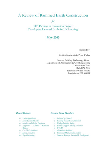
IntroductionThe primary objective for the project entitled "Slope Stabilization Using Recycled PlasticPins" was to demonstrate the constructability of stabilization schemes using recycled plastic pins(RPPs) by stabilizing a single slope at a site representative of Missouri Department ofTransportation (MoDOT) slope failures. Secondary objectives of the project included:evaluating basic material and engineering properties of recycled plastic pins when subjected tovarious potentially deleterious environments; development and evaluation of potential drivingequipment; development of a preliminary design procedure; and initiation of an instrumentationand monitoring program for evaluating the effectiveness of the RPP stabilization scheme. Theactivities and findings of the project are presented in this report Emphasis is given toconstructability of the recycled plastic pin stabilization method.Demonstration SiteDemonstration site #1 was selected in May 1999. The site is located on the eastboundentrance ramp to Interstate 70 at Emma, Missouri (milepost 62). Four general slide areas wereobserved in the embankment just prior to the field demonstration as shown in Figure 1. Threeslide areas, denoted Sl, S2, and S3, are located along the south side of the embankment with anadditional slide, denoted S4, on the north side of the embankment. Information acquired fromlocal maintenance personnel indicated that the Emma site slopes had repeatedly failed over aperiod of a decade or more with failures occurring as frequently as several times each year.Previous slope repair activities included simple regrading of the slopes to their originalconfiguration as well as dumping of concrete rubble over the crest of the slope. All previousstabilizing measures proved unsuccessful. Slide areas S 1 and S2 were selected as test areas forinstallation of RPPs; slide areas S3 and S4 are being used as control sections. The embankmentheight is nominally 23-ft. (7-m) and the slope varies from 2.5H: 1V to 2H: 1V.Site Investigation and Laboratory TestingThe Emma site was drilled and sampled in June 1999 by MoDOT drilling personnel withassistance from University of Missouri - Columbia (MU) researchers. Undisturbed soil sampleswere recovered in 3-inch diameter Shelby tubes. The samples were extruded from the tubes inthe field, wrapped in foil and sealed using hot wax. Samples were then transported to MUGeotechnical Engineering laboratories for testing. Index properties were performed on selectedsamples throughout the site and consolidated-undrained triaxial tests (with pore water pressuremeasurements) were performed on specimens from the suspected shear zone.The site soils were found to be a mixture of lean to fat clays with water contents rangingfrom 15 to 30 percent and averaging about 24 percent (Appendix A). The soils ranged from softto stiff. The average liquid limit was 50 and plasticity index was 28 (Table 1) and the soilsclassified as low plasticity and high plasticity clays. Boring logs and estimated subsurface crosssections are provided in Appendix A.Observation of the site conditions and the existing failures at the site indicated that theshear zone was likely to be in the fat clay layer. Specimens for shear strength testing wereselected from the suspected shear zone (Table 2). Specimens were trimmed to a diameter of 1.5inches and a height of 3.0 inches from the 3-inch diameter Shelby tube samples. ConsolidatedI
undrained triaxial tests were performed to determine the effective shear strength parameters(c and ). The specimens were backpressure saturated to degrees of saturation above 95percent, consolidated to effective stresses of 8 psi and 20 psi respectively, and then sheared at arate of 3.9 x 10·5 in/min (0.001 rnrnlmin). The resulting data (stress difference vs. axial strainand modified Mohr-Coulomb diagram) are provided in Appendix B. The measured effectivefriction angle was 15 degrees and the effective cohesion was 275 psf.N On RampToe SlopeTee SlopeToe SlopeAccessFigure 1. Plan view of the demonstration site located north of Emma, Missouriat 1-70 Milepost 62, with the four slope failures designated as S 1through S4.The shear strength data was used for analyses of the stability of the slopes at the Emmasite. The effective friction angle was held constant (15 degrees) and a search was performed forthe failure surface with a factor of safety of 1.0 by varying the effective cohesion. A failuresurface with a maximum depth of 8 feet was determined for effective stress strength parametersof friction angle at 15 degrees and cohesion at 50 psf. While the cohesion observed from backanalyses is not identical to that measured on the test specimens, it is in reasonable agreement.Observation of the previous slides at the site indicates that the deepest part of the failure surfacecould be about 8 feet below the surface. It is also noted that the embankment soils are stratifiedand heterogeneous in nature ranging from low to high plasticity. The strength is likely to varysimilarly. Thus, while the laboratory measured strengths are likely to be from the slide shearzone, they may not be representative of the strengths everywhere along the sliding surface, butare concluded to be reasonably representative of the soils at the Emma site.2
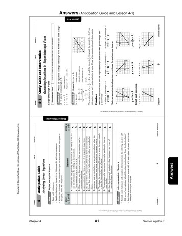
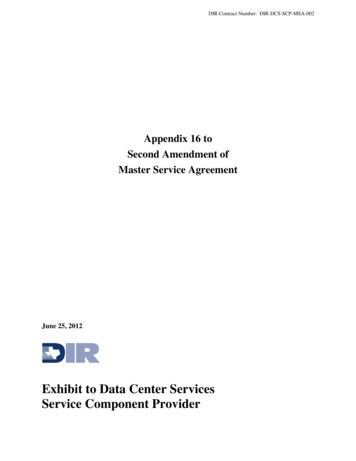
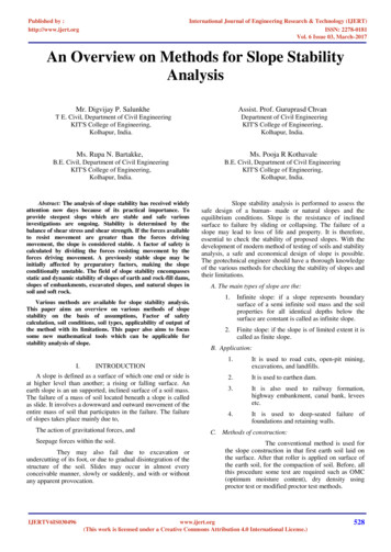
Table I.Geotechnical index properties for selected samples from the Emmasite.BoringLocationMU17MU 16MU15MU12MU12MU PlasticLimit(%) Limit(%)Average Table 5usesClass.CLCLCHCHCLCHCHMLCLCHCH28Properties of samples for consolidated-undrained type triaxial 57523949565650PlasticIndexMU12MU122.5-52.5-5Dry 5EffectiveFrictionAngle(0)15Installation and ConstructabilityA total of 317 RPPs were installed in slides SI and S2 during October and November1999. The pins were installed in a 3-ft (0.91-m) staggered grid with every other row offset by1.5-ft (0.46-m) (Figure 2). Pins were driven perpendicular to the face of the slope in slide Sl andvertically in slide S2. Not all of the RPPs could be driven to the full 8-ft (2.4-m) length due tothe presence of concrete rubble from previous repair attempts. Actual installed lengths areshown in Figure 2. Conditions at the site were generally dry throughout construction allowingfor maximum traction and maneuverability of the driving equipment.Pin installation activities at the field demonstration site were initiated in October 1999.The initial installation equipment used at the site consisted of an Okada OKB 305 1250 ft-lb(1695 N-m) energy class hydraulic hammer mounted on a Case 580 backhoe (Figure 3). Thisequipment proved unacceptable for several reasons. The rubber-tired backhoe was difficult tomaneuver on the slope and caused excessive rutting while trying to reach the top of the slope.Maintaining a fixed position during driving also proved difficult with the backhoe tending toslide down slope even with the outriggers placed, thereby further damaging the slope and makingdriving pins with the correct alignment and placement extremely difficult. The averagepenetration rate obtained using this equipment was 2.3-ft/min (0.7-rnlmin), which wassignificantly less than that obtained during field driving trials held in March 1999. In addition,play in the backhoe boom and the inability to maintain precise alignment of the hammer and pin3
during driving resulted in an excessive number of pins being broken during installation (22broken of 45 attempts). Set up time between installation of pins was also excessive due todifficulty in navigating on the slope and the need to constantly reposition the equipment. As aresult of these problems, the rate of installation (including time for set up and repositioning)averaged only 32.8-ftlhr (10-mlhr). This rate was deemed unacceptable and installation washalted.Crest of Slopev v v v v v v v v v0v v vv v v v v v v v v v v v v vc v v v v v v v v v v v v vvvvvvvvvvvvvvvvvvvvvvvvvvvvvvV V V V V G G G G G G G G G0 0 0 0 v 0 0 0 0 0 0 00 0 0 0 0 0 0 0 0 0 0(a)0Slide S1o Penetration 0 to 2 fto Penetration 3 to 5 ftv Penetration 6 to 8ftSlide AreaS 1 -Pins installed perpendicular to face of slopeCrest of Slopevvvvvvvvvvvvvvvvvvvv v v v v v v v v v vV V D V V V V V V V V V V0Slide S2v v v v v v v v v v v vmv v v v v v v v v v v v vv v v v v v v v v v v v vvvvvvvvvvvvvvv(b)-------o Penetration 0 to 2 fto Penetration 3 to 5 ftv Penetration 6 to 8 ftSlide Area S2 - Pins installed verticallyFigure 2. Layout of plastic pins at the Emma demonstration site for slide areasS 1 and S2 showing the varying penetration depths.4
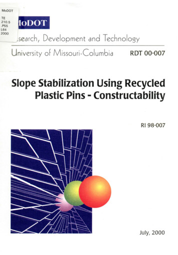
Figure 3. Initial equipment used for installation of recycled plastic pins at theEmma, Missouri demonstration site.Installation at the field demonstration site resumed in early November 1999 using aDavey-Kent DK IOOB crawler mounted drilling rig (Figure 4) supplied by the Judy Company ofKansas City, Kansas. The rig is equipped with a mast capable of 50-degree tilt from verticalforward, 105-degree tilt backward, and side-to-side tilt of 32-degrees from vertical. This rigoffered numerous advantages over previously used equipment. The drilling mast ensured thatthe hammer and pin remained aligned during driving without requiring any movement of thechassis. In addition, the crawler-mounted rig was much easier to maneuver on the slope therebyreducing set up time between pins. The rig was equipped with a Krupp HB28A hydraulichammer drill attached to the mast providing a maximum of 295 ft-lbs (400 N-m) of energy at amaximum frequency of 1800 blows/min. The hammer energy is further augmented by apush/pull of 18,000-lbs (80 kN) supplied by the drill mast.Penetration rates (not including set up time) and installation rates (including set up time)measured during installation using the mast-mounted system are summarized in Table 3. Themast-mounted hammer clearly outperformed all previous installation equipment that wasevaluated. Penetration rates for pins driven perpendicular to the slope reached 10-ft/min (3.0m/min) and averaged 5.2-ftlmin (1.6-m/min). Penetration rates for pins driven vertically wereonly slightly lower reaching a maximum of 9.6-ftlmin (2.9-m/min) and averaging 4.1-ft/min( 1.3-m/min). Installation rates were also dramatically higher than observed previously becauseof reduced set up times reaching a maximum of 124.0-ftlhour (37.8-mlhour) at peak production.The average installation rate for installation of all pins was 80-ft/hour (25-m/hour). Installationrates generally increased during installation of pins for each slide as experience was developedindicating that installation rates for future installations may be closer to the maximum ratesachieved for the field demonstration.5
Figure 4. Crawler mounted drilling rig used for installation of recycled plasticpins at the Emma, Missouri demonstration site.Table 3.Average RateMaximum RateMinimum RateSummary of the penetration and installation rates for mast-mountedhammer on slope failures Sl and S2.Slide S1(Perpendicular Installation)Penetration RateInstallation Rateft/min (mlmin)ftJhr (mlhr)5.2 (1.6)96.0 (29.3)10.0 (3.1)124.0 (37.8)0.1 (0.1)59.0 (18.0)Slide S2(Vertical Installation)Penetration RateInstallation Rateft/min (rnlmin)ftJhr (mlhr)4.1 (1.2)68.0 (20.7)9.6 (2.9)98.0 (29.9)0.5 (0.2)33.0 (10.1)Limitations of the Davey-Kent drilling rig necessitated that pins installed in a verticalalignment were driven with the rig being backed up the slope. While not critical, this feature didresult in slightly lower installation rates for pins driven vertically as compared to pins drivenperpendicular to the
The unit cost for installation of the RPP stabilization technology at the Emma, MO site was 3.90/ft'-twenty-five percent less than for the traditional technique of using rock armor. The RPP technology offers an additional alternative for stabilization of shallow slope failures. Additional demonstrations and longer performance monitoring .