Transcription
Biometric Attendance system Using R-305Sensor and Arduino UnoA Thesis report submitted in partial fulfillment of the requirementsfor the award of the degree inMaster of Technology (Dual Degree)in“VLSI Design and Embedded Systems”BySahil Suhag(Roll No. : 711EC2128)May, 2016Under the guidance ofProf. A.K SwainDepartment of Electronics and Communication EngineeringNational Institute of TechnologyRourkela-769008
DEPARTMENT OF ELECTRONICS ANDCOMMUNICATION ENGINEERINGNATIONAL INSTITUTE OF TECHNOLOGY, ROURKELAODISHA, INDIA -769008CERTIFICATEThis is to certify that the thesis entitled “Biometric Attendance system”, submitted bySahilSuhag (Roll No. 711EC2128) in partial fulfillment of the requirements for the award ofMaster of Technology (Dual Degree) in VLSI Design and Embedded Systemsduringsession 2015-2016 at National Institute of Technology, Rourkela.The candidate has fulfilled all the prescribed requirements. The Thesis is anauthenticallymade, based on the candidates’ own effort and the implementation of his work.To my knowledge and understanding, this thesis is up to the standard required for the awardof a Bachelor of Technology Degree in Electronics and Communication Engineering andMaster of Technology (Dual Degree) in VLSI Design and Embedded Systems.Place: RourkelaProf. A.K SwainAssistant ProfessorDepartment of Electronics and Communication EngineeringNational Institute of TechnologyRourkela -769008
ACKNOWLEDGEMENTSI express my profound gratitude and indebtedness to Prof. A.K.Swain for giving me thepresent project topic and for his intellectual guidance, constructive criticism, inspiring me tofurther the scope of the project and valuable suggestions throughout the project work. Hegranted me relative freedom in deciding the course of action, providing valuable assistancewherever required.I am also grateful to Kamal Kumar (Dept. of Computer Science and Engg.) for his help in theprogramming aspect of the project. All thought out the project his help in optimizing the codeand error solving was very valuable.I would also like to show my gratitude to Ratnakar Vijay (Dept. of Electronics and Comm.Engg.) for his help in the construction of the hardware.I’m also thankful to the Dept. of Electronics and Communication Engineering NIT, Rourkelafor their material support and making the facilities available for the project work.Sahil SuhagRoll No. 711EC2128
ContentsABSTRACT . 11 INTRODUCTION . 51.1 Problem Statement . 51.2 Motivation. 51.3 Use of Biometrics . 51.4 What is finger print? . 61.5 Why use finger prints? . 71.6 Attendance management system using finger print recognition . 71.7 Organization Of Thesis . 82 ARDUINO UNO . 102.1 The Arduino Company and their Product . 102.1.1 Software . 102.2 The UNO Board . 112.2.3 Communication . 122.2.1 MEMORY . 132.2.2 PINS . 132.2.4 The Fail Safe: . 142.3ATMEGA328P PROCESSOR . 153R-305 FINGERPRINT SCAN MODULE . 183.1R-305 . 183.2 Buffer . 193.3 Hardware connection. 193.4 Communication Protocol . 204. INTERFACING. 234.1 Interfacing LCD with Arduino Uno . 234.2 Interfacing R-305 with Arduino Uno . 244.3 Interfacing the command buttons . 244.4 Connection With Arduino . 245 BIOMETRIC SYSTEM SOFTWARE ARCHITECTURE . 275.1 Flowchart . 27
5.2 Subroutines . 285.2.1 SCAN PRINT . 295.2.2 STORE PRINT . 295.2.3 LOAD PRINT . 305.2.4 MATCH PRINT. 305.3 Routines . 315.3.1 ADD FINGERPRINT. 315.3.2 DELETE FINGERPRINT . 325.2.3 SCAN FINGERPRINT . 326 CONCLUSION AND FUTURE SCOPE OF THE PROJECT. 346.1 Conclusion . 346.2 Future Scope of the Project . 34REFERENCES . 36
ABSTRACTEvery organization, be an educational institute or organization public or private, it has tomaintain accurate records of attendance of students or staff for effective working oforganization. As time has shown, both private and public sectors face high level ofmismanagement due to false records and impersonations. Employers and officials areconcerned over employee absenteeism in their human resources and the problems inmaintaining records of student attendance during lecture periods. Finger prints are thepatterns of ridges and valleys on everyone’s finger tips. They can be used as a type ofbiometric identification which, like all personal features, are unique to a person and do notchange in the person’s lifetime. An attendance system based on fingerprint technology,suitable to be used in a university environment, is presented in this thesis. The finger printbased attendance system was implemented with Arduino Uno Microcontroller, R-305fingerprint sensor and programmed in C using Arduino IDE. It comprises of twoprocesses; enrollment and authentication. During enrollment, the finger print of the user iscaptured and its unique defining features extracted to be stored in the flash memory alongwith the other users identities as a template. Minutiae points, the unique feature, are extractedusing a method which extracts the ridge’s endings and bifurcation. During authentication, theuser’s fingerprint is scanned to be stored in one of the two buffers and the extracted featurescompared with the template which is loaded to the other buffer to compare the match beforeattendance is verified. The experimental result exhibits that the system developed is highlyefficient in verifying fingerprint with a high level of accuracy.Page 1
LIST OF FIGURESFigure No.Figure TitlePage No.Figure 1 Minutia Points . 14Figure 2 AnArduino Uno with its Different Parts Labeled.20Figure 3 The ATmega328P Microcontroller .24Figure 4 A R-305 Fingerprint Module .26Figure 5 Pin Numbering of the two Interfaces.28Figure 6 Block Diagram of LCD Pin Connection .31Figure 7 Block Diagram Showing the Connection of Pins of the System .33Figure 8 Flowchart Showing the Execution of the Program.35Page 2
LIST OF TABLESTable No.Table TitlePage No.Table 1Specifications of Arduino Uno . 21Table 2 Specification of R-305 Fingerprint Module. 27Table 3 Pins Names and Function . 28Table 4 Definition of Data Package . 29Page 3
CHAPTER 1INTRODUCTION Motivation Organization of thesis Page 4
1 INTRODUCTION1.1 Problem StatementDesigning and implementing a student attendance verification system based on finger printrecognition and is capable to manages records for attendance in classrooms, laboratoriesseminars etc. in institute like NIT Rourkela.1.2 MotivationMaintaining a record for employee attendance has been in practice for a long time. Over theyears the system to maintain these records has been made more efficient with theintroduction of various technologies. Designing an improved attendance management systemfor students so that records can be maintained with ease, transparency and accuracy was animportant motivating factor behind this project. The accuracy of attendance records wouldbe improved as it will eliminate the hassles of roll calling, where a person physicallyobserves and verifies attendance, and therefore will be crucial in saving time of both – thestudents and the teachers. Various image processing techniques to recognize fingerprintpatterns are available. Today in terms of technology they are very advanced and hence veryprecise. Hence a fast and accurate attendance system, free from the possibility ofimpersonation is designed.1.3 Use of BiometricsBiometric Identification based systems are in wide use for the purpose of uniquely singlingPage 5
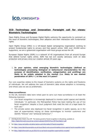
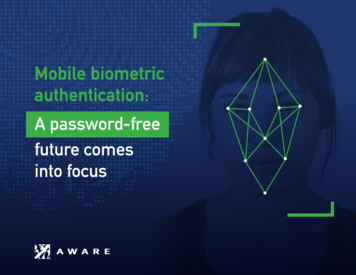
out human beings basically to identify and verify them. There are alot of biometric basedsystems like facial feature recognition, voice recognition, eye’s iris recognition, fingerprintrecognition, palm recognition etc. In this project, we have utilized a finger print recognitionsystem. Such biometric systems can also find usage to provide identity access control. Hencethe use of biometric fingerprint recognition in a student attendance management system is awell trodden path and a reliable approach.Figure 1. Minutia Points1.4 What is finger print?The intricate pattern of ridges and valleys on the surface of a fingertip is called a fingerprint.The ridges are described as the portion of the print which protrudes out and valley is thesunken area between them. The minutiae points are where the ridges end or are split. Theminutiae pattern of each finger, like all other personal features, are unique to a person and donot change in the person’s lifetime. When a ridge curve terminates or ends this is defined asa ridge ending. Where as when a ridge separates from a single path into two forming a Yjunction, the split is defined as a bifurcation. Figure 1 displays a ridge ending and abifurcation. In this example, the dark coloured portion corresponds to the ridges, and the paleportion corresponds to the valleys. When a machine or a human fingerprint expertdetermines whether two given fingerprints belong to the same finger, the degree of matchbetween two minutiae pattern is one of the most detrimental factors. Thanks to the similarityin the way a human finger print expert determines unique matches and compactness of thePage 6
size templates, the minutiae-based fingerprint matching technique is the most widely studiedmatching method.1.5 Why use finger prints?At the present level of development fingerprints have been proven to be the easiest andfastest method for biometric identification. They are secure to use, unique for every personand do not change in a person’s lifetime. Besides these, utilization of fingerprint recognitionsystem is relatively cheap, easy to understand and to put into practice and is accurate tosatisfy the purpose. Fingerprint based recognition systems have been put to wide use in bothforensic and civilian applications. In comparison with other available biometrics featurematching systems, fingerprint-based biometrics is the most developed technique and holdsthe largest market shares. As these systems have been optimized over the years, not only is itfaster than other techniques but the amount of energy consumed by such systems is also less.1.6 Attendance management system using finger print recognitionMaintaining attendance records of students of an institution as large as ours is a tedious task.It takes both time and paper. To change all work regarding attendance to an automatedsystem and on-line, I have built an attendance recording system which can be installed in aninstitute. This project uses a finger print scanning module(R-305) interfaced with amicrocontroller (Arduino Uno). This fingerprint identification system uses existingtechniques in fingerprint recognition and matching.Page 7
1.7 Organization of ThesisChapter 1: This section has an introduction and the organization of thesisChapter 2: This chapter gives information regarding Arduino Uno microcontroller. Thememory of the device, input/ output pins and other hardware information is described. Thefunctioning of ATmega328P microcontroller used in Arduino Uno is also given.Chapter 3: This chapter deals with the R-305 fingerprint module. All specifications aboutthe device are mentioned. Its communication protocol is also described.Chapter 4: This chapter describes the interfacing of various devices to the Arduino Uno,namely the LCD, the R-305 module and the four command buttons.Chapter 5: This chapter explains the working of the software that runs our system. Howvarious routines and subroutines are executed is also described.Chapter 6: This chapter gives the conclusion and the scope of future developments withregard to this project.Chapter 7: This chapter states the references utilized to accomplish this project work.Page 8
CHAPTER 2ARDUINO UNO Arduino Uno ATmega328PProcessor Page 9
2 ARDUINO UNO2.1 The Arduino Company and their ProductArduino is an Italy based software and hardware company and user community that designsand manufactures computer open-source hardware and software. It basically producesmicrocontroller-based kits for the purpose of building practical digital devices andinteractive projects that are capable of sensing and controlling physical devices. Firstintroduced in 2005, the Arduino aimed to provide a low cost, easy way for amateurs andskilled technicians to create devices that interact with their environment and surroundingsusing sensors and actuators. Commercially available Arduino MCU Boards come inpreassembled form, or as do-it-without anyone's help kits. The hardware design plans too arefreely available, allowing the Arduino MCU boards to be made by any and everyone. In2013, Adafruit Industries assessed that around 700,000 official boards were in its client’shands.2.1.1 SoftwareThe Arduino company provides the Arduino integrated development environment (IDE), thisis a multiple-platform application developed in Java. To let electronics enthusiasts getfamiliarized with software development, its designed to introduce them to programming. Itcontains a code editor having features such as syntax highlighting, brace matching, andautomatic indentation, and provides quick and simple one-click operations to compile andthen upload programs on to an Arduino MCU board. A program written on the ArduinoIDEPage 10
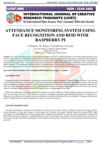
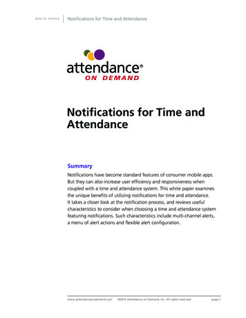
is known as a "sketch".With a few special rules to organize the code, the Arduino IDE basically uses C and C languages. The Arduino IDE comes equipped with a software library, which has manycommonly used I/P and O/P procedures. A typical Arduino C/C program would compriseof two functions that are compiled and linked together forming the program. The sketch is acyclic executive program:setup(): this function runs once at the beginning of a sketch and is used to initialize devices/settings.loop(): a function called repeatedly till the device is in use. This runs until the Arduinoboardis powered off.After the GNU toolchain has been linked and the program complied, the Arduino IDE uses aprogram to convert the executable code or the program into a text file in hexadecimalcoding. Using a loader software provided in the firmware of the board, the programis thenloaded into the Arduino Uno board.2.2 The UNO BoardThe Uno is a MCU board based on the ATmega328P. It has been provided with 14 digitalI/O pins (of these 6 can be employed as PWM O/Ps), 6 analog I/Ps, a USB connection, a 16MegaHz quartz crystal, an ICSP header, a power jack and a reset button. It has everythingrequired to support the microcontroller; we just got to connect it to a computer or any suchprocessing device with the provided USB cable or it can be powered using a 5V- 12V ACto-DC adapter or appropriate battery to begin operation. We can experiment with our Unowithout thinking about doing something wrong, at worst we may damage the MCU. This canPage 11
be easily rectified by replacing the chip cheaply and just as easily starting over again.Figure2. An Arduino Uno with its Different Parts Labeled2.2.3 CommunicationThe Uno contains a number of facilities and methods to communicate with the uppercomputer, other Uno boards, or with other microcontrollers. The ATmega328 providesUART TTL (5V) serial communication, which is available on digital pins 0 (RX) and 1(TX). An ATmega16U2 on the board channelizes this serial communication on the USB andit will appear as a virtual com port to Arduino IDE on the upper computer. No externaldriver is needed as the 16U2 firmware uses the standard USB COM drivers. However, forWindows operating system, a .inf file is needed. The Arduino Software (IDE) also has aserial monitor, which serves as a output, this allows simple textual data to be sent andPage 12
received from the board.Serial communication on any of the Uno's digital pins is made possible using theSoftwareSerial library provided with the Arduino IDE.ATmega328P also supports I2C (TWI) and SPI Communication. To simplify use of the I2Cbus the Arduino Software (IDE) comes with a Wire library for the purpose.2.2.1 MEMORYThe ATmega328 comes with 32 KiloByte (bootloader utilizes 0.5 KB of the flash). It alsocontains 2 KiloByte of Static RAM and also 1 KiloByte of EEPROM (on which read andwrite is performed with the help EEPROM library).2.2.2 PINSArduino Uno has been provided with 14 Digital Pins which can be used as inputs or outputson user discretion. Using the function pinMode(), digitalRead() and digitalWrite() the pinscan be initiated. 5 volts is standard operational voltage for each of the pins. A current of 20mA flows though these pins under the recommended operating. A maximum current value of40mA mustn’t be exceeded on any Input/Output pin to avoid causing irreparable damage tothe microcontroller.Some pins have specific purpose:Serial Pins: 0 (RX) I/P and 1 (TX) O/P. The use of these two pins is to receive (RX) andtransmit (TX) TTL serial data. The RX and TX LEDs blink when data is transmitted onthese pins.PWM: Pin numbers :3, 5, 6, 9, 10, and 11. Using the analogWrite() function these pinsprovide 8-bit PWM O/P.Page 13
LED: 13.The digital pin 13 drives a built in LED. If the pin has HIGH value, the LED glows,when the pin has a LOW value, it's off.Six clearly labeled pins A0 - A5 are the Arduino Uno’s 6 analog input pins, each providing10 bits of resolution (that is 1024 different digital values). By default the upper end of theirrange is 5 volts and the lower end of the range is at volts. This can be altered using theAREF pin and the analogReference() function.There are a few more other pins on the board:Reset: To reset the microcontroller this line is set to LOW by pressing the reset button.2.2.4 The Fail Safe:To protect our computer's internal parts and its USB ports from shorts and overcurrent, theUno contains a resettable polyfuse. It is known that most computers come with their ownsystem of internal protection, the fuse acts as an extra layer of safety. If a current of valuemore than 500 mA is drawn to or from the USB port, the fuse would automatically break thecircuit till the short or overload is rectified.Page 14
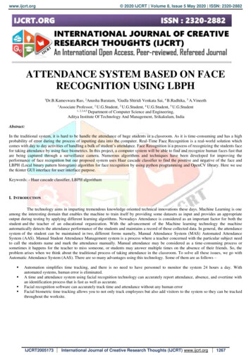
TABLE 1. Specifications of Arduino Uno2.3ATMEGA328P PROCESSORThe ATmega328P is low power Complementary MoS 8bit microcontroller, the architectureof this is based up on the AVR enhancement Reduced instruction set computer architecture.It will execute the instruction in a single clock cycle even the instruction s powerful.Atmega328P can achieves high throughputs approximately 1 MIPS per MHz, so the designerhave the full flexibility to design and optimize between power consumption and processingspeed.Page 15
Figure3. The ATmega328P MicrocontrollerThe high performance microcontrollers integrate 32KiloBytes flash with read while writefeatures, 23 general purpose input output lines, 1024B EPROM, 32 general purposeregisters, 3 pliable timers with comparison modes, external and internal interrupts, a bytedirectional two wire serial interfaces, serial port SPI, a six channel ten bit analog to digitalconverter, the watch dog timer which can be programmable by using internal oscillator, andpower saving modes which are 5 and software selectable . The device operating range isbetween 1.8-5.5 volts.Page 16
CHAPTER 3R-305 FINGERPRINT SCANMODULEPage 17
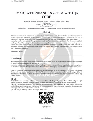
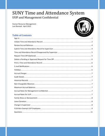
3R-305 FINGERPRINT SCAN MODULE3.1R-305This is a finger print sensor module using a TTL UART interface. The fingerprintinformation saved inside the module can be stored by the user and can be configured in either1:1 or 1: N mode for identifying the person. A 3v3 or 5v Microcontroller can be directlyinterfaced with R-305.When enrolling, user is required to scan finger twice. The system willindependently process the two finger image scans, based on processing results generate atemplate of the finger and then store it. During match routine, user scans the finger tip via theoptical sensor. System generates a template of the fingerprint and compares it with thetemplates stored in the finger library, stored in the flash. For 1:1 matching, system willcompare the live fingerprint with templates stored in the Module; for 1:N matching, thesystem will go through the whole finger library and servers if any to find the matching user.In both circumstances, the matching result, success or failure will be returned by the system.Figure4.A R-305 Fingerprint ModulePage 18
TABLE 2. Specification of R-305 Fingerprint Module3.2 BufferThe module contains an image buffer and two512-byte-character-file buffer within themodule’s RAM space. The buffers can read & written by the user via instructions. Note:Data/ Contents of the mentioned buffers will be lost once the power is off.3.3 Hardware connectionThe MCU of 3.3V of 5V power and the Module may communicate via serial interface: TDconnects with RX (MCU receive pin), RD connects with TX (MCU transfer pin).Page 19
Figure5. Pin Numbering of the two InterfacesTABLE 3. Pins Names and FunctionPin No.NameFunction1.VCCPower input2.GNDSignal ground3.RDData input. TTL logic4.TDData output. TTL logic5.D Data 6.D-Data-7.VCC 5 VDC8.GNDGround3.4 Communication ProtocolWhen communicating, the transfer and receiving of command/data or result is done bywrapping all of them in data package format.Page 20
TABLE 4. Definition of Data PackagePage 21
CHAPTER 4INTERFACING WITH ARDUINO Interfacing LCD Interfacing R-305 Interfacing Command Buttons Page 22
4. INTERFACING4.1 Interfacing LCD with Arduino UnoData pins D4 to D7 are connected to digital pin no. 5, 6 , 7 and 8 of the Arduino.Pin No. 1, 4 (R/W) and pin 16 are grounded.Pin No. 2 and 15 are at 5V.RS (Register select) is connected to pin 3 of Arduino.E (Enable) is connected to pin 4 of Arduino.Figure6. Block Diagram of LCD Pin ConnectionThe LCD pins are connected to the digital and power pins of the Arduino. The LCD libraryavailable in the Arduino IDE is included in the code. Pins 3, 4, 5, 6, 7, 8 are initiated.Page 23
4.2 Interfacing R-305 with Arduino UnoThe module is powered up with 5 V from the Arduino and the GND.RX is connected to Digital pin 10TX is connected to Digital pin 11; serving as input and output respectively.4.3 Interfacing the command buttonsFour buttons are designated for ADD, VERIFY, DELETE and SELECT. They trigger theroutines which carry these functions. The buttons are connected to the pins as:ADD - SW(1) is connected to pin 2DELETE - SW(2) is connected to pin 9VERIFY - SW(1) is connected to pin 12SELECT - SW(4) is connected to pin 134.4 Connection with ArduinoAs described above the connection of various pins are soldered together. A voltage sourceregulator is used to supply 5V supply to the system. This is in case there is no electricity.Further the Arduino Uno and the R-305 module were pasted on the PCB using plasticadhesive. The PCB is inturn stuck to a card board. To improve accessibility the commandbuttons are pasted on a small patch of PCB and stuck further away from the main system.Page 24
Figure7. Block Diagram Showing the Connection of Pins of the SystemPage 25
CHAPTER 5BIOMETRIC SYSTEMSOFTWARE ARCHITECTURE Flowchart Subroutines Routines Page 26
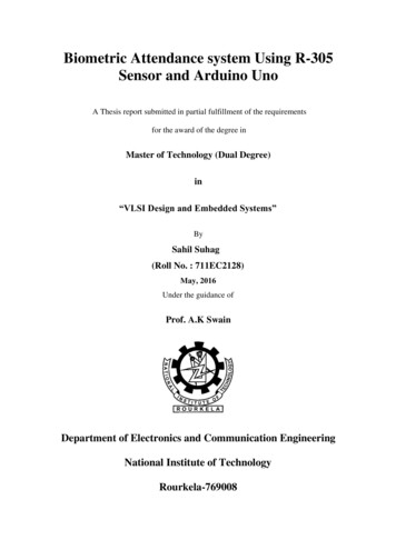
5 BIOMETRIC SYSTEM SOFTWARE ARCHITECTURE5.1 FlowchartFigure8.Flowchart Showing the Execution of the ProgramUpon the execution of this program the various processes will begin functioning. Theseprocesses systematically follow the instructions in the flowchart. Upon powering up thesystem the machine stays in “waiting” mode, this is the idle state in which the machine stayPage 27
until a command is given. On the execution of the command and the routines that follow thesystem again goes into the idle state, until the next command is issued.So upon starting the module the R-305 sensor module and the LCD screen are initiated i.e.they handshake with the Arduino board. If this is successfully achieved the LCD screen lightsup and displays the message “Fingerprint System” followed by the message “FingerprintOK”. The first message is the welcome message and the next message confirms thesuccessful handshake between the fingerprint module and the Arduino Uno. Now the systemstays in idle mode waiting for a command instruction – ADD, DELETE or VERIFY.Upon pressing any of the above three command buttons the corresponding routine isexecuted. The program identifies the key pressed. This initiates the routine to be carried outnext. The system will perform the function of Enroll
1.6 Attendance management system using finger print recognition Maintaining attendance records of students of an institution as large as ours is a tedious task. It takes both time and paper. To change all work regarding attendance to an automated system and on-line, I have built an attendance recording system which can be installed in an