Transcription
Introduction to Fracture MechanicsDavid RoylanceDepartment of Materials Science and EngineeringMassachusetts Institute of TechnologyCambridge, MA 02139June 14, 2001IntroductionIn 1983, the National Bureau of Standards (now the National Institute for Science and Technology) and Battelle Memorial Institute1 estimated the costs for failure due to fracture to be 119 billion per year in 1982 dollars. The dollars are important, but the cost of many failuresin human life and injury is infinitely more so.Failures have occurred for many reasons, including uncertainties in the loading or environment, defects in the materials, inadequacies in design, and deficiencies in construction ormaintenance. Design against fracture has a technology of its own, and this is a very activearea of current research. This module will provide an introduction to an important aspect ofthis field, since without an understanding of fracture the methods in stress analysis discussedpreviously would be of little use. We will focus on fractures due to simple tensile overstress,but the designer is cautioned again about the need to consider absolutely as many factors aspossible that might lead to failure, especially when life is at risk.The Module on the Dislocation Basis of Yield (Module 21) shows how the strength of structural metals – particularly steel – can be increased to very high levels by manipulating themicrostructure so as to inhibit dislocation motion. Unfortunately, this renders the material increasingly brittle, so that cracks can form and propagate catastrophically with very little warning. An unfortunate number of engineering disasters are related directly to this phenomenon,and engineers involved in structural design must be aware of the procedures now available tosafeguard against brittle fracture.The central difficulty in designing against fracture in high-strength materials is that thepresence of cracks can modify the local stresses to such an extent that the elastic stress analysesdone so carefully by the designers are insufficient. When a crack reaches a certain criticallength, it can propagate catastrophically through the structure, even though the gross stress ismuch less than would normally cause yield or failure in a tensile specimen. The term “fracturemechanics” refers to a vital specialization within solid mechanics in which the presence of a crackis assumed, and we wish to find quantitative relations between the crack length, the material’sinherent resistance to crack growth, and the stress at which the crack propagates at high speedto cause structural failure.1R.P. Reed et al., NBS Special Publication 647-1, Washington, 1983.1
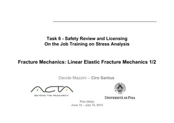
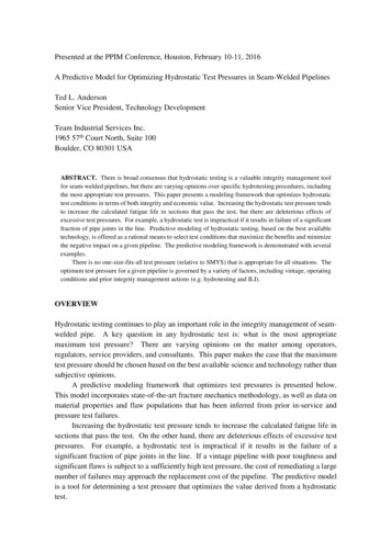
The energy-balance approachWhen A.A. Griffith (1893–1963) began his pioneering studies of fracture in glass in the yearsjust prior to 1920, he was aware of Inglis’ work in calculating the stress concentrations aroundelliptical holes2 , and naturally considered how it might be used in developing a fundamentalapproach to predicting fracture strengths. However, the Inglis solution poses a mathematicaldifficulty: in the limit of a perfectly sharp crack, the stresses approach infinity at the cracktip. This is obviously nonphysical (actually the material generally undergoes some local yieldingto blunt the cracktip), and using such a result would predict that materials would have nearzero strength: even for very small applied loads, the stresses near crack tips would becomeinfinite, and the bonds there would rupture. Rather than focusing on the crack-tip stressesdirectly, Griffith employed an energy-balance approach that has become one of the most famousdevelopments in materials science3 .The strain energy per unit volume of stressed material isU 1V f dx f dx A L σdIf the material is linear (σ E ), then the strain energy per unit volume isσ2E 2 22EWhen a crack has grown into a solid to a depth a, a region of material adjacent to the freesurfaces is unloaded, and its strain energy released. Using the Inglis solution, Griffith was ableto compute just how much energy this is.U Figure 1: Idealization of unloaded region near crack flanks.A simple way of visualizing this energy release, illustrated in Fig. 1, is to regard two triangularregions near the crack flanks, of width a and height βa, as being completely unloaded, while theremaining material continues to feel the full stress σ. The parameter β can be selected so as to2See Module 16.A.A. Griffith, Philosophical Transactions, Series A, Vol. 221, pp. 163–198, 1920. The importance of Griffith’swork in fracture was largely unrecognized until the 1950’s. See J.E. Gordon, The Science of Structures andMaterials, Scientific American Library, 1988, for a personal account of the Griffith story.32
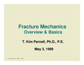
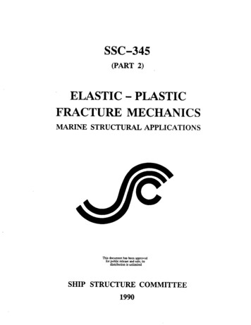
agree with the Inglis solution, and it turns out that for plane stress loading β π. The totalstrain energy U released is then the strain energy per unit volume times the volume in bothtriangular regions:σ2· πa22EHere the dimension normal to the x-y plane is taken to be unity, so U is the strain energyreleased per unit thickness of specimen. This strain energy is liberated by crack growth. But informing the crack, bonds must be broken, and the requisite bond energy is in effect absorbed bythe material. The surface energy S associated with a crack of length a (and unit depth) is:U S 2γawhere γ is the surface energy (e.g., Joules/meter2 ) and the factor 2 is needed since two freesurfaces have been formed. As shown in Fig. 2, the total energy associated with the crack isthen the sum of the (positive) energy absorbed to create the new surfaces, plus the (negative)strain energy liberated by allowing the regions near the crack flanks to become unloaded.Figure 2: The fracture energy balance.As the crack grows longer (a increases), the quadratic dependence of strain energy on aeventually dominates the surface energy, and beyond a critical crack length ac the system canlower its energy by letting the crack grow still longer. Up to the point where a ac , the crackwill grow only if the stress in increased. Beyond that point, crack growth is spontaneous andcatastrophic.The value of the critical crack length can be found by setting the derivative of the totalenergy S U to zero:σf2 (S U ) 2γ πa 0 aESince fast fracture is imminent when this condition is satisfied, we write the stress as σf . Solving, 2Eγπaσf Griffith’s original work dealt with very brittle materials, specifically glass rods. When thematerial exhibits more ductility, consideration of the surface energy alone fails to provide an3
accurate model for fracture. This deficiency was later remedied, at least in part, independentlyby Irwin4 and Orowan5 . They suggested that in a ductile material a good deal – in fact thevast majority – of the released strain energy was absorbed not by creating new surfaces, butby energy dissipation due to plastic flow in the material near the crack tip. They suggestedthat catastrophic fracture occurs when the strain energy is released at a rate sufficient to satisfythe needs of all these energy “sinks,” and denoted this critical strain energy release rate by theparameter Gc ; the Griffith equation can then be rewritten in the form: EGcπaσf (1)This expression describes, in a very succinct way, the interrelation between three importantaspects of the fracture process: the material, as evidenced in the critical strain energy releaserate Gc ; the stress level σf ; and the size, a, of the flaw. In a design situation, one might choose avalue of a based on the smallest crack that could be easily detected. Then for a given materialwith its associated value of Gc , the safe level of stress σf could be determined. The structurewould then be sized so as to keep the working stress comfortably below this critical value.Example 1The story of the DeHavilland Comet aircraft of the early 1950’s, in which at least two aircraftdisintegrated in flight, provides a tragic but fascinating insight into the importance of fracture theory. Itis an eerie story as well, having been all but predicted in a 1948 novel by Nevil Shute named No Highway.The book later became a movie starring James Stewart as a perserverant metallurgist convinced that hiscompany’s new aircraft (the “Reindeer”) was fatally prone to metal fatigue. When just a few years laterthe Comet was determined to have almost exactly this problem, both the book and the movie becamerather famous in the materials engineering community.The postmortem study of the Comet’s problems was one of the most extensive in engineering history6 .It required salvaging almost the entire aircraft from scattered wreckage on the ocean floor and also involvedfull-scale pressurization of an aircraft in a giant water tank. Although valuable lessons were learned, it ishard to overstate the damage done to the DeHavilland Company and to the British aircraft industry ingeneral. It is sometimes argued that the long predominance of the United States in commercial aircraftis due at least in part to the Comet’s misfortune.The Comet aircraft had a fuselage of clad aluminum, with Gc 300 in-psi. The hoop stress due torelative cabin pressurization was 20,000 psi, and at that stress the length of crack that will propagatecatastrophically isa Gc E(300)(11 106 ) 2.62 πσ 2π(20 103 )2A crack would presumably be detected in routine inspection long before it could grow to this length. Butin the case of the Comet, the cracks were propagating from rivet holes near the cabin windows. Whenthe crack reached the window, the size of the window opening was effectively added to the crack length,leading to disaster.Modern aircraft are built with this failure mode in mind, and have “tear strips” that are supposedlyable to stop any rapidly growing crack. But this remedy is not always effective, as was demonstratedin 1988 when a B737 operated by Aloha Airlines had the roof of the first-class cabin tear away. Thataircraft had stress-corrosion damage at a number of rivets in the fuselage lap splices, and this permitted4G.R. Irwin, “Fracture Dynamics,” Fracturing of Metals, American Society for Metals, Cleveland, 1948.E. Orowan, “Fracture and Strength of Solids,” Report of Progress in Physics, Vol. 12, 1949.6T. Bishop, Metal Progress, Vol. 67, pp. 79–85, May 1955.54
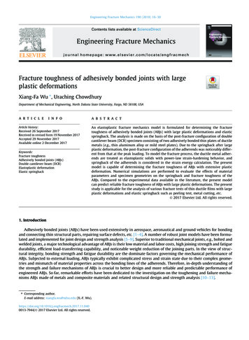
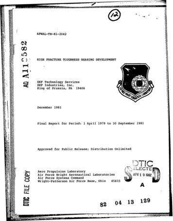
multiple small cracks to link up to form a large crack. A great deal of attention is currently being directedto protection against this sort of “multi-site damage.”It is important to realize that the critical crack length is an absolute number, not dependingon the size of the structure containing it. Each time the crack jumps ahead, say by a smallincrement δa, an additional quantity of strain energy is released from the newly-unloaded material near the crack. Again using our simplistic picture of a triangular-shaped region that is atzero stress while the rest of the structure continues to feel the overall applied stress, it is easyto see in Fig. 3 that much more more energy is released due to the jump at position 2 than atposition 1. This is yet another reason why small things tend to be stronger: they simply aren’tlarge enough to contain a critical-length crack.Figure 3: Energy released during an increment of crack growth, for two different crack lengths.Example 2Gordon7 tells of a ship’s cook who one day noticed a crack in the steel deck of his galley. His superiorsassured him that it was nothing to worry about — the crack was certainly small compared with thevast bulk of the ship — but the cook began painting dates on the floor to mark the new length of thecrack each time a bout of rough weather would cause it to grow longer. With each advance of the crack,additional decking material was unloaded, and the strain energy formerly contained in it released. But asthe amount of energy released grows quadratically with the crack length, eventually enough was availableto keep the crack growing even with no further increase in the gross load. When this happened, the shipbroke into two pieces; this seems amazing but there are a more than a few such occurrences that are verywell documented. As it happened, the part of the ship with the marks showing the crack’s growth wassalvaged, and this has become one of the very best documented examples of slow crack growth followedby final catastrophic fracture.Compliance calibrationA number of means are available by which the material property Gc can be measured. One ofthese is known as compliance calibration, which employs the concept of compliance as a ratio of7J.E. Gordon, Structures, or Why Things Don’t Fall Down, Plenum, New York, 1978.5
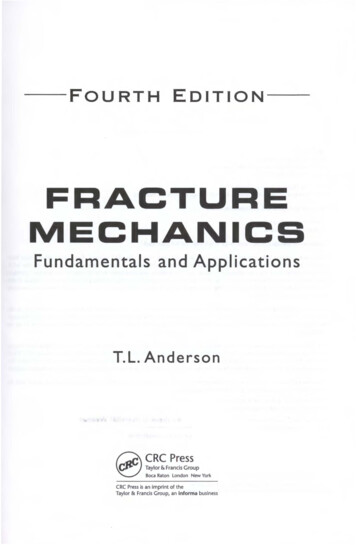
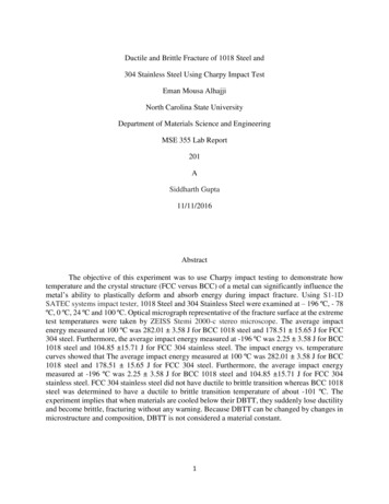
deformation to applied load: C δ/P . The total strain energy U can be written in terms ofthis compliance as:11U P δ CP 222Figure 4: Compliance as a function of crack length.The compliance of a suitable specimen, for instance a cantilevered beam, could be measuredexperimentally as a function of the length a of a crack that is grown into the specimen (seeFig. 4. The strain energy release rate can then be determined by differentiating the curve ofcompliance versus length:1 C U P2(2) a2 aThe critical value of G, Gc , is then found by measuring the critical load Pc needed to fracturea specimen containing a crack of length ac , and using the slope of the compliance curve at thissame value of a:G 1 C Gc Pc22 a a ac(3)Example 3Figure 5: DCB fracture specimen.For a double-cantilever beam (DCB) specimen such as that shown in Fig. 5, beam theory gives thedeflection asP a3δ 23EI6
where I bh3 /12. The elastic compliance is thenδ2a3 P3EIIf the crack is observed to jump forward when P Pc , Eqn. 3 can be used to compute the critical strainenergy release rate asC Gc 1 2 2a212P 2 a2Pc · 2 c32EIb h EThe stress intensity approachFigure 6: Fracture modes.While the energy-balance approach provides a great deal of insight to the fracture process,an alternative method that examines the stress state near the tip of a sharp crack directly hasproven more useful in engineering practice. The literature
Introduction to Fracture Mechanics David Roylance Department of Materials Science and Engineering Massachusetts Institute of Technology Cambridge, MA 02139 June 14, 2001 Introduction ialInstitute1 estimatedthecostsforfailureduetofracturetobe