Transcription
The TransformerThe principle parts of a transformer and their functions are: The core, which makes a path for the magnetic flux. The primary coil, which receives energy from the ac source. The secondary coil, which receives energy from the primary windingand delivers it to the load. The enclosure, which protects the transformer from dirt, moisture, andmechanical damage.1
Transformer Core The composition of a transformer core depends on voltage, current, andfrequency. Commonly used core materials are air, soft iron, and steel. Each ofthese materials is suitable for certain applications. Generally, air-coretransformers are used when the voltage source has a high frequency (above 20kHz). Iron-core transformers are usually used when the source frequency is low(below 20 kHz).A soft-iron-core transformer is very useful where the transformer must bephysically small, yet efficient. The iron-core transformer provides better powertransfer than does the air-core transformer. A transformer whose core isconstructed of laminated sheets of steel dissipates heat readily; thus it providesfor the efficient transfer of power.The majority of transformers contain laminated-steel cores. These steellaminations are insulated with a nonconducting material, such as varnish, andthen formed into a core. It takes about 40 laminations to make a core of 2 cmthick. The purpose of the laminations is to reduce losses which will be discussedlater in this chapter.The most efficient transformer core is one that offers the best path for the mostlines of flux with the least loss in magnetic and electrical energy.2
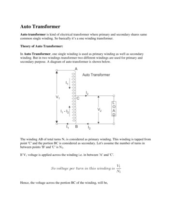
Ideal TransformerCenter-tapped TransformerFigure7.31, 7.323
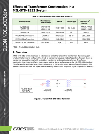
Operation of an Ideal TransformerFigure 7.334
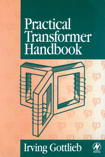
Impedance Reflection Across a TransformerFigure7.345
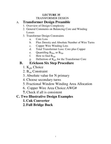
The Maximum Power Transfer Problem in AC CircuitsFigure 7.356
Maximum Power Transfer in an AC Circuit with a TransformerFigure 7.367
Electric Power Transmission: (a) Direct Power Transmission; (b)Power Transmission with TransformersFigure 7.37a,b8
Electric Power Transmission: (c) Equivalent Circuit Seen byGenerator; (d) Equivalent Circuit Seen by Load9Figure 7.37c, d
A Typical Residential Wiring ArrangementFigure7.5210
Structure of an AC Power Distribution NetworkFigure7.5811
Example 1: A transformer reduces voltage from 120 volts in the primaryto 6 volts in the secondary. If the primary winding has 300 turns and thesecondary has 15 turns, find the voltage and turns ratio.12
Example 2: Example 2: An iron core transformer with a primary voltageof 240 volts has 250 turns in the primary and 50 turns in the secondary.Find the secondary voltage.13
Example 3: When operated at 120 V in the primary of an iron coretransformer, the current in the primary is 4 A. Find the current in thesecondary if the voltage is stepped up to 500 V.14
Example 4: A transformer with 480 turns on the primary and 60 turns onthe secondary draws 0.6 amps from a 120 V line. Find Is.15
More About the Transformer!The principle parts of a transformer and their functions are: The core, which makes a path for the magnetic flux. The primary coil, which receives energy from the ac source. The secondary coil, which receives energy from the primary windingand delivers it to the load. The enclosure, which protects the transformer from dirt, moisture, andmechanical damage.16
Applications of Transformers Transformers have many applications in powertransmission and electronics: They may be used to minimise energy losses dueto voltage drop in transmitting electricity overlong distances. They match loads with internal resistance so thatthere is maximum power transfer. They couple signals between electronic stages.17
Transformer Core The composition of a transformer core depends on voltage, current, andfrequency. Commonly used core materials are air, ferrite, soft iron, and steel.Each of these materials is suitable for certain applications. Generally, air-coreand ferrite transformers are used when the source has a high frequency (above20 kHz). Iron-core transformers are usually used when the source frequency islow (below 20 kHz).A soft-iron-core transformer is very useful where the transformer must bephysically small, yet efficient. The iron-core transformer provides better powertransfer than does the air-core transformer. A transformer whose core isconstructed of laminated sheets of steel dissipates heat readily; thus it providesfor the efficient transfer of power.The majority of transformers contain laminated-steel cores. These steellaminations are insulated with a nonconducting material, such as varnish, andthen formed into a core. It takes about 40 laminations to make a core of 2 cmthick. The purpose of the laminations is to reduce losses which will be discussedlater in this chapter.The most efficient transformer core is one that offers the best path for the mostlines of flux with the least loss in magnetic and electrical energy.18
Example 1: A transformer reduces voltage from 120 volts in the primaryto 6 volts in the secondary. If the primary winding has 300 turns and thesecondary has 15 turns, find the voltage and turns ratio.Example 2: Example 2: An iron core transformer with a primaryvoltage of 240 volts has 250 turns in the primary and 50 turns in thesecondary. Find the secondary voltage.Example 3: When operated at 120 V in the primary of an iron coretransformer, the current in the primary is 4 A. Find the current in thesecondary if the voltage is stepped up to 500 V.19
Losses in TransformersAll transformers have copper and core losses, and flux leakage. Copperloss is ohmic power lost in the primary and secondary windings of atransformer due to the ohmic resistance of the windings. Copper loss,in watts, may be found using the following equationCopper Losses Ip Rp Is RsWhere, Ip is the primay current, Is is the secondary current, Rp is theprimary resistance, and Rs is the secondary resistance.Core losses are caused by two factors: hysteresis and eddy currentlosses. Hysteresis loss is that energy lost by reversing the magneticfield in the core as the magnetizing AC rises and falls and reversesdirection. Eddy current loss is a result of induced currents circulatingin the iron core. It can be used by laminations!20
Efficiency of TransformerPower Output 100%Power InputPower OutptEfficiency 100%Power Output Copper Losses Core LossesEfficiency Example 4: A 5:1 step-down transformer has a full-load secondarycurrent of 20 amps. A short circuit test for copper loss at full load givesa wattmeter reading of 100 W. If RP 0.3, find RS and power loss inthe secondary.Ans: RS 0.24; Power Loss in the secondary Is2Rs 96 W.21
Example 2: Example 2: An iron core transformer with a primary voltage of 240 volts has 250 turns in the primary and 50 turns in the secondary. Find the secondary voltage. Example 3: When operated at 120 V in the primary of an iron core transformer, the current in the primary is 4 A. Find the current in the