Transcription
AluventaDesign GuidelineHigh performanceALUMINIUMCONDENSERSDesign guidelinesVersion : 003Date : 01-10-2012 Technology Refrigerant flow Connections Joining Mounting Corrosion Coating Customize design
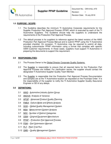
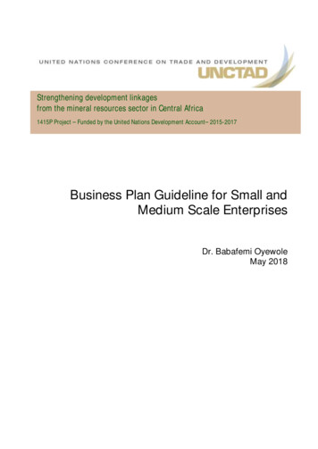
TECHNOLOGYBasic principleIn a single pass condenser the temperatureof the leaving air will be high at the beginningof the condenser where the refrigerant isa superheated gas. Through the middleof the condenser, the temperature of theair will be below condensing temperature,and at the end, where the condensedrefrigerant has become a subcooledliquid, the temperature of the air will below. This means that the temperature ofthe mixed air leaving the condenser willbe approximately 2-5ºK below condensingtemperature.Air flowAir pressure dropDue to the straight through air flow theair pressure drop is low and the lower fanpower results in reduced noise and smalleror less fans.Pa35252001815025mm10018mm50m/s001234MCT designL (m)Due to the minimal height of the microchannel tube the backside turbolence isminimal, leading to reduced noise and lowair pressure drop.Leaving air temperature:2-5K below condensing reAmbient airtemperaturet (ºC)Air2-5 KRefrigerantLeaving airAmbientL (m)0SuperheatCondensingSubcooling5MCT
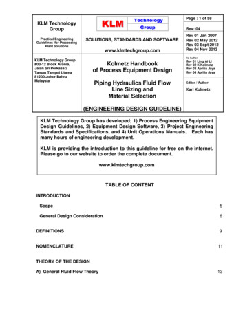
REFRIGERANTFLOWOne pass100% parrallel flowTwo passVertical tubesReduced refrigerant pressure drop.Increased capacity (app. 10%).Only feasible in some applications.
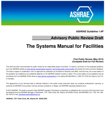
CONNECTIONSSaddleOur dedicated HVAC/R solutions focuson optimal flow and high performance.To improve performance and ensure longlifetime, the connections are normallystrengthened with a flow optimized saddle. Height The saddle is positioned by the followingfactors:Header (left or right side).Height (from bottom of the condenser tothe centerline of the connection).Angle ( /- 0 or 45º).HeightRight headerLeft header 45º 45º0º0ºLeft sideRight side-45º-45ºAir flowTube ards
CONNECTIONSCurrent tube optionsTubeThe tube can be straight or bended (45º or 90º).Direction of the bend: Down, up, forward or backward. 45º18 mm condenser18 mm condenserConnection size (mm)12,716Connection size (mm)Min. distance (mm)158158Min. distance (mm)25 mm condenser18 mm condenser12,716Connection size (mm)3848Min. distance (mm)25 mm condenserConnection size (mm)12,71622Connection size (mm)Min. distance (mm)158158158Min. distance (mm) 45º12,71622Connection size (mm)384842Min. distance (mm)12,716Connection size (mm)Min. distance (mm)107108Min. distance (mm)25 mm condenser12,71622Connection size (mm)Min. distance (mm)107108115Min. distance (mm)2312,7162218232918 mm condenser12,716Connection size (mm)2532Min. distance (mm)25 mm condenserConnection size (mm)18 45º18 mm condenserConnection size (mm)1625 mm condenser 45º18 mm condenser12,712,716182325 mm condenser12,71622Connection size (mm)253242Min. distance (mm)12,71622182329
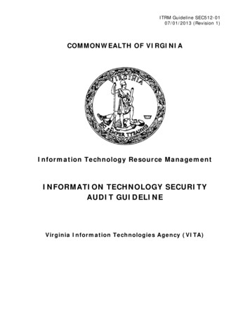
JOININGJoining methodsAluventa recommends brazed joints forjoining connections.Flamebrazed:Al/Cu.For corrosion protection, the flamebrazedjoint must be fitted with a heat shrinkabletube, encapsulating the joint.Joint fitted withheat shrinkable tubeFlamebrazingAluminium - CopperConnection closing methodsThere are several methods for closing connection tubes on our product: Cu-plate with 1/4” Schrader valve. Necessary for coils filled with over 1 bar nitrogenCu-plate. Necessary for coils fill with over 1 bar nitrogenRubber plug. For coils with 1 bar nitrogen or lessPlastic cap. For coils with out pressureCu-plate with1/4” Schrader valve.Cu-plate.Rubber plugPlastic cap.
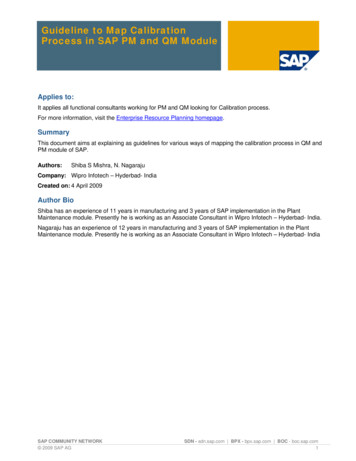
MOUNTINGMounting solutionsC-frameThe C-frame is integrated at the top andbottom of the condenser, and is used formounting the condenser.This can be done by using the groove inthe C-frame. or by inserting screws, rivetsor similar into either side of the C-frame.Connecting two units using the C-frame.Support areaFix areaSupport area
CorrosionCorrosionAny metal exposed to the atmosphere/environment will react with the contents of this environment. These reactions are normallyreferred to as oxidation, corrosion and similar. The extent and nature of the specific reactions that take place depends on the type ofmetal and on the specific contents of the surrounding environment (temperature, humidity, “pollution”, oxygen).Some applications and installation sites can challenge the materials system more than others. Special attention must be paid to thecorrosion severity of the environment at the installation site. An environment in a high corrosion category will have a much higher andnegative impact on the Heat Exchanger than a low corrosion category. Similarly the time of wetness which depends on the operatingpattern and the cleanness of the coil will also have a significant influence on the coils corrosion resistance. The local climate and theimmediate surroundings play a similar role. A nearby industry or local exhausts or emissions can alter an otherwise favorable and cleanenvironment to a corrosive one. Similarly attention must be paid to installations in busses, trucks or trains that passes through manydifferent regions, climates, environments etc.Inappropriate Installation and handling can similarly influence corrosion wear of the heat exchanger. When metals of different typesare in contact, appropriate corrosion protective measures must be taken. When sheet metal or metal piping is being cut or grinded inor near the unit, sprays of metal dust and sparks can reach the Microchannel Heat Exchanger (MCHX) and be the source of a localcorrosion attack. Similarly if for instance rain water can drip onto the Heat Exchanger from bare metal piping or sheet metal etc. Thereare unfortunately many ways in which corrosion attacks can be initiated or stimulated.To identify the possible corrosive initiators and conditions for the heat exchangers the environment is divided in three areas: TheGeneral Environment, the Specific Environment and the Direct Environment. Relevant information on the different environmets and howto evaluate the environments can be found in the Aluventa Selection Guideline.Corrosion ProtectionMaterials system designThe Aluminium alloys used in the Aluventa coils are constantly undergoing evaluation in order for the Aluventa products always to meetthe requirements and obtain the best performance in the field. This is an ongoing activity where Aluventa is working together with leadingAluminium suppliers and international experts and scientists in the task of constant improving the Aluventa materials system.E-coatingOne method of protecting the MCHX against corrosion is coating, some of which have proven reliable in the field over several years.Aluventa is offering an e-coating solution of the Heat Exchanges that will prevent otherwise fast corrosion mechanisms to occur. Due tothe Aluventa coil design and the coating properties this coating has only a very low impact on the coil performance.Aluventa Selection GuidelineAluventa have compiled all our knowhow in the Aluventa Selection Guideline in order guide our customers when selecting a productfor a given operation environment. The Aluventa Selection Guideline gives a relevant information and guidance in how to evaluate aninstallation site and select the right coil for your application.
CoatingElectrofin E-coatingIn order to be able to use the MCHX in aggressive atmospheric conditions the condensers requires a coating. There are severalcorrosion protective coatings available on the marked suitable for HVAC components. Many of which have proven reliable in the fieldover several years. Specifically for the MCHX e-coating is superior to the others.E-coating is a full immersion process where the coil is coated with the aid of electrical power. This guaranties that the complete coilsurface is coated. Also in the center of the fin.E-Coating characteristics are: Proven technology and process.Proven corrosion protection of Aluminium MCHX100% coverage15-30 micron coating layer results in very small performance loss.Aluventa is offering a coating solution via a sub supplier that will prevent eventual fast corrosion mechanisms to occur. Due to theAluventa coil design this coating has only a very low impact on the coil performance. This coating is based on a highly specializedtechnology and only a few companies in the world are able to do this coating and meet the Aluventa specifications.Our coating supplier quarantines the following specifications:Technical performance Dry Film Thickness: 15-30 micron (ASTM D7091-05) Glos -60 : 65-95% (ASTM D523-89) Pencil Hardnes: 2H minimum (ASTM D3363-00) Water Immersion: 1000 hours @ 38 C (ASTM D870-02) Cross Hatch Adhesion: 4B-5B (ASTM D3359-97) Impact Resistance: 160 in./lbs. Direct (ASTM D2794-93) Salt Spray: 6048 hours (ASTM B117-97) Humidity Resistance: 1000 hours minimum (ASTM D2247-99) Durability: Very Flexible, Consistent film Heat transfer reduction: 1% (ARI 410) Bridging: No bridging guaranteed pH Range: 3-12 Temperature limits: -40 – 163 CStandards MIL-C-46168 Chemical agent resistance – DS2, HCl Gas CID-A-A-52474A (GSA) MIL-STD 810F, Method 509.4 (Sand and Dust) MIL-P-53084 (ME)-TACOM Approval MIL-DTL-12468 Decontamination Agent (STB) DPG (Dugway Proving Grounds) Soil & Water Exposure Tests GM9540P-97 Accelerated Corrosion Test (120 cycles) ASTM B117-G85 Modified Salt Spray (Fog) Testing-2000 hours(Tested by ARL for Lockheed Martin)
10CoatingBlygold MicrocoatThe Blygold Microcoat is a polyurethane based UV resistant coating filled with aluminium pigmentation to ensure good heatconductivity. The Microcoat process includes a zirconium based treatment of the heat exchanger for additional protection and adhesionof the top layer. The top layer is applied in a spray process specially developed to penetrate into the center of the Heat exchangerand ensure coverage of the entire surface. The Microcoat is specially adapted to the microchannel technology and is derived fromthe years of experience with corrosion protection of heat exchangers in the field. Our coating supplier guaranties the followingspecifications:Blygold Microcoat characteristics are: Proven technology and process.Proven corrosion protection of Aluminium MCHX100% coverage25 micron coating layer results in very small performance loss.Technical performance of coatingGloss - 60 : 11Pencil Hardness: H (ASTM D3363)Cross Hatch Adhesion: 5B (ASTM D3359-83, ISO2409/3270)Impact Resistance: No visual defects at 5 mm (ISO 1520)Mechanical hardness (Falling sand abrasion): 38.0litresSalt Spray: 4,000 hours (ASTM B117)Acid Salt Spray: 4000 hours (ASTM G85 A1)Coating characteristicsDry Film Thickness: 0,025 mm average.Durability: Very flexible coatingHeat Transfer Reduction: 0,5%Bridging: No Bridging GuaranteedpH Range: 3-11 (long term)Temperature Limits: -30 C to 150 C
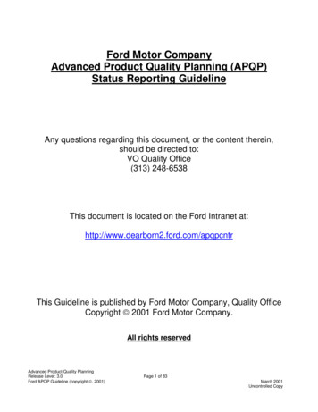
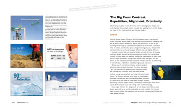
11CustomizeDesignDrawingAll the products are customized so Aluventa will make a specific drawing for each single coil. The drawing will show all details of thecoil including tolerances. This ensures that the customer can use the drawing for design of the application and trust that the coil willfit into the application at the installation.& )UDPH7RS %RWWRP RI FRQGHQVHU FXWV LQ HDFK & IUDPH OO 0HDVXUHV FRQFHUQV WR WKH & SURILOH JHRPHWULDQG JLYH QR LQIRUQDWLRQ UHJDUGLQJ RIIVHW WR WKH KHDGHU'(7 ,/ ' 6& /( LUIDFH [ PP ,QOHW 2XWOHW HDGHU 6(&7,21 6& /( ,5 '(7 ,/ % 6& /( &RUH 6HWXS 3DVV),567 1*/( 352-(.7,21 0HDVXUH DUHD35235,(7 5 1' &21),'(17, / 5(9,6,216 21(5(9 '(6&5,37,21' 7(Condenser / Gas cooler CalculationProgram3UH UHOHDVH Version 12.2 First proposalClient:AluventaProposal No.:Project Name:Project 1Reference:Date:20-08-2012Users Name:Time:10:48:34Refrigerant side'(7 ,/ & 6& /( 33529('NARené MulvadGeometryFin/tube typeHeader DiameterHX height30 [mm]1200 [mm]RefrigerantR410aFace AreaHface2,454 [m ]1180 [mm]Inlet temperatureCondensing temperatureSub cooling80 [ C]50 [ C]Lface2# pipes2,5 [m/s]Face velocityInlet temperature35 [ C]Inlet relative humidityInlet pressure50 [%]22080 [mm]2140 [mm]Core length[ K]Air side# passes% area of total66166 [%]34134 [%]1,013 [Bar]Performance **QT outT inAir82719 [W]35 [ C]Refrigerant82719 [W]80 [ C]P out [ C]47,89 [ C]FlowdP346,7 [ C]49,8922090 [m /h]48,2 [Pa]0,4804 [kg/s]67,08 [kPa] *dP0,9 [ K]2HT area, inside13,25 [m ]HT area, outside81,65 [m ]2* Refrigerant side pressure loss calculated without nozzles and connection pipes** Calculation based on vertical coil arrangement and horizontal airflow. Other arrangements may cause deviations.Proprietary and confidentiality:The information contained in this document is the sole property of basetec product & solutions GmbH. This document may beused only by its recipients for the purpose for which it is provided and only by the recipient, who agrees that it will not, withoutprior written permission of basetec product & solutions GmbH:1) Disclose or use this document or the information in it except as specified above.2) Or make any copies or reproductions in part or in the whole of this document.DERYH XQWLOO LQFO:HOGHG '6 (1 81/(66 27 (5:,6( 63(&,),(' ',0(16,216 5( ,1 PP 1' 5( &&25',1* 72 WROHUDQFH WDEHO*UD\ DQG EURZQ FRORXU FDQ RFFXU RQ RQH VLGHiteration 5 03( WXSHV 72/(5 1&(6 )25 0( 685(0(176 : (5( 127 63(&,),(' 'ZJ QXPEHU OXYHQWD 61RUJHVYHM 6YHQGERUJ& 'ZJ QDPH PP &RQGHQVHU [ PP 7 ( ,1)250 7,21 &217 ,1(' ,1 7 ,6 '5 :,1* ,6 7 ( 62/( 3523(57 2) 5' % 6(7(& SURGXFWV VROXWLRQV *PEK 7 ,6 '5 :,1* 0 %( 86(' 21/ % ,76 5(&,3,(176 &XVWRPHU)25 7 ( 385326( )25 : ,& ,7 ,6 3529,'(' 1' 21/ % 7 ( 5(&,3,(17 : 2 *5((6 7 7 ,7 :,/
Pencil Hardness: H (ASTM D3363) Durability: Very flexible coating Cross Hatch Adhesion: 5B (ASTM D3359-83, ISO2409/3270) Heat Transfer Reduction: 0,5% Impact Resistance: No visual defects at 5 mm (ISO 1520) Bridging: No Bridging Guaranteed Mechanical hardness (Falling sand abrasion): 38.0litres pH Range: 3-11 (long term) Salt Spray: 4,000 hours (ASTM B117) Temperature Limits: -30 C to 150 C .