Transcription
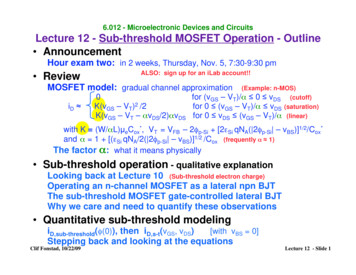
6.012 - Microelectronic Devices and CircuitsLecture 12 - Sub-threshold MOSFET Operation - Outline AnnouncementHour exam two: in 2 weeks, Thursday, Nov. 5, 7:30-9:30 pm ReviewALSO: sign up for an iLab account!!MOSFET model: gradual channel approximationiD (Example: n-MOS)0for (vGS – VT)/α 0 vDS (cutoff)K(vGS – VT)2 /2for 0 (vGS – VT)/α vDS (saturation)K(vGS – VT – αvDS/2)αvDS for 0 vDS (vGS – VT)/α (linear)with K (W/αL)µeCox*, VT VFB – 2φp-Si [2εSi qNA( 2φp-Si – vBS)]1/2/Cox*and α 1 [(εSi qNA/2( 2φp-Si – vBS)]1/2 /Cox (frequently α 1)The factor α: what it means physically Sub-threshold operation - qualitative explanationLooking back at Lecture 10 (Sub-threshold electron charge)Operating an n-channel MOSFET as a lateral npn BJTThe sub-threshold MOSFET gate-controlled lateral BJTWhy we care and need to quantify these observations Quantitative sub-threshold modelingiD,sub-threshold(φ(0)), then iD,s-t(vGS, vDS)[with vBS 0]Stepping back and looking at the equationsClif Fonstad, 10/22/09Lecture 12 - Slide 1
Final comments on αThe Gradual Channel result ignoring α and valid for v BS " 0, and v DS # 0 is:iG (vGS ,v DS ,v BS ) 0, iB (vGS ,v DS ,v BS ) 0, and0iD (vGS ,v DS ,v BS ) K2[vGS " VT (v BS )]2#v &K vGS " VT (v BS ) " DS ' v DS%2 (for!for[vGS " VT (v BS )] 0 v DS0 [vGS " VT (v BS )] v DSfor0 v DS [vGS " VT (v BS )]with K )W**µe Coxand Cox) *ox t oxLWe noted last lecture that these simple expressions without α are easy toremember, and refining them to include α involves easy to remembersubstitutions:v DS " # v DSL "#LK "K #!What we haven't done yet is to look at α itself, and ask what it means.What is it physically?1/xDT(VBS)G!*Cox Si qN A 2 Si 2% p&Si & v BSεox1 SiqN Aεox/tox" # 1 * *Cox 2 2% p&Si & v BSCoxεSiεSi/xDT**"Si x DT"Si t oxCDTCDTB 1 1 1 * *"ox t ox"ox x DTCox CGBClif Fonstad, 10/22/09Lecture 12 - Slide 2[!][]Look back at Lec. 10.
!Foil 7 from Lecture 10MOS Capacitors: the gate charge as vGB is variedqG* [coul/cm2]"22CoxvGB VFB ) (#SiqN A %'("qG 1 1**"'Cox &#SiqN A)"qG" Cox(vGB # VT )InversionLayerCharge qN AP X DTqNAPXDT!DepletionRegionChargeVFB"qG" Cox(vGB # VFB )The charge expressions:", Cox(vGB # VFB )."2. %SiqN A &2CoxvGB # VFB ) )("( 1 qG (vGB ) #1 "(%SiqN A. Cox '*. C " (v # V ) qN X/ ox GBTA DTClif Fonstad, 10/22/09vGB [V]VTAccumulationLayer Charge"Cox#forvGB VFBforVFB vGB VT!VT vGBfor oxt oxLecture 12 - Slide 3
Foil 8 from Lecture 10MOS Capacitors: How good is all this modeling?How can we know?Poisson's Equation in MOSAs we argued when starting, Jh and Je are zero in steadystate so the carrier populations are in equilibrium withthe potential barriers, φ(x), as they are in thermalequilibrium, and we have:n(x) n ie q" (x ) kTandp(x) n ie#q" (x ) kTOnce again this means we can find φ(x), and then n(x) andp(x), by solving Poisson's equation:! d 2" (x)q#q" (x )/ kTq" (x )/ kT #ne#e N d (x) # N a (x)()i2dx [!]This version is only valid, however, when φ(x) -φp.When φ(x) -φp we have accumulation and inversion layers,and we assume them to be infinitely thin sheets of charge,i.e. we model them as delta functions.Clif Fonstad, 10/22/09Lecture 12 - Slide 4
Foil 9 from Lecture 10Poisson's Equation calculation of gate chargeCalculation compared with depletion approximationmodel for tox 3 nm and NA 1018 cm-3:tox,eff 3.2 nmtox,eff 3.3 nmClif Fonstad, 10/22/09We'll look in thisvicinity today.We've ignoredsub-thresholdcharge in ourMOSFET i-vmodelling thusfar.Lecture 12 - Slide 5Plot courtesy of Prof. Antoniadis
Foil 10 from Lecture 10MOS Capacitors: Sub-threshold chargeAssessing how much we are neglectingSheet density of electrons below threshold in weak inversionIn the depletion approximation for the MOS we say that thecharge due to the electrons is negligible before we reachthreshold and the strong inversion layer builds up:*qN (inversion ) (vGB ) "Cox(vGB " VT )But how good an approximation is this? To see, we calculatethe electron charge below threshold (weak inversion):qN (sub"threshold ) (vGB ) " q!0 nex d ( vGB )iq# (x )/ kTdxφ(x) is a non-linear function of x, making the integral difficult," (x) " p !qN A2xx( d)2#Sibut if we use a linear approximation for φ(x) near x 0,where the term in the integral is largest, we can get a verygood approximate analytical expression for the integral.!Clif Fonstad, 10/22/09Lecture 12 - Slide 6
Foil 11 from Lecture 10Sub-threshold electron charge, cont.We begin by saying2qN A [" (0) % " p ]d" (x)" (x) # " (0) ax where %where a dx x 0&SiWith this linear approximation to φ(x) we can do the integraland find!!qN (sub"threshold ) (vGB ) # qkT n(0)kT "qq aq Sin ie q% (0) kT2qN A [% (0) " % p ]To proceed it is easiest to evaluate this expression for variousvalues of φ(0) below threshold (when its value is -φp), and toalso find the corresponding value of vGB, fromvGB " VFB # (0) " # p t ox2 SiqN A [# (0) " # p ] oxThis has been done and is plotted along with the stronginversion layer charge above threshold on the following foil.Clif Fonstad, 10/22/09!Lecture 12 - Slide 7
Foil 12 from Lecture 10Sub-threshold electron charge, cont.6 mVNeglecting this charge in the electrostatics calculation resulted inonly a 6 mV error in our estimate of the threshold voltage value.Today we will look at its impact on the sub-threshold drain current.Clif Fonstad, 10/22/09Lecture 12 - Slide 8
MOSFETs: Conventional strong inversion operation,VGS VTvGS V T GS –n vDS 0 D iDn p-SivBS BHigh concentration ofelectrons in a strong inversionlayer drifting to the drainbecause of field due to v DS .n-type surface channel; drift flux from source to drainIn our gradual channel approximation modeling we have assume ahigh conductivity n-type channel has been induced under the gate.Clif Fonstad, 10/22/09Lecture 12 - Slide 9
MOSFETs: Sub-threshold operation, VGS VTvGS V T GS –n vDS 0 D iDn p-SiA small number of electronssurmount the barrier anddiffuse to drain.vBS BThe electrons diffuse and do not“feel” v DS until they get to theedge of the depletion region.No surface channel; diffusion flux from source to drain when vDS 0For any vGB VFB some electrons in the source can surmount thebarrier and diffuse to the drain. Though always small, this flux canbecome consequential as vGS approaches VT.Clif Fonstad, 10/22/09Lecture 12 - Slide 10
MOSFETs: Sub-threshold operation, VGS VTWhat do we mean by "consequential"?When is this current big enough to matter?There are at least three places where it matters:1. It can limit the gain of a MOSFET linear amplifier.In Lecture 21 we will learn that we achieve maximum gain fromMOSFETs operating in strong inversion when we bias as close tothreshold as possible. This current limits how close we can get.2. It is a major source of power dissipation and heating inmodern VLSI digital ICs.When you have millions of MOSFETs on an IC chip, even a little bitof current through the half that are supposed to be "off" can add upto a lot of power dissipation. We'll see this in Lecture 16.3. It can be used to make very low voltage, ultra-low powerintegrated circuits.In Lecture 25 we'll talk about MIT/TI research on sub-thresholdcircuits with 0.3 V supplies and using µW's of power.Clif Fonstad, 10/22/09Lecture 12 - Slide 11
Sub-threshold Operation of MOSFETs: finding iDBegin by considering the device illustrated below:GS-tox0n n ptn 0xDBLy- Set vGS VFB, and vDS vBS 0.- The potential profile vs. y, φ(y) at any x between 0 and tn is then:-tox0SvGS VFBn GvDS 0Dn pytn xφ(y)φn vBS 0Clif Fonstad, 10/22/090BLy0φpLLecture 12 - Slide 12
Sub-threshold Operation of MOSFETs, cont.- Now consider φ(y) when vGS VFB, vBS 0. and vDS 0:-tox S0vGS VFBGvDS 0Dφ(y)φn vDSn n pvDSφn tn xyvBS 000BLyLφp- So far this is standard MOSFET operating procedure. We couldapply a positive voltage to the gate and when it was larger than VTwe would see the normal drain current that we modeled earlier.Rather than do this, however, consider forward biasing thesubstrate-source diode junction, I.e, vBS 0 Clif Fonstad, 10/22/09Lecture 12 - Slide 13
Sub-threshold Operation of MOSFETs, cont.- Apply vBS 0, keep the same vDS 0, and adjust vGS such thatthe potential at the oxide-Si interface, φ(0,y), equals φp vBS.- Now consider φ(x,y):vGS s.t. φ(0,y) φp vBS-tox0GSElectronInjectionandDiffusionn φ(y)vDS 0φn n ptn xφn vDSD0vBS 00BLyvBSyp',n'- With this biasing the structure isbeing operated as a lateral BJT!The drain/collector current is:DeiD /C " W t n qn i2e qv BS / kT #1N Ap Leff(Clif Fonstad, 10/22/09Lφp vBSφp)n'(0 ) npo(eqvBS/kT-1)0- This is not sub-threshold operation yet.LyLecture 12 - Slide 14
Sub-threshold Operation of MOSFETs, cont.- Now again make vBS 0, but keep the same vDS and vGS so thatthe potential at the oxide-Si interface, φ(0,y), is still φp.- Now φ(x,y) is different for 0 x xD,φ(0,y)and xD x tn :φn vDSvGS s.t. φ(0,y) φpGvDS 0φD-tox S-φp n 0φ(x)xDInjectionn n p0tn xφ(x)-φpyLφpvBS 00BL- Now there is lateral BJT actiononly along the interface.- The drain current that flows inthis case is the sub-thresholddrain current.Clif Fonstad, 10/22/09yφ(y)φn vDSφn 0Lyφp- This is sub-threshold operation!Lecture 12 - Slide 15
Sub-threshold Operation of MOSFETs, cont.- The barrier at the n -p junction is lowered near the oxide-Siinterface for any vGS VFB.- The barrier is lowered by φ(x) - φp for 0 x xD.Plot vs yat fixed x,0 x xD.(This is the effective vBE on the lateral BJT between x and x dx.)-tox SVFB vGS VT G0vDS 0φ(0,y)Dφn vDSInjectionxDn -φpφ(x)n ptn xvBS 00φ(x)BLy- The barrier loweringvGS(effective forward bias)(1) is controlled by vGS,and (2) decreasesquickly with x.vBE,eff(x) [φ(x) φp]Clif Fonstad, 10/22/09φn yφ(x)-φp L0φpPlot vs xat fixed y,0 y L.- φpφ(0)-toxxdxφpInjection occurs over this range.Lecture 12 - Slide 16
Sub-threshold Operation of MOSFETs, cont.- To calculate iD, we first find the current in each dx thick slab:GVFB vGS VTSvDS 0D-tox0xx dxn n pxDvBS 0vDS 0yxn' ( x,0) n i (e q" (x,vGS )/ kT #1) n ie q" (x,vGS )/ kTdiD (x) q DeClif Fonstad, 10/22/09!0Ln' ( x,L) " n ie q# (x,vGD )/ kTn'(x,0) " n'(x,L)WW dx #De q n ie q (x,vGS )/ kT (1" e"qv DS )/ kT ) dxLL!Lecture 12 - Slide 17
Sub-threshold Operation of MOSFETs, cont.- Then we add up all the contributions to get iD:'W 0q" (x,vGS )/ kTiD De & # q n iedx)(1* e*qv DS / kT )L &% x d)(- This is what we called qN(sub-threshold) in Lecture 9 and today on Foil 7.Substituting the expression we found for this (see Foil 7), we have:%WkTiD(sub"threshold ) De 'qL'& q!(#Sin ie q (0,vGS ) kT *(1" e"qv DS / kT )2qN A [ (0,vGS ) " p ]*)- Using the Einstein relation and replacing ni with NAeqφp/kT, we obtain:2#&WkT1*iD(sub"th ) µe Cox% (*L q ' 2Cox2q)Si N Aq {* (0,vGS )"[ "* p ] }e[* (0,vGS ) " * p ]kT(1" e"qv DS / kT- To finish (we are almost done) we need to replace φ(0,vGS) with vGSsince we want the drain current's dependence on the terminal voltage.Clif Fonstad, 10/22/09Lecture 12 - Slide 18)
Sub-threshold Operation of MOSFETs, cont.- The relationship relating φ(0,vGS) and vGS is:vGS VFB1 [" (0) # " p ] * 2 SiqN A [" (0) # " p ]Cox- From this we can relate a change in vGS to a change in φ(0), whichis what we really need. To first order the two are linearly related:!"vGS')dvGS1#" (0) (1 *d (0))* 2Cox 2%SiqN A ), " (0) . n " (0)[ (0) & p ] )"n- In the current equation we have the quantity {φ(0,vGS) - [-φp]}. - φp issimply φ(0,VT), the potential at x 0 when the gate voltage is VT, so{" (0,v!GS) # [#" p ]} {" (0,vGS ) # " (0,VT )} {vGS # VT } n!- Using this and the definition for n, we arrive at:!iD(sub"threshold ) #Clif Fonstad, 10/22/09W*µe CoxL kT ' 2q { vGS "VT } n kTn"1e1" e"qv DS / kT ))(& ) (% q(Lecture 12 - Slide 19
Sub-threshold Operation of MOSFETs, cont.- To fully complete our modeling, we must add two more points:1. The dependences on vBS and vDS:vBS: The threshold voltage depends on vBS. φ(0,VT) does also,i.e. φ(0,VT) - φp-vBS, and so do the junction barriers. Takingthis all into account we find that the only change we need tomake is to acknowledge that n and VT both depend on vBS.vDS: The drain to source voltage introduced a factor (1 - e-qvDS/kT) 1.This is discussed in the handout posted on Stellar.The complete expression for iD is:iD,s"t (vGS ,v DS ,v BS ) #!W*µe CoxL kT ' 2q { vGS "VT (v BS )} n kT1" e"qv DS / kT )(& ) [ n(v BS ) "1] e% q(2. The factor n:The value of n depends on φ(0,vGS). Notice, however, that the subthreshold current is largest as φ(0,vGS) approaches -φp-vBS, so itmakes sense to evaluate it there and take that as its value for allvGS:&* &*(1n " '1 *() 2CoxClif Fonstad, 10/22/092#SiqN A ( (1 - '1 *[ (0) % p ] (, () Cox(#SiqN A 2[%2 p % v BS ] (,** Notice that this is exactly the same expression as that for α!Lecture 12 - Slide 20
Sub-threshold Operation of MOSFETs, cont.- Comparing current levels above and below threshold:The ranges of the two models do not overlap, but is it stillinteresting to compare the largest possible value of the subthreshold drain current model (vGS - VT 0 V),* with the stronginversion model at vGS - VT 0.06 V, 0.1 V, and 0.2 V:iD(sub"threshold )K kT ' 2q v "Vn kT# & ) ( n "1) e { GS T }% q((0.025)2iD(strong inversion )!K"12v V( GS T )2#0.4!0.25(0.06)2(0.1)2(0.2)21vBS 0 1.56 x 10⁻⁴ V2 1.5 x 10⁻³ V2 4 x 10⁻³ V2 1.6 x 10⁻² V2We see that the current in strong inversion drift current quicklybecomes much larger, although only grows quadratically.Clif Fonstad, 10/22/09* This is pushing the model, particularly with regard to thediffusion current model, beyond it's range of strict validity,and is probably somewhat of an over-estimate.Lecture 12 - Slide 21
Sub-threshold Operation of MOSFETs, cont.- Plotting our models for the earlier device: NA 1018 cm-3, tox 3 nm:vBS 0Clif Fonstad, 10/22/09Lecture 12 - Slide 22
Sub-threshold Operation of MOSFETs, cont.- Zooming into a lower current scale: NA 1018 cm-3, tox 3 nm:vBS 0Clif Fonstad, 10/22/09Lecture 12 - Slide 23
Sub-threshold Operation of MOSFETs, cont.- Repeating the plot with a log current scale: NA 1018 cm-3, tox 3 nm:Slope 60 x n mV/decade*Clif Fonstad, 10/22/09* n 1.25 here so 75 mV/decadevBS 0Lecture 12 - Slide 24
Sub-threshold Output Characteristic- We plot a family of iD vs vDS curves with (vGS - VT) as the familyvariable, after first defining the sub-threshold diode saturation2 'current, IS,s-t:WkT*2IS,s"t # µe Cox& ) [ n "1] K o Vt [ n "1]L% q(kTNote : Vt ",qlog iD,s-t!(vGS-VT) -0.12xn Volts10-2 IS,s-t(vGS-VT) -0.18xn Volts10-3 IS,s-t(vGS-VT) -0.24xn VoltsIS,s-tvDSiD,s"t (vGS ,v DS ) # IS,s"t eClif Fonstad, 10/22/09!W*µe CoxL(vGS-VT) -0.06xn Volts10-1 IS,s-t!10-4Ko "q { vGS "VT } n kT"qv DS / kT1"e()Note: The device we modeled had n 1.25, so itfollows a "75 mV rule" [i.e. 60 x n 75].vBS 0Lecture 12 - Slide 25
Sub-threshold Output Characteristic, cont.- To compare this with something we've already seen, consider theBJT and plot a family of iC vs vCE curves with vBE as the familyvariablelog iCvBE 0.66 Volts10 11 αFIESvBE 0.60 Volts10 10 αFIES10 910 8vBE 0.54 VoltsαFIESvBE 0.48 VoltsαFIESvCEiC (v BE ,vCE ) " # F IES e qv BEkT(1 e qvCE / kT)- The two biggest differences are (1) the magnitudes of the IS's,and (2) the factor of "n" in the MOSFET case. The totality of vBEreduces the barrier, whereas only a fraction 1/n of vGS does.!- A third difference is that a BJT has a base current.*Clif Fonstad, 10/22/09Lecture 12 - Slide 26* This is the price paid for having n 1 in a BJT.
Large Signal Model for MOSFET Operating Sub-threshold- The large signal model for a MOSFET operating in the weakinversion or sub-threshold region looks the same model as thatfor a device operating in strong inversion (vGS VT) EXCEPTthere is a different equation relating iD to vGS, vDS, and vBS:We will limit our model tovGS " VT , v DS 3kT /q and v BS 0.D!iDiD (vGS , vDS )GiG ( 0)iG,s"t (vGS ,v DS ,v BS ) 0S,BiD,s"t (vGS ,v DS ,0) # IS,s"t (1" v DS ) e!Clif Fonstad, 10/22/09!Early effectq { vGS "VTo } n kT(1" e"qv DS / kT) 1 for vDS 3 kT/qLecture 12 - Slide 27
6.012 - Microelectronic Devices and CircuitsLecture 12 - Sub-threshold MOSFET Operation - SummarySub-threshold operation - qualitative explanationLook back at Lecture 10(Sub-threshold electron charge)BJT action in depletion/weak inversion layer along oxidethe interfaceMOSFET gate-controlled lateral BJTImportant in/for1. power dissipation in normally-off logic gates2. limiting the gain of strong inversion linear amplifiers3. realizing ultra-low power, very low voltage electronicsQuantitative sub-threshold modelingThis gives us a precise description of the voltage dependenceIt also gives us the information on IS,s-t and n we need fordevice designiD,s"t (vGS ,v DS ,v BS ) # IS,s"t ewith:IS,s"tClif Fonstad, 10/22/09!2 'WkT*# µe Cox& ) [ n "1]L% q(q { vGS "VT (v BS )} n kT&(1and n " '1 *() Cox"qv DS / kT1"e()*(#SiqN A 2[ 2% p v BS ] (,Lecture 12 - Slide 28
MIT OpenCourseWarehttp://ocw.mit.edu6.012 Microelectronic Devices and CircuitsFall 2009For information about citing these materials or our Terms of Use, visit: http://ocw.mit.edu/terms.
(x) is a non-linear function of x, making the integral difficult,! "(x) " p qN A 2# Si x-x d ( ) 2 but if we use a linear approximation for φ (x) near x 0, where the term in the integral is largest, we can get a very good approximate analytical expression for