Transcription
M R P G ag eModels 1000/2000/3000OPERATION MANUAL
MRP Gage Operation ManualModel 1000/2000/3000 2009 Gagemaker LPOMMRP10004-012
MRP Gage Operation ManualModel 1000/2000/3000ContentsIntroductionTechnical SupportProduct Information and Updates44System ComponentsMRP-1000 Component List (Internal and External Setup)MRP-2000 Component List (Internal and External Setup)MRP-3000 Component List (Internal and External Setup)567Setup ProceduresMRP Dimensional Limits ChartSetting Up the MRP Gage for External MeasurementsSetting Up the MRP Gage for Internal MeasurementsZeroing the MRP Gage for External Measurements Using Rod StandardsZeroing the MRP Gage for Internal Measurements Using Rod StandardsZeroing the MRP Gage for External Measurements Using Frame StandardsZeroing the MRP Gage for Internal Measurements Using Frame StandardsZeroing the MRP Gage for External Measurements Using the MIC TRACZeroing the MRP Gage for Internal Measurements Using the MIC TRAC91013172023273138Operating ProceduresInspecting External PartsInspecting Internal PartsDetermining Diameter and Ovality Measurements with the MRP GageMRP Inspection Tolerance Guidelines45474950MRP Accuracy Measurement FactorsThread Shave MeasurementsStandoff vs. Pitch Diameter Change5152Setting Standard CalculationsRod Style Setting Standard DimensionsRod Style Setting Standard Correction FactorsMIC TRAC Setting Standard Dimensions535556MIC TRAC Setting Dimensions for the MRP GageAPI Line Pipe Connections - 1” to 20”API NUE Connections - ¾” to 4½”API EUE Connections - ¾” to 4½”API STC Connections - 4½” to 20”API LTC Connections - 4½” to 20”API Buttress Connections - 4½” to 13⅜”API Buttress Connections – 16” to 20”57575858595959Care and MaintenanceMaintenance TipsWarranty Information60603
MRP Gage Operation ManualModel 1000/2000/3000Congratulations! Your decision to purchase a Gagemaker product above all others on the marketdemonstrates your confidence in our quality and workmanship.To ensure the high performance and operation of our product, we urge you to use the included referencematerials. They contain important information for proper setup and use of the equipment. Also, werecommend that you follow the care and maintenance tips in this manual to keep the equipment workingin top condition.If your questions have not been addressed in our reference materials, contact your localrepresentative or a customer service representative at 713-472-7360.IntroductionThe MRP Gages inspect the pitch diameter and ovality of internal and external tapered threads rangingfrom 1 ½”-20”. The MRP includes three models, which gives the gage its versatility. The different framesizes allow each MRP model to measure a specific range of diameters. The MRP 1000 handlesdiameters from 1 ½” to 4 ½”, the MRP 2000 fits diameters in the 2⅜” to 13⅜” range and the MRP 3000tackles the 8⅝” to 20” diameter range.The tubular rail and block construction allows the MRP gage to set securely on the face of theconnector without any special adjustment. The gage uses two pivoting shoes that rest on the crests ofthe threads during inspection. Any variations in pitch diameter detected during inspection are shown onthe gage’s indicator.Before inspecting parts, the MRP gages must be preset to a nominal predetermined dimension. Fordetermining the gage’s setting dimensions and gauging tolerances, this manual includes tabled settingvalues as well as formulas for calculating setting dimensions. The MRP gages can be preset using Rodor Frame Style setting standards or Gagemaker’s MIC TRAC MIC TRAC measurement center.To inspect parts, the pivot shoes are placed on the crest of the threads of the part and the gage isproperly positioned by sweeping to obtain the largest indicator reading. It is also recommended that thegage be zeroed periodically during use to maintain accurate readings.Technical SupportPhone: 713-472-7360Hours: Monday – Friday 8AM – 5PM (CST)Product Information and UpdatesVisit our web site at: www.gagemaker.com4
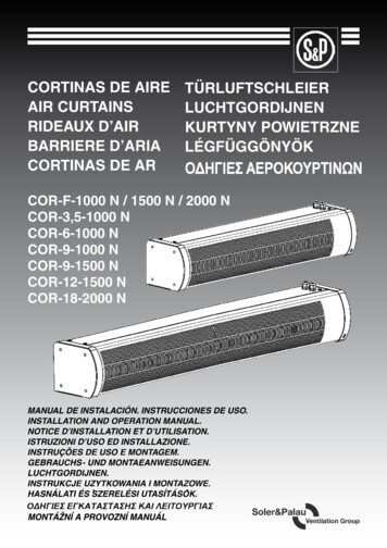
MRP Gage Operation ManualModel 1000/2000/3000System ComponentsTake some time to become familiar with all the parts that make up the three models of the MRPgages by reviewing the labeled diagrams on the following pages. The part names are importantfor understanding the operating instructions.MRP-1000 GageExternal l SetupMRP-1000 Component List (Internal and External nSpring plungerQty12Binder nut/cap screw110Pivot shoe with binder nut23Upper arm assembly111Lower block wear pad14Locking knob412Upper block wear pad15Upper block113Rail26Lower arm1143/32” hex wrench17Lower block1157/64” hex wrench18¼-20 Brass tipped set screw15
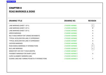
MRP Gage Operation ManualModel 1000/2000/3000MRP-2000 GageInternal Setup139511029817171081316External Setup51615142111361241920Accessories187MRP-2000 Component List (Internal and External Setup)Item1IndicatorDescriptionQty Item1 11Rail (18” set)DescriptionQty22Binder nut/cap screw112Rail (24” set)23Upper arm assembly – MRP-2002113Spring plunger14Upper arm assembly – MRP-2001114Internal pivot shoe with binder nut25Upper block115External pivot shoe with binder nut26Lower arm – MRP-2002116Upper block wear pad17Lower arm – MRP-2001117Lower block wear pad18Lower block118¼-20 Brass tipped set screw49Locking knobs12197/64” hex wrench110Rail (12” set)2201/8” hex wrench16
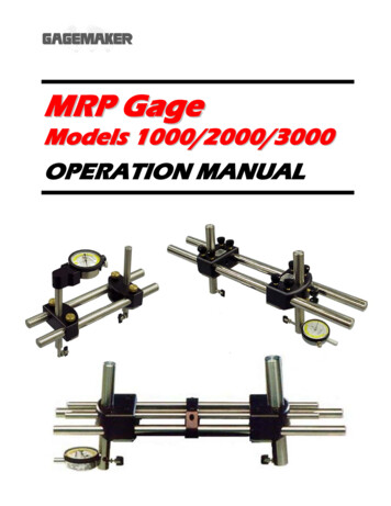
MRP Gage Operation ManualModel 1000/2000/3000MRP-3000 Gage1Internal nal Setup21516MRP-3000 Component List (Internal and External Setup)Item1IndicatorDescriptionQty Item19DescriptionLower rail assemblyQty22Binder nut/cap screw110Pivot shoe with binder nut23Upper arm assembly111Lower block wear pad14Upper block112Upper block15Rail spacer213Upper block wear pad26Upper rail assembly214Locking set screw207Lower arm1157/64” hex wrench18Spring plunger1161/8” hex wrench17
MRP Gage Operation ManualModel 1000/2000/3000MRP Gage SetupB (MIN)A (MIN)A (MAX)B (MIN)A (MIN)B (MAX)A (MAX)C (MAX)B (MAX)C (MIN)C (MAX)C (MIN)MRP 2001 Internal and External Setup – Dimensional LimitsC (MAX)C (MIN)B (MIN)A (MIN)A (MAX)B (MAX)B (MAX)A (MAX)B (MIN)A (MIN)C (MAX)C (MIN)MRP 2002 Internal and External Setup – Dimensional Limits8
MRP Gage Operation ManualModel 1000/2000/3000Setup ProceduresMRP Dimensional Limits ChartThe chart below shows the dimensional limits of each MRP Gage to assist in determining the correctgage model for the application. The MRP can be set up for taking internal and external measurementsas shown in the diagrams on the previous page. All the diagrams are labeled with measurements thatcorrespond to the MRP Dimensional Limits Chart below. Locate the measurement you need on thechart and determine if the MRP gage model falls within the measurement range.ApplicationA MeasurementMIN/MAX Diameter at PivotShoe with Arms RetractedB MeasurementMIN/MAX Diameter at PivotShoe with Arms ExtendedInternal1.50 / 7.6251.375 / 7.375External.875 / 6.252.00 / 7.375Internal6.00 / 23.1256.00 / 22.50External.875 / 20.251.50 / 21.00Internal6.00 / 23.1256.375 / 22.875External.875 / 20.251.875 / 21.375Internal6.50 / 17.1256.50 / 17.125External1.00 / 14.1251.625 / 16.00Internal2.125 / 21.3751.50 / 21.00External3.875 / 22.1254.25 / 22.625Internal2.125 / 21.3751.50 / 20.625External3.875 / 22.1253.875 / 22.25Internal2.125 / 21.3751.50 / 22.25External3.875 / 22.1253.50 / 21.875MRP-3001External6.50 / 20.256.875 / 21.001.00 / 3.375MRP-3002Internal6.50 / 21.3755.75 / 20.6251.00 / 3.375MRP 2002MRP-2002-7MRP-2002-10C MeasurementMIN/MAX Length from WearPad to Center of Pivot Shoe.652 / 3.5.625 / 4.875.625 / 6.875.625 / 9.3751.00/ 3.3751.00/ 5.3751.00/ 8.3759
MRP Gage Operation ManualModel 1000/2000/3000Setting Up the MRP Gage for External MeasurementsMaterials Needed: MRP gagePivot shoes 7/64” hex wrench (supplied with all MRP models)1/8” hex wrench (supplied with MRP-2000/3000 models)Setting up the MRP gage, involves assembling the gage, positioning the upper and lower block correctly,and installing the arms and pivot shoes.Upper Block1. To assemble the gage, slide the rails into theupper and lower blocks, as shown.Lower Block2. Tighten the locking knobs on both the upperand lower blocks to secure them to the rails.Note: For the MRP-3000, use a 1/8” hex wrenchto tighten the four locking set screws onthe upper and lower blocks.3. Insert the arms into the upper and lowerblocks as shown.Note: Be sure that the arms snap intoposition. The arms align with the ballon the inside of each block.10
MRP Gage Operation ManualModel 1000/2000/3000Setting Up the MRP Gage for External Measurements (continued)Upper ArmLower Arm4. Be sure the upper and lower arms arepositioned properly before continuing with thegage setup.5. Insert the indicator into the upper arm.RemoveRemoveContact PointContact PointNote: You’ll need to remove the contact point fromthe indicator stem before inserting theindicator into the arm.6. Using a 7/64” hex wrench, tighten the set screwin the upper arm to secure the indicator.7. Thread one pivot shoe into the indicator stem inthe upper arm.8. Thread the other pivot shoe into the hole in thelower arm.11
MRP Gage Operation ManualModel 1000/2000/3000Setting Up the MRP Gage for External Measurements (continued)9. Align each pivot shoe parallel with the grooveon each arm.10. Gently tighten the binder nut with pliers tosecure. Be careful not to over-tighten thebinder nut, which may cause damage to theindicator.11. Move the pivot shoe back and forth tomake sure it pivots freely.12Groove
MRP Gage Operation ManualModel 1000/2000/3000Setting Up the MRP Gage for Internal MeasurementsMaterials Needed: MRP gagePivot shoes¼-20 brass tipped set screws 3/32” hex wrench (supplied with MRP-1000 model only)7/64” hex wrench (supplied with all MRP models)1/8” hex wrench (supplied with MRP-2000/3000 models)Setting up the MRP gage, involves assembling the gage, positioning the upper and lower block correctly,and installing the arms and pivot shoes.Perform this step for MRP-2000 only.1. Before assembling the gage, remove the twolocking knobs on either end of the upper andlower blocks.Perform this step for MRP-2000 only.2. Insert a ¼-20 brass tipped set screw in eachhole of the upper and lower blocks and tightenusing a 1/8” hex wrench.Insert Set ScrewUpper BlockTighten Set ScrewUpper Block3. To assemble the gage, slide the rails into theupper and lower blocks as shown. Tighten thelocking knobs on both the upper and lowerblocks to secure them to the rails.Note: For the MRP-3000, use a 1/8” hex wrenchto tighten the four locking set screws onthe upper and lower blocks.LowerBlockLowerBlock13
MRP Gage Operation ManualModel 1000/2000/3000Setting Up the MRP Gage for Internal Measurements (continued)4. Insert the arms into the upper and lower blocks,as shown.Note: Be sure that the arms snap intoposition. The arms align with the ball onthe inside of each block.Upper Arm5. Be sure the upper and lower arms arepositioned properly before continuing with thegage setup.Lower ArmInstall ContactPoint6. Install the contact point on the indicator stem.7. Insert the indicator into the upper arm.14
MRP Gage Operation ManualModel 1000/2000/3000Setting Up the MRP Gage for Internal Measurements (continued)8. Using a 7/64” hex wrench, tighten the set screwin the upper arm to secure the indicator.9. Thread each pivot shoe into the upper andlower arms of the MRP.10. Align each pivot shoe parallel with the grooveon each arm.11. Gently tighten the binder nut with pliers tosecure. Be careful not to over-tighten thebinder nut.Groove15
MRP Gage Operation ManualModel 1000/2000/3000Setting Up the MRP Gage for Internal Measurements (continued)12. Move the pivot shoe back and forth tomake sure it pivots freely.16
MRP Gage Operation ManualModel 1000/2000/3000Zeroing the MRP Gage for External Measurements Using Rod StandardsMaterials Needed: MRP gageRod standards 3/32” hex wrench (supplied with MRP-1000 model only)1/8” hex wrench (supplied with MRP-2000/3000 models)To ensure consistent and accurate readings, the MRP gage should be zeroed on a standard onceduring each shift, at a minimum.1. Locate the appropriate MRP rod settingstandard for the desired connector ordimension.Note: MRP rod standards consist of an A rod anda B rod. A is used to set the properdistance between the MRP’s pivot shoes.B is used to set the distance between theMRP’s wear pad and each pivot shoe.2. Loosen the two locking knobs on side of theupper block until the arm slides up and downfreely. Repeat with the lower block.Note: For the MRP-1000, use a 3/32” hexwrench to loosen the set screw on the sideof the upper and lower blocks until thearms slide up and down freely.Note: For the MRP-3000, use a 1/8” hex wrenchto loosen the set screws on the side of theupper and lower blocks until the arms slideup and down freely.3. Place the B standard on the MRP wear padand move the upper arm until the end of thepivot shoe contacts the B standard.17
MRP Gage Operation ManualModel 1000/2000/3000Zeroing the MRP Gage for External Measurements Using Rod Standards (continued)4. Tighten the two locking knobs on the side ofthe upper block to secure the arm. Repeat withthe lower arm.Note: For the MRP-1000, use a 3/32” hex wrenchto tighten the set screw on the side of theupper and lower blocks to secure the arms.Note: For the MRP-3000, use a 1/8” hex wrenchto tighten the set screws on the side of theupper and lower blocks to secure the arms.5. Remove the standard.6. Loosen the locking knobs on the lower block.Note: For the MRP-3000, use a 1/8” hex wrenchto loosen the four locking set screws on thelower block.7. Place the A standard between the pivot shoes.Adjust the lower arm so the pivot shoes contactthe A standard.8. Slide the lower block approximately .050”closer to the upper block to give the MRP gagethe proper preload.9. Tighten the locking knobs on the lower block.Note: For the MRP-3000, use a 1/8” hex wrenchto tighten the four locking set screws on thelower block.18
MRP Gage Operation ManualModel 1000/2000/3000Zeroing the MRP Gage for External Measurements Using Rod Standards (continued)10. Turn the indicator dial on the MRP gage toalign the needle with zero.11. Tighten the indicator clamp.12. Remove the A standard from the MRP gage.Reposition the standard on the gage to verifythe zero setting.Note: Note the position of the small revolutioncounter on the indicator before removingthe gage. Place a piece of masking tape onthe backside of the indicator and record thedial setting of the small revolution counterto eliminate incorrect indicator readings.13. Remove the standard from the gage.14. Set a frequency for verifying the zero setting ofall gages. As a minimum, the MRP gage shouldbe zeroed on a standard once during each shiftto ensure accurate readings.19
MRP Gage Operation ManualModel 1000/2000/3000Zeroing the MRP Gage for Internal Measurements Using Rod StandardsMaterials Needed: MRP gageRod standards 3/32” hex wrench (supplied with MRP-1000 model only)1/8” hex wrench (supplied with MRP-2000/3000 models)To ensure consistent and accurate readings, the MRP gage should be zeroed on a standard onceduring each shift, at a minimum.1. Locate the appropriate MRP rod settingstandard for the desired connector ordimension.Note: MRP rod standards consist of an A rod anda B rod. A is used to set the properdistance between the MRP’s pivot shoes.B is used to set the distance between theMRP’s wear pad and each pivot shoe.2. Using a 1/8” hex wrench, loosen the two setscrews on side of the upper block until thearm slides up and down freely. Repeat withthe lower block.Note: For the MRP-1000, use a 3/32” hexwrench to loosen the set screw on the sideof the upper and lower blocks until thearms slide up and down freely.3. Place the B standard on the MRP wear padand move the upper arm until the end of thepivot shoe contacts the B standard.20
MRP Gage Operation ManualModel 1000/2000/3000Zeroing the MRP Gage for Internal Measurements Using Rod Standards (continued)4. Using the 1/8” hex wrench, tighten the two setscrews on the side of the upper block to securethe arm. Repeat with the lower arm.Note: For the MRP-1000, use a 3/32” hex wrenchto tighten the set screw on the side of theupper and lower blocks to secure the arms.5. Remove the standard.6. Loosen the locking knobs on the lower block.Note: For the MRP-3000, use a 1/8” hex wrenchto loosen the four locking set screws on thelower block.7. Place the A standard on the outside of eachpivot shoe. Adjust the lower arm so the pivotshoes contact the A standard.8. Slide the lower block approximately .050” awayfrom the upper block to give the MRP gage theproper preload.9. Tighten the locking knobs on the lower block.Note: For the MRP-3000, use a 1/8” hex wrenchto tighten the four locking set screws on thelower block.21
MRP Gage Operation ManualModel 1000/2000/3000Zeroing the MRP Gage for Internal Measurements Using Rod Standards (continued)10. Turn the indicator dial on the MRP gage toalign the needle with zero.11. Tighten the indicator clamp.12. Remove the A standard from the MRP gage.Reposition the standard on the gage to verifythe zero setting.Note: Note the position of the small revolutioncounter on the indicator before removingthe gage. Place a piece of masking tape onthe backside of the indicator and record thedial setting of the small revolution counterto eliminate incorrect indicator readings.13. Remove the standard from the gage.14. Set a frequency for verifying the zero setting ofall gages. As a minimum, the MRP gage shouldbe zeroed on a standard once during each shiftto ensure accurate readings.22
MRP Gage Operation ManualModel 1000/2000/3000Zeroing the MRP Gage for External Measurements Using Frame StandardsMaterials Needed: MRP gageFrame standard 3/32” hex wrench (supplied with MRP-1000 model only)1/8” hex wrench (supplied with MRP-2000/3000 models)To ensure consistent and accurate readings, the MRP gage should be zeroed on a standard onceduring each shift, at a minimum.1. Locate the appropriate frame setting standardfor the desired connector or dimension.2. Loosen the locking knobs on the upper block.Note: For the MRP-3000, use a 1/8” hex wrenchto loosen the set screws on the upperblock.3. Place the MRP gage on the frame settingstandard so the pivot shoes are positioned onthe outside of the setting standard.4. Loosen the two locking knobs on the side ofthe upper block until the arm slides up anddown freely. Repeat with the lower block.Note: For the MRP-1000, use a 3/32” hexwrench to loosen the set screw on the sideof the upper and lower blocks until thearms slide up and down freely.Note: For the MRP-3000, use a 1/8” hex wrenchto loosen the set screws on the side of theupper and lower blocks until the arms slideup and down freely.23
MRP Gage Operation ManualModel 1000/2000/3000Zeroing the MRP Gage for External Measurements Using Frame Standards (continued)5. Position both pivot shoes in the center of thesmooth area of the frame setting standard.6. Tighten the two locking knobs on the side ofthe upper block to secure the arm. Repeat withthe lower block.Note: For the MRP-1000, use a 3/32” hex wrenchto tighten the set screw on the side of theupper and lower blocks to secure the arms.Note: For the MRP-3000, use a 1/8” hex wrenchto tighten the set screws on the side of theupper and lower blocks to secure the arms.Slide gagetoward lowerblock7. With the pivot shoe of the upper arm contactingthe standard, slide the entire MRP gage towardthe lower block approximately .050”. Then,slide the lower block until it contacts the framesetting standard, to give the MRP the properpreload.24Slide gage towardlower blockSlide lowerblockforward tocontactstandard
MRP Gage Operation ManualModel 1000/2000/3000Zeroing the MRP Gage for External Measurements Using Frame Standards (continued)8. Once positioned with the proper preload,tighten the locking knobs to secure the upperblock.Note: For the MRP-3000, use a 1/8” hex wrenchto tighten the four locking set screws on theupper block.9. While holding the lower block securely againstthe right side of the standard, sweep the upperblock back and forth to obtain the smallestindicator reading.10. Turn the indicator dial on the MRP gage toalign the needle with zero.25
MRP Gage Operation ManualModel 1000/2000/3000Zeroing the MRP Gage for External Measurements Using Frame Standards (continued)11. Tighten the indicator clamp.Note: Note the position of the small revolutioncounter on the indicator before removingthe gage. Place a piece of masking tape onthe backside of the indicator and record thedial setting of the small revolution counterto eliminate incorrect indicator readings.12. Remove the gage from the frame settingstandard.13. Set a frequency for verifying the zero setting ofall gages. As a minimum, the MRP gage shouldbe zeroed on a standard once during each shiftto ensure accurate readings.26
MRP Gage Operation ManualModel 1000/2000/3000Zeroing the MRP Gage for Internal Measurements Using Frame StandardsMaterials Needed: MRP gageFrame standard 3/32” hex wrench (supplied with MRP-1000 model only)1/8” hex wrench (supplied with MRP-2000/3000 models)To ensure consistent and accurate readings, the MRP gage should be zeroed on a standard onceduring each shift, at a minimum.1. Locate the appropriate frame setting standardfor the desired connector or dimension.2. Loosen the locking knobs on the upper block.Note: For the MRP-3000, use a 1/8” hex wrenchto loosen the set screws on the upperblock.3. Place the MRP gage on the frame settingstandard so the pivot shoes are positioned onthe inside of the setting standard.4. Using a 1/8” hex wrench, loosen the two setscrews, on the side of the lower block, untilthe arm slides up and down freely. Repeatwith the upper block.Note: For the MRP-1000, use a 3/32” hexwrench to loosen the set screw on the sideof the upper and lower blocks until thearms slide up and down freely.27
MRP Gage Operation ManualModel 1000/2000/3000Zeroing the MRP Gage for Internal Measurements Using Frame Standards (continued)5. Position both pivot shoes in the center of thesmooth area of the frame setting standard.6. Using the 1/8” hex wrench, tighten the two setscrews, on the side of the lower block, tosecure the arm. Repeat with the upper block.Note: For the MRP-1000, use a 3/32” hex wrenchto tighten the set screw on the side of theupper and lower blocks to secure the arms.7. With the pivot shoe of the upper arm contactingthe standard, slide the entire MRP gage towardthe upper block approximately .050”. Then,slide the lower block until it contacts the framesetting standard, to give the MRP the properpreload.28Slide gage towardupperblockSlidegage towardupper blockSlide lowerblock backto contactstandard
MRP Gage Operation ManualModel 1000/2000/3000Zeroing the MRP Gage for Internal Measurements Using Frame Standards (continued)8. Once positioned with the proper preload,tighten the locking knobs to secure the upperblock.Note: For the MRP-3000, use a 1/8” hex wrenchto tighten the set screws on the upperblock.9. While holding the lower block securely againstthe left side of the standard, sweep the upperblock back and forth to obtain the smallestindicator reading.10. Turn the indicator dial on the MRP gage toalign the needle with zero.29
MRP Gage Operation ManualModel 1000/2000/3000Zeroing the MRP Gage for Internal Measurements Using Frame Standards (continued)11. Tighten the indicator clamp.Note: Note the position of the small revolutioncounter on the indicator before removingthe gage. Place a piece of masking tape onthe backside of the indicator and record thedial setting of the small revolution counterto eliminate incorrect indicator readings.12. Remove the gage from the frame settingstandard.13. Set a frequency for verifying the zero setting ofall gages. As a minimum, the MRP gage shouldbe zeroed on a standard once during each shiftto ensure accurate readings.30
MRP Gage Operation ManualModel 1000/2000/3000Zeroing the MRP Gage for External Measurements Using the MIC TRACMaterials Needed: MRP gage5/32” hex wrenchCloth MIC TRAC MIC TRAC, CPU, and taper blocks3/32” hex wrench (supplied with MRP-1000 model only)1/8” hex wrench (supplied with MRP-2000/3000 models)To ensure consistent and accurate readings, the MRP gage should be zeroed on the MIC TRAConce during each shift, at a minimum.1. Turn on the MIC TRAC CPU.2. Clean both of the receiver pads and themounting surfaces of the taper blocks using acloth.3. Place the taper block against the receiver padshoulder with the raised side of the blockfacing outward.4. While holding the block against the receiverpad shoulder, insert the two cap screws withwashers into the holes on either side of theblock.5. While applying pressure toward the receiverpad shoulder, use a 5/32" hex wrench totighten the screws.6. Repeat this process with other taper block.31
MRP Gage Operation ManualModel 1000/2000/3000Zeroing the MRP Gage for External Measurements Using the MIC TRAC (continued)7. Turn the coarse adjust knob counterclockwiseto bring the taper blocks together.8. If necessary for documentation purposes,press the PRINT pad on the CPU to recordthe starting location of the blocks.9. Press the EXT pad on the CPU to change toexternal measurement mode.10. Press the ZERO pad on the CPU to zero theMIC TRAC.32
MRP Gage Operation ManualModel 1000/2000/3000Zeroing the MRP Gage for External Measurements Using the MIC TRAC (continued)11. Locate the proper gage setting dimensions onthe MIC TRAC Setting Dimensions for the MRPGage charts in this manual. Locate the chart forthe type of connector being measured. Then,locate the pipe size and use the dimension inthe Pin Dimensions External CPU Readingcolumn.12. Turn the coarse adjust knob on the MIC TRACto display a measurement that is close to thedesired setting dimension.13. Secure the coarse adjust lock.14. Turn the fine adjust knob until the CPU displaysthe exact setting dimension.15. Secure the fine adjust lock.16. If necessary for documentation purposes, pressthe PRINT pad on the CPU to record the actualsetting dimension.17. Loosen the locking knobs on the lower block.Note: For the MRP-3000, use a 1/8” hex wrenchto loosen the set screws on the lower block.33
MRP Gage Operation ManualModel 1000/2000/3000Zeroing the MRP Gage for External Measurements Using the MIC TRAC (continued)18. Loosen the two locking knobs on the side of thelower block until the arm slides up and downfreely. Repeat with the upper block.Note: For the MRP-1000, use a 3/32” hex wrenchto loosen the set screw on the side of theupper and lower blocks until the arms slideup and down freely.Note: For the MRP-3000, use a 1/8” hex wrenchto loosen the set screws on the side of theupper and lower blocks until the arms slideup and down freely.19. Using a scale, adjust both arms to the properMIC TRAC setting dimension (distance fromthe wear pad to the center of the pivot shoe)Refer to the MIC TRAC Setting DimensionsCharts in this manual. Then, tighten the twolocking knobs on the side of the upper andlower blocks, to secure the arm.Note: For the MRP-1000, use a 3/32” hex wrenchto tighten the set screw on the side of theupper and lower blocks to secure the arms.Note: For the MRP-3000, use a 1/8” hex wrenchto tighten the set screws on the side of theupper and lower blocks to secure the arms.During inspection, the pivot shoes shouldrest on full form threads, not black crestedthreads. If necessary, re-adjust the locationof the pivot shoe until the gage measuresonly full form threads.20. Place the MRP gage on the MIC TRAC so thepivot shoes are positioned on the outside of thetaper blocks.34
MRP Gage Operation ManualModel 1000/2000/3000Zeroing the MRP Gage for External Measurements Using the MIC TRAC (continued)21. Position both pivot shoes in the center of thetaper er block22. With the pivot shoe of the upper arm contactingthe taper block, slide the entire MRP gagetoward the lower block approximately .050”.Then, slide the lower block until it contacts theright taper block, to give the MRP the dforwardto tocontacttapercontacttaperblockblock23. Once positioned with the proper preload,tighten the locking knobs to secure the upperblock.Note: For the MRP-3000, use a 1/8” hex wrenchto tighten the set screws on the upperblock.35
MRP Gage Operation ManualModel 1000/2000/3000Zeroing the MRP Gage for External Measurements Using the MIC TRAC (continued)24. While holding the lower block securely againstthe right taper block, sweep the upper blockback and forth to obtain the smallest indicatorreading.25. Turn the indicator dial on the MRP gage toalign the needle with zero.26. Tighten the indicator clamp.Note: Note the position of the small revolutioncounter on the indicator before removingthe gage. Place a piece of masking tape onthe backside of the indicator and record thedial setting of the small revolution counterto eliminate incorrect indicator readings.36
MRP Gage Operation ManualModel 1000/2000/3000Zeroing the MRP Gage for External Measurements Using the MIC TRAC (continued)27. Remove the gage from the taper blocks.28. Set a frequency for verifying the zero setting ofall gages. As a minimum, the MRP gage shouldbe zeroed on a standard once during each shiftto ensure accurate readings.37
MRP Gage Operation ManualModel 1000/2000/3000Zeroing the MRP Gage for Internal Measurements Using the MIC TRACMaterials Needed: MRP gage5/32” hex wrenchCloth MIC TRAC MIC TRAC, CPU, and taper blocks3/32” hex wrench (supplied with MRP-1000 model only)1/8” hex wrench (supplied with MRP-2000/3000 models)To ensure consistent an
sizes allow each MRP model to measure a specific range of diameters. The MRP 1000 handles diameters from 1 ½" to 4 ½", the MRP 2000 fits diameters in the 2⅜" to 13⅜" range and the MRP 3000 tackles the 8⅝" to 20" diameter range. The tubular rail and block construction allows the MRP gage to set securely on the face of the