Transcription
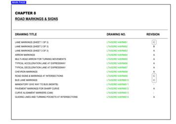
MAIN PAGECHAPTER 8ROAD MARKINGS & SIGNSDRAWING TITLEDRAWING NO.REVISIONLANE MARKINGS (SHEET 1 OF 3)LTA/SDRE14/8/RMS1CLANE MARKINGS (SHEET 2 OF 3)LTA/SDRE14/8/RMS2BLANE MARKINGS (SHEET 3 OF 3)LTA/SDRE14/8/RMS3AARROW MARKINGSLTA/SDRE14/8/RMS4AMULTI-HEAD ARROW FOR TURNING MOVEMENTSLTA/SDRE14/8/RMS5ATYPICAL ACCELERATION LANE AT EXPRESSWAYLTA/SDRE14/8/RMS6ATYPICAL DECELERATION LANE AT EXPRESSWAYLTA/SDRE14/8/RMS7ACHEVRON MARKINGSLTA/SDRE14/8/RMS8AROAD SIGNS & MARKINGS AT INTERSECTIONSLTA/SDRE14/8/RMS9CBUS LANE MARKINGSLTA/SDRE14/8/RMS10CMANDATORY GIVE WAY TO BUS (MGWTB)LTA/SDRE14/8/RMS11-PAVEMENT MARKINGS FOR SHARP CURVELTA/SDRE14/8/RMS12ACURVE ALIGNMENT MARKERS (CAM)LTA/SDRE14/8/RMS13-GUIDING LINES AND TURNING POCKETS AT INTERSECTIONSLTA/SDRE14/8/RMS14A
CHAPTER 8 - MAIN 0001000300100010001000A3These yellow lines are used along normal bus lanes to indicate a breakfor use by other turning vehicles.1.5These white lines are used to indicate the edge of the carriageway adjacent toauxillary lanes eg. exclusive right/left turn lanes at acceleration / deceleration lanesalong expressways. It is also known as speed change lane marking.3.0These broken yellow lines are used to guide drivers emerging from the side road tokeep away from the leftmost traffic lane, which is a normal bus lane. It gives the roadusers advance warning and provides clearer guidance to motorists of normal buslane ahead.1.52002002003.01000A21000These white lines are used to indicate the edge of the carriageway adjacent toauxillary lanes eg. exclusive right / left turn lanes at junctions, lay-by, bus bay,guidling lines etc.1000A11000THERMOPLASTIC PAINT (mm)1000A1000THICKNESS OFDESCRIPTIONThese broken white lines are used to demarcate signalised pedestriancrossing lines.A43001001000300051000A51000100100These broken white lines are used for guiding motorists across junctions.100010001000150A6These yellow and red lines are used along full day bus lane to indicate a breakfor use by other turning vehicles.1.5 (Yellow Line)1.5 (Red Line)These broken yellow and red lines are used to guide drivers emerging from the sideroad, to keep away from the left-most traffic lane, which is a full day bus lane. It givesthe road users advance warning and provides clearer guidance to motorists of full daybus lane ahead.1.5 (Yellow Line)1.5 (Red Line)DIRECTION OF TRAVEL10001003003.0100010001000400150A7DIRECTION OF TRAVEL600600A8These broken white lines are used to demarcate signalised bicycle crossing lines.3.0These white lines are used as lane marking between lanes at other roads & tunnels.3.0These white lines are used as lane marking between lanes on expressway only.3.0These white lines are used as lane markings at light controlled intersection and alongthe approaches at / before the stop line. Generally 7 to 10 markings are 0CNOTES:1. Single / double yellow lines are not required under the following situations:3. The dimensioning lane width shall be taken from the centre of laneSTANDARD DETAILmarkings. See diagram A- flyover and underpass- ramps leasing to flyover and underpasscLLANE WIDTH- slip road (both sides)- edge of traffic island (forming the slip road) at road intersection2. Thermoplastic road marking materials shall comply with SS 589:2013.cLDIAGRAM ACAPR 2019BSEP 2017AOCT 2015REV.DATELANE MARKINGS(SHEET 1 OF 3)DRAWING NO.REV.LTA/SDRE14/8/RMS1DATE OF ISSUE1st APR 2014SCALE1:100CSHEET NO.1 OF 38-1
PREVIOUSCHAPTER 8 - MAIN PAGEMARKINGS150100TYPE10001000150THERMOPLASTIC PAINT (mm)1000D2750THICKNESS OFDESCRIPTION1000NEXTTwo parallel white lines indicate that traffic approaching these lines is to give way to oncoming trafficeither on the left or right.3.0These white lines are used as centre lines on a two-way carriageway.3.0This continuous white line is used as a centre line on a two-way carriageway and also indicatesno parking on both sides.3.0This continuous yellow line by the side of the carriageway indicates no parking from 7.00a.m. to7.00p.m. on that side of the carriageway except sundays and public holidays.(See notes in Dwg No: LTA/SDRE14/8/RMS1)1.5Two parallel continuous white lines are used as centre line on a two-way carriageway orbetween lanes to indicate no crossing of the lines.3.0Two parallel continuous yellow lines by the side of the carriageway indicate no parking atall times on that side of the carriageway. (See notes in Dwg No: LTA/SDRE14/8/RMS1)1.5This continuous white line is used along expressway adjacent to paved shoulder and alsoas stop lines.3.0These zig zag white line are used to indicate approaching zebra crossing. they also indicate nocrossing and no parking at area where these lines are painted.3.0This continuous yellow line is used as normal bus lane 01004000500500K150400015030030012mDIRECTION OF TRAVEL1200L1200 X 200 YELLOW LINE200200NThis continuous white line is used as edgelines painted next to the centre divider kerbs alongdual 3-lane (and above) roads where street lightings are not provided along the centre divider.3.0 (Edgeline)These continuous yellow lines are used for yellow box junction. 200mm for the diagonals and450mm for the sides.3.0450200MSTANDARD DETAILLANE MARKINGS(SHEET 2 OF 3)BSEP 2017AOCT 2015REV.DATEDRAWING NO.REV.LTA/SDRE14/8/RMS2DATE OF ISSUE1st APR 2014SCALE1:100BSHEET NO.2 OF 38-2
PREVIOUSCHAPTER 8 - MAIN PAGE100010001000100010001000500DOUBLE YELLOW LINES100O100010001000THERMOPLASTIC PAINT (mm)Single zig zag yellow line at the edge of a road prohibiting parking at all times.1.5Double zig zag yellow line at the edge of a road prohibiting stopping of vehiclesat all times unless the vehicle is prevented from proceeding due to traffic conditions.1.5500200DOUBLE YELLOW LINES1001000300717P10001001000THICKNESS OFDESCRIPTION100MARKINGS300TYPENEXT1200 x 200 WIDEYELLOW LINE12m9501.5 (Yellow Line)1.5 (Red Line)These continuous yellow & red lines are used as full day bus lane marking.300150Q100DIRECTION OF TRAVEL2Raised profile marking to be provided for the following:- 70300R300300 3008From the start of the shoulder marking at the exit road to 10m behind the gore areaFrom the start of chevron to 10m after the gore areaFrom the start of the deceleration lane along expressway next to paved shoulderContinuously along the expressway shoulder lane next to slow lane300cLcL50 EDGE OF CARRIAGEWAYDROP-INLET CHAMBERDROP-INLET DTHLANEWIDTH400QcL OF YELLOW DTHIcL OF YELLOW P-INLET CHAMBERLANEWIDTHB / B1cLcLLANEWIDTHMLANEWIDTHJ400CENTRE DIVIDER KERBCENTRE DIVIDER KERB400SHOULDERWIDTH400CENTRE DIVIDER KERBEDGE OF CARRIAGEWAYOTHER ROADSSCALE 1:200FULL DAY BUS LANESCALE 1:200NORMAL BUS LANEEXPRESSWAY / TUNNEL LANESCALE 1:200SCALE 1:200STANDARD DETAILLANE MARKINGS(SHEET 3 OF 3)AOCT 2015REV.DATEDRAWING NO.REV.LTA/SDRE14/8/RMS3DATE OF ISSUE1st APR 2014SCALEAS SHOWNASHEET NO.3 OF 38-3
PREVIOUSCHAPTER 8 - MAIN 150050033506301830190518030046055018060 3885455485660R43053045532003200713R990100R 500018018060 60 990180200042522854551250R61022852285152575030 60 305123305305305350 200460TO INDICATE CERTAINTRAFFIC MOVEMENTWITH TIME LIMITNOTES:STANDARD DETAIL1. Thickness of thermoplastic paint is 3mm.DRAWING NO.ARROW MARKINGSAOCT 2015REV.DATEREV.LTA/SDRE14/8/RMS4DATE OF ISSUE1st APR 2014SCALE1:50ASHEET NO.1 OF 18-4
PREVIOUSNEXT200150CHAPTER 8 - MAIN IAN CROSSING LINEKERB LINEOVERALL DIAGRAMWITH JUNCTIONLAYOUTNOT TO SCALENOTES:STANDARD DETAIL1. Thickness of thermoplastic paint is 3mm.MULTI-HEAD ARROWFOR TURNING MOVEMENTSAOCT 2015REV.DATEDRAWING NO.REV.LTA/SDRE14/8/RMS5DATE OF ISSUE1st APR 2014SCALE1:50ASHEET NO.1 OF 18-5
CHAPTER 8 - MAIN PAGERAISEDBEGR KERBTOTAP ADUAERED LLY(5mDLENOGT LFROM EXPRESSWAYTO STARTOFFULLYRAISEDKERB35m2m SHOULDERENTRYRAMPRSTART OFPREVIOUS35mEDGE OF .5m3.5m3.5m3.5m0.9m0.9m0.9mSHOULDERH 3 2 1S3.5m3.5m2.75m2.75m SHOULDERR3.5m3.5m3.5m0.9mRJ12mSTART OFR90mTOTAL LENGTH OF ACCELERATION LANERAISEDKBEERGBTTAP RADUOAERED LLY(5mDLENOWNGTH)RMINIMUMB1PARALLEL LANE (L)35mPHYSICALNOSINGBJA2RTYPICAL ACCELERATION LANE FOR SINGLE LANE ENTRY RAMPSCALE 1:100060m5m40mENDOFRAISEDKERB35mENTRYRAMPEXTEND GUARDRAIL FROM EXPRESSWAYTO START OF FULLY RAISED KERB35m2m SHOULDER35mEDGE OF CARRIAGEWAYR2.75m SHOULDER3.5m2.75m2.75m 5m0.9m0.9m0.9m2.5mH 3 2 1S2.75m3.5m3.5m3.5m0.9mRJRJA2B1RLENGTH OF PARALLEL LANE (L)12mDESIRABLE175mABSOLUTE(SUBJECT TO LTA'S APPROVAL)105m35m90mPARALLEL LANE (L)PHYSICALNOSINGTOTAL LENGTH OF ACCELERATION LANETYPICAL ACCELERATION LANE FOR TWO LANE ENTRY RAMPSCALE 1:1000NOTES:STANDARD DETAIL1. Appropriate width of the slip road shall be provided based on the various radii ofthe slip road, in accordance to Civil Design Criteria.TYPICAL ACCELERATIONLANE AT EXPRESSWAYASEP 2017REV.DATEDRAWING NO.REV.LTA/SDRE14/8/RMS6DATE OF ISSUE1st APR 2014SCALEAS SHOWNASHEET NO.1 of 28-6
NDGUARD(O STARTEXPRESSWAYTSEDKERB)YRAILOFFULmO BE5RBTEDDKE TAPERESIRALLYH)DUA LENGTARG5mN(DOW5m5.m04m04MUMNIm MI02STARTOFSEDKERBRAI2.75m SHOULDERELECTRONIC MESSAGE ADVISORY SIGN (EMAS)TRAFFIC INFORMATION DISPLAY (TID)B1RRJA2DERm 5m3.5m3.5m0.9m0.9m10mOVERHEAD GANTRYRRSHOULDER3.5m0.9m0.9mCRASH CUSHIONPARALLEL LANE (L)75mJEND OF2.75m2 HAPTER 8 - MAIN PAGE75mCURVE ALIGNMENT MARKER (CAM)12mPHYSICALNOSINGTOTAL LENGTH OF DECELERATION LANETYPICAL DECELERATION LANE AT EXIT FOR SINGLE LANE EXIT DREXTENDGUA(O STARTEXPRESSWAYTSEDKERB)YRAILOFFULm04m04MUMNIm MI02m52.75m SHOULDERm02ELECTRONIC MESSAGE ADVISORY SIGN (EMAS)TRAFFIC INFORMATION DISPLAY m10mOVERHEAD GANTRYCRASH CUSHIONPARALLEL LANE (L)75mRR3.5m0.9m0.9mEND OF3.0m2.75m3.5m0.9mm5.3TRAMPEXI2 TARTOFSEDKERBRAIRJBETODERBERED K YTAP )ESRAI UALL ENGTHDL5mGRA N (DOW75m0.9mCURVE ALIGNMENT MARKER (CAM)12mPHYSICALNOSINGTOTAL LENGTH OF DECELERATION LANETYPICAL DECELERATION LANE AT EXIT FOR TWO LANE EXIT RAMPLENGTH OF PARALLEL LANE (L)DESIRABLE150mMINIMUMABSOLUTE(SUBJECT TO LTA'S APPROVAL)80m10mNOTES:STANDARD DETAIL1. Area between the slip road and main road behind the nosing shall be graded levelwith carriageway and shall be free of signs, trees, lamp posts and other hardobjects except split arrows and object marker sign.2. Total length of the deceleration lane can be further reduced to absolute minimumTYPICAL DECELERATIONLANE AT EXPRESSWAYvalue of 160m due to site constraint subject to approval by LTA.DRAWING NO.REV.LTA/SDRE14/8/RMS7A3. Appropriate width of the slip road shall be provided based on the various radiiof slip road, in accordance to Civil Design Criteria.AREV.SEP 2017DATEDATE OF ISSUE1st APR 2014SCALE1:1000SHEET NO.2 of 28-7
CHAPTER 8 - MAIN PAGENEXTPREVIOUS1501501800DIRECTIONOFTRAVEL90 200150AGEWAYNCARRIGNMENTOFMAIIOW HEVRON MARKING WHERE TWO TRAFFIC STREAMS MERGE300START OR END OFDIRECTION OF TRAVEL180010m150WIDE PAVED SHOULDER2m15060009003001503001509002m90 DIRECTIONOFTRAVEL45 CHEVRON MARKING & RAISED PAVEMENT MARKER ON EXPRESSWAY EXITONOFTRAVELRECTIDI150AGEWAYNCARRIGNMENTOFMAIIOW ALLFOL200DIAGONAL MARKING IN ADVANCE OF MEDIAN ISLAND30010m2mDIRECTION OF TRAVEL150MINIMUM LENGTH 50m600090 AGEWAYNCARRIMAIGNMENTOFIOW ALLFOL1800150150300090090R 600ONOFTRAVELRECTIDI90 150DIRECTIONOFTRAVEL200DIRECTIONOFTRAVELCHEVRON MARKING & RAISED PAVEMENT MARKER ON EXPRESSWAY ENTRANCECHEVRON MARKING WHERE A TRAFFIC STREAM DIVIDESLEGEND :RAISED REFLECTIVE PAVEMENT MARKERS (AMBER)CHEVRON MARKING ON OTHER ROADCHEVRON MARKING ON EXPRESSWAYSCALE 1:100SCALE 1:200NOTES:STANDARD DETAIL1. The raised reflective pavement markers shall be complied with the requirementslaid down in BS 8442:2006, BS EN 12899-1:2007, BS EN 1463-1:2009.2. Thickness of thermoplastic paint is 3mm.DRAWING NO.CHEVRON MARKINGSAOCT 2015REV.DATEREV.LTA/SDRE14/8/RMS8DATE OF ISSUE1st APR 2014SCALEAS SHOWNASHEET NO.1 OF 18-8
CHAPTER 8 - MAIN (MINIMUM)1m(MINIMUM)N1.3m (MINIMUM)1.0m3m10mM3m (MINIMUM)CLEGEND7.0mPRIMARY SIGNALSECONDARY SIGNAL(MINIM UM )SEE INSET A3.5m (DESIRABLE)3.3m (ABSOLUTE MINIMUM)ABK5m5.J10m15m15m30mRIGHT TURN ON GREEN ARROW SIGNAL(DIMENSIONING OF ARROWS MARKING)PEDESTRIAN SIGNALDREFER TO LANE MARKINGSRAISED REFLECTIVE PAVEMENT MARKERS (AMBER)3.5m'PEDESTRIAN CROSSING' SIGN ON FLASHING BEACONSEE INSET B'PEDESTRIAN CROSSING PROHIBITION' SIGNTO BE PLACED PERPENDICULAR TOTHE 'ARROW' SIGN3.2m'ARROW' SIGN TO BE PLACED PARALLELTO SIDE OF ROAD3.5m0.6mAMPEDONTO THENEARESTGNSTO BECLLSIALEANDBLAMPPOSTSWHEREVERPOSSING LSTIEXILAYOUT OF INTERSECTIONSUBJECT TO SO'S APPROVALSCALE 1:750NGANCROSSIm FROM PEDESTRI0OCATED5TO BELXY06025002400Y6001m12m(MINIMUM)Y060EDGE OF CARRIAGEWAY / LANE MARKINGGROUNDLEVEL1mVARIABLEX)UM2m IMNIM(ROADLEVEL6001m(MINIMUM)6006002 NOS. OF 'PEDESTRIAN CROSSING'SIGNS MOUNTED BACK TO BACKUSING TRAFFIC SIGN HOLDER TYPE 2ON THE FLASHING BEACON POLETRAFFICLIGHT POLE(1.2m FROM KERB)50mYROAD TYPEEQUALEQUALTYPICAL DETAIL OF PEDESTRIAN CROSSING SIGNSINSET AON FLASHING BEACON POLESCALE 1:1001mARRANGEMENT OF MERGE ARROWS ON ROAD01560m30m)UMM3m NIIM(EXPRESSWAYOTHER ROAD6m (MINIMUM)CLEAR ZONE060060INSET BSCALE 1:500NOTES:1. For pedestrian crossing with green and red man aspect, crossing is to be paintedwhite.2. For pedestrian crossing without green and red man aspect, crossing is to bepainted yellow.3. However, where site condition necessitates it, the stop line can be more than ametre from the mouth of the junction.4. If the width of centre median does not permit the erection of 'Keep Left' sign,spring-loaded delineator post shall be used.5. The zig zag markings must not overlap existing double yellow lines.SCALE 1:2506. The zig zag markings shall be 350mm away from the road kerb.7. The 'Pedestrian Crossing' sign shall face the oncoming traffic and erectSTANDARD DETAILaway from the road kerb.8. The 'Pedestrian Crossing' sign is to be erected on existing lampost / trafficlight pole / any sign pole that is located less than 1m away from theflashing beacon pole.9. There shall be no additional loading on the flashing beacon pole other than'Pedestrian Crossing' signs.10. Thickness of thermoplastic paint for zebra crossing marking is 3mm.11. Appropriate width of the slip road shall be provided based on the variousradii of slip road, in accordance to civil design criteria.CAPR 2019BSEP 2017AOCT 2015REV.DATEROAD SIGNS & MARKINGSAT INTERSECTIONSDRAWING NO.REV.LTA/SDRE14/8/RMS9DATE OF ISSUE1st APR 2014SCALEAS SHOWNCSHEET NO.1 OF 18-9
PREVIOUSCHAPTER 8 - MAIN PAGELEGENDNEXT3mMIN.PRIMARY SIGNAL3mMIN.SECONDARY SIGNALPEDESTRIAN SIGNALFINSET AREFER TO LANE MARKINGSDSEE INSET AL orQA1 orA6IIA1 orA6CA3 orA7L orQL orQBIEND OF BUSLANE MARKINGA1 orA6END OFBUS LANE MARKINGBUSBUSA46m (MINIMUM)(1200 X 200) YELLOW LINE20m (MINIMUM)20m (MINIMUM)TANGENT POINT50m (MINIMUM)12mTANGENT POINTTANGENT POINTJTANGENT POINTF2400BUS LANE AT SIGNALISED JUNCTION150 300 150150375150150525300900END OF BUSLANE MARKINGEND OF BUSLANE MARKINGL orQL orQA1 orA6(1200 X 200)YELLOW LINEBUS2700150150300150A3 orA7A1 orA6BUS900300SCALE 1:50020m (MINIMUM)OF TRAVEL900(1200 X 200)YELLOW LINETANGENT POINT300TANGENT POINTDIRECTION20m (MINIMUM)I750150675150675MARKINGS FOR START OF BUS LANESCALE 1:40BUS LANE AT UNCONTROLLED JUNCTION OR OPENINGSCALE 1:500STANDARD DETAILDRAWING NO.CAPR 2019BSEP 2017AOCT 2015REV.DATEBUS LANE MARKINGSREV.LTA/SDRE14/8/RMS10DATE OF ISSUE1st APR 2014SCALEAS SHOWNCSHEET NO.1 OF 18-10
CHAPTER 8 - MAIN PAGEPREVIOUSNEXTBUS BAY300GIVE WAY LINESB1.2m300A18mDIRECTION OF TRAVEL2m50m (MINIMUM)13m15m-30m150MANDATORY GIVE WAY TO BUSSCALE 1:5009006001000500300050050002500135 X 118INLINE 20mm360012005001502000600GIVE WAY LINESNON-SKID YELLOW COLOUR300DETAILSSCALE 1:250'MANDATORY GIVE WAY TO BUS' SIGNSCALE 1:15NOTES:STANDARD DETAIL1. Colour code for the Bus Zone shall be of "BS 381C 355 LEMON" or equivalentfor the section to be coated with yellow.MANDATORY GIVE WAYTO BUS (MGWTB)DRAWING NO.DATE OF ISSUEREV.DATEREV.LTA/SDRE14/8/RMS111st APR 2014SCALEAS SHOWN-SHEET NO.1 OF 18-11
PREVIOUSCHAPTER 8 - MAIN PAGENEXTLEGENDREFER TO LANE MARKINGS100D150DOUBLE AMBER RAISED REFLECTIVEPAVEMENT ONOFTRAVELm0550mNTITANGENTPOTANGENTPOINTRAISED REFLECTIVE PAVEMENT MARKERS AT SHARP CURVE (AT 6m INTERVAL)SCALE SED REFLECTIVE PAVEMENT MARKERS AT SHARP CURVE (AT 5.5m INTERVAL)SCALE 1:200NOTES:STANDARD DETAIL1. The raised reflective pavement markers shall comply with BS 8442:2006,BS EN 12899-1:2007, BS EN 1463-1:2009.2. Sharp curve refers to radius equal to or less than 200m.PAVEMENT MARKINGSFOR SHARP CURVEAOCT 2015REV.DATEDRAWING NO.REV.LTA/SDRE14/8/RMS12DATE OF ISSUE1st APR 2014SCALEAS SHOWNASHEET NO.1 OF 18-12
PREVIOUSCHAPTER 8 - MAIN PAGENEXTTABLE 1:SIZE OF CURVE ALIGNMENT MARKER (CAM)CLASS OF ROADEXPRESSWAYOTHER ROADSIZE OF CAM750 X 900600 X 750REMARKSHEIGHT CLEARANCE OF THE CURVE ALIGNMENTMARKER SHALL NOT BE MORE THAN 1.2mFROM THE GROUND TO THE BOTTOM OFTHE MARKER.ENDOFCURVETARST URVECFOOXRTFE )RE(2EBLTAIF CURVE ALIGNMENT MARKER MOUNTED ONVIADUCT, HEIGHT CLEARANCE OF THE CURVEALIGNMENT MARKER SHALL BE 1.5m.R(REFER TOTABLE 2)TABLE 2:SPACING OF CURVE ALIGNMENT MARKER (CAM) FOR EXPRESSWAYRADIUS OF CURVE - R(m)ONICTELREDIAVRTOFSPACING OF CURVE ALIGNMENT MARKERS - X(m)45CURVE ALIGNMENT MARKER FOR 27Y(REFER TOTABLE 3)TABLE 3:T VEAR RST CUFONOILCT VERE ADI TRFO270NOILCT VERE ADI TRFO150600 X 750 CURVE ALIGNMENT MARKERSPACING OF CURVE ALIGNMENT MARKER (CAM) FOR OTHER ROAD16101 - 15024 15032ONRECTIDIOFTRAVEL50 - 100Y(REFER TOTABLE 3)ZR TOREFE(E 3)TABL14STARTOFCURVE 50STARTOFCURVESPACING OF CURVE ALIGNMENT MARKERS - Z(m)Z(REFER TOTABLE 3)RADIUS OF CURVE - Y(m)TYPICAL HORIZONTAL CURVE (ONE WAY)TYPICAL HORIZONTAL CURVE (TWO WAY)CURVE ALIGNMENT MARKER FOR OTHER ROADNOTES:1. The first CAM shall be placed at a distance of one spacing after the start of theSTANDARD DETAIL4. Minimum three CAM are to be installed at each approach.curve for all roads.2. Last CAM shall be placed at the end of the curve with intermediate CAM equallyplaced.CURVE ALIGNMENTMARKERS (CAM)3. CAM are mandatory for curves with radius less thana) 95m for roads of posted speed limit of 70km/h.REV.DATEREV.LTA/SDRE14/8/RMS13DATE OF ISSUEb) 60m for roads of posted speed limit of 60km/h.CAM may be installed for larger radius curve at the discretion of the authority.DRAWING NO.1st APR 2014SCALE1:1000-SHEET NO.1 of 18-13
CHAPTER 8 - MAIN PAGEPREVIOUSBCA4A4A5M2m2mBJ2mA2m2m)UMM2m NII(MAJJ2mAC2mIAGUIDING LINES COULD BE APPLIED UNDER THE FOLLOWING SCENARIOS:a) For skewed intersections or intersections with crest where the receivinglanes are not clearly seen by motorists and where it is not feasible torealign the intersections;b) For complex intersections (usually large junctions) where motorists needto make right turn across more than 3 lanes (excluding exclusive rightturn lane).Boundary lines could be applied where there may be possible conflictsbetween two opposite turning traffic.FIGURE 2FIGURE 1GUIDING LINESBOUNDARY LINESSCALE 1:1000SCALE 1:1000BBN2(M mINIMUM)MTURNINGPOCKETCCN300AINSET ACAM600A4CA4300JCINSET ATYPICAL ONE LANE TURNING POCKETTYPICAL TWO LANE TURNING POCKETNOT TO SCALESCALE 1:1000NOTES:1. Use 1m mark by 3m gap (A5) for straight guiding lines and 1m mark by 1m gap (A)for curve guiding lines.SCALE 1:1000STANDARD DETAIL4. Guiding lines shall not be painted over yellow box markings.5. The guiding line shall be provided based on the turning swept pathfor all vehicles.2. Guiding lines shall not recommended to be applied directly next to the pedestriancrossing lines where not possible, pedestrian crossing lines and or stop line mayGUIDING LINES ANDTURNING POCKETSAT INTERSECTIONSneed to be offset (at least one lane width) from guiding line.3. Guiding lines shall not intersect with existing turning pocket and shall not be drawnwithin turning pocket.AOCT 2015REV.DATEDRAWING NO.REV.LTA/SDRE14/8/RMS14DATE OF ISSUE1st APR 2014SCALEAS SHOWNASHEET NO.1 OF 18-14
1000 1000 1000 1000 1000 1000 500. cl cl. drop-inlet chamber kerb scale 1:200. other roads. centre divider kerb scale 1:200. full day bus lane. centre divider kerb