Transcription
Application description 02/2014Configuration Examples forS7-400H with PROFINETSIMATIC S7-400H as of en/66644434
Warranty and liabilityWarranty and liabilityNoteThe Application Examples are not binding and do not claim to be completeregarding the circuits shown, equipping and any eventuality. The ApplicationExamples do not represent customer-specific solutions. They are only intendedto provide support for typical applications. You are responsible for ensuring thatthe described products are used correctly. These application examples do notrelieve you of the responsibility to use safe practices in application, installation,operation and maintenance. When using these Application Examples, yourecognize that we cannot be made liable for any damage/claims beyond theliability clause described. We reserve the right to make changes to theseApplication Examples at any time without prior notice.If there are any deviations between the recommendations provided in theseapplication examples and other Siemens publications – e.g. Catalogs – thecontents of the other documents have priority.We do not accept any liability for the information contained in this document. Siemens AG 2014 All rights reservedAny claims against us – based on whatever legal reason – resulting from the use ofthe examples, information, programs, engineering and performance data etc.,described in this Application Example shall be excluded. Such an exclusion shallnot apply in the case of mandatory liability, e.g. under the German Product LiabilityAct (“Produkthaftungsgesetz”), in case of intent, gross negligence, or injury of life,body or health, guarantee for the quality of a product, fraudulent concealment of adeficiency or breach of a condition which goes to the root of the contract(“wesentliche Vertragspflichten”). The damages for a breach of a substantialcontractual obligation are, however, limited to the foreseeable damage, typical forthe type of contract, except in the event of intent or gross negligence or injury tolife, body or health. The above provisions do not imply a change of the burden ofproof to your detriment.Any form of duplication or distribution of these Application Examples or excerptshereof is prohibited without the expressed consent of Siemens Industry Sector.SecurityinformationSiemens provides products and solutions with industrial security functions thatsupport the secure operation of plants, solutions, machines, equipment and/ornetworks. They are important components in a holistic industrial securityconcept. With this in mind, Siemens’ products and solutions undergo continuousdevelopment. Siemens recommends strongly that you regularly check forproduct updates.For the secure operation of Siemens products and solutions, it is necessary totake suitable preventive action (e.g. cell protection concept) and integrate eachcomponent into a holistic, state-of-the-art industrial security concept. Third-partyproducts that may be in use should also be considered. For more informationabout industrial security, visit http://www.siemens.com/industrialsecurity.To stay informed about product updates as they occur, sign up for a productspecific newsletter. For more information, ration Examples for S7-400HEntry-ID: 66644434, V1.2, 02/20142
Table of contentsTable of contentsWarranty and liability. 21Introduction . 42System and Media Redundancy. 53Functionalities of the H-CPUs as of V6.0 . 74Configuration Examples . 84.14.1.14.1.24.1.34.1.44.1.54.1.6 Siemens AG 2014 All rights .3.34.3.4Communication between H system and field level viaPROFINET . 9Standard configuration “open ring” . 9Star-connected PN devices at the MRP ring. 11Star-connected PN devices at the MRP ring in the ring feed. 14MRP ring for distance bridging and in the subordinate ring . 17Increasing the availability when using an H-CPU as singlecontroller . 20Switched PN devices via a switch integrated in the “open ring”and as single I/O via the same switch in star topology . 21Communication between H-CPU and plant PCs . 24PC connection to an H system via a single ring . 25PC connection to two H systems via a single ring . 26PC connection to one H system via a star point . 27PC connection to two H systems via two star points . 28PC connection to an H system via a double ring . 29Interfaces of the H system between superimposed PCs andsubordinate field levels . 31Star-connected via single ring and switched PN devices in startopology at the MRP ring . 32PC connection to an H system via CP 443-1 and standardconfiguration open ring . 33PC connection to two H systems via CP 443-1 and standardconfiguration “open ring” . 34PC connection via double-line and standard configuration “openring” . 355Further Points to consider . 366Related literature . 377History. 37Configuration Examples for S7-400HEntry-ID: 66644434, V1.2, 02/20143
1 Introduction1IntroductionPurpose of this documentThe topic of “fault tolerance” comprises a number of application options, includingthe field level as well as the connection to the plant PCs.As of V6.0 for the H-CPUs, PROFINET can now also be used as field bus.This opens a number of connection possibilities, varying more or less regardingcomplexity and application case.The document on hand shows a number of such connection options; for the fieldlevel, for the connection of plant PCs to the H-controllers, and for the combinationob both.This gives you an overview of the configurations which can be realized withPROFINET. Additional notes on advantages and selection criteria complete thestatements made in order to support you in planning the application of an H-CPUor an H system.Copyright Siemens AG 2014 All rights reservedPROFIBUS/PROFINETThis document focuses on configurations with PROFINET. All previous statementson configurations with PROFIBUS remain valid independent of PROFINET.PROFIBUS and PROFINET have no mutual impact on each other.Required knowledgeUnderstanding this document requires general SIMATIC knowledge basic knowledge on H systems basic knowledge on the PROFINET communication standardThe terms “system redundancy” and “media redundancy”, frequently used in thisdocument, are explained in the chapters below.Usable H-CPUsAll statements in this document refer to H-CPUs as of version 6.0.Topics not covered by this applicationThe following points are not covered in this document: configuration instruction communication with PROFIBUS communication via radioConfiguration Examples for S7-400HEntry-ID: 66644434, V1.2, 02/20144
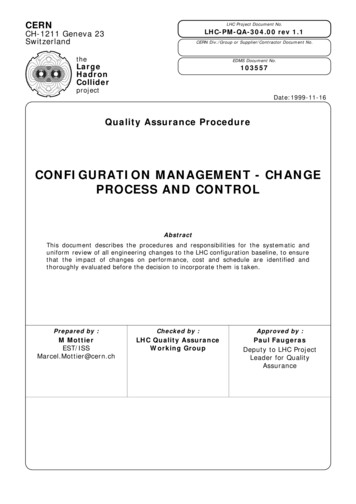
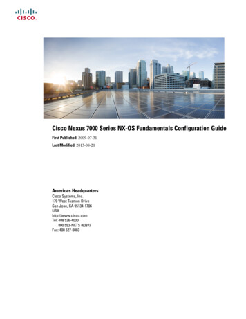
2 System and Media Redundancy2System and Media RedundancyWhat will you learn here?The terms “system redundancy” and “media redundancy” are frequently used inthis document. To also address readers without previous experience in theapplication of H systems or PROFINET, these terms were explained first beforelooking at the individual configuration options in the subsequent chapters.System redundancyRequirement for realizing the system redundancy is the application of an H system.The H system consists of two fault-tolerant controllers (master and reserve CPU). Ifone H-CPU fails, the other automatically takes over.System redundancy is a connection of IO devices via PROFINET(PN devices), for which there is a communication connection between each PNdevice and each of both H-CPUs (see picture below).Copyright Siemens AG 2014 All rights reservedH systemPN devicesThe IO devices need to support the system redundancy; otherwise, they can beoperated in the same network, however only one of both H-CPUs can be assigned(unilateral periphery).The used topology (line, star, ring) plays no role for the system redundancy. Thisdistinguishes the system redundancy from the media redundancy.System redundant periphery is often also referred to as switched I/O. This doesnot refer to the fault tolerance between I/O groups or systems.An example for switched I/O (system-redundant I/O) are PN devices, which supportthe system redundancy and can be assigned to an H system (e.g. ET 200M). Incontrast, the ET 200S, for example, can only be assigned to an H-CPU unilaterally(no H system).Media redundancyMedia redundancy ensures the network availability and contributes to increasingthe plant availability.The ring topology is used here. The media redundancy protocol (MRP) ensuresthat when one transmission path fails, an alternative communication path isavailable.The nodes with PROFINET interface interconnected in the ring use MRP as ofV6.0, if MRP-capable. MRP is part of the PROFINET standardization according toIEC 61158.Configuration Examples for S7-400HEntry-ID: 66644434, V1.2, 02/20145
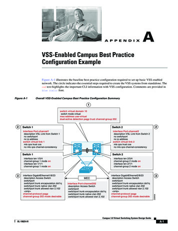
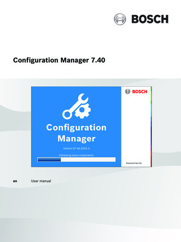
2 System and Media RedundancyFor media redundancy with MRP, one device is the media redundancy manager(MRM), all other devices are redundancy clients. In the picture below, the CPU isthe MRP-Manager.In the case of a failed connection, the MRM selects the alternative communicationpath.CPUCopyright Siemens AG 2014 All rights reservedRingPN devicesContextSystem and media redundancy have no mutual impact on each other.Configuration Examples for S7-400HEntry-ID: 66644434, V1.2, 02/20146
3 Functionalities of the H-CPUs as of V6.03Functionalities of the H-CPUs as of V6.0This chapter gives you supplementary and compact information on updates for theH-CPUs as of V6.0. This information is an extract for a brief overview and does notclaim to be complete.Synchronization module New synchronization modules, however, cables as before (connector of HFSync interfaces is compatible with the previous one) Color coded local and remote coupling at the locking clamp.–black refers to local coupling (6ES7 960–1AA06–0XA0)–blue refers to remote coupling (6ES7 960–1AB06–0XA0) Furthermore, exchange under voltage possible Additional diagnosis of synchronization modules (temperature, aging, )PROFINET interface User data transferCopyright Siemens AG 2014 All rights reserved–In the H system, a maximum of 256 PN devices is supported at bothintegrated PN interfaces. It does not matter whether these can beconfigured unilateral or switched. For an I-Device, only unilateral operation is possible. The H-CPU itself cannot be operated as I-Device. Shared device viewed from the IO controller (only in single operation) Media redundancy (MRP); changeover time approx. 200ms System redundancy Time synchronization–The synchronization occurs via MMS time-of-day messages(Manufacturing Message Specification). The advantage of this method isthe generally higher precision as opposed to the NTP method. Supporting the device exchange without exchangeable medium Not supported:–H-CiR for PROFINET–Web server–CBAThe connection of an external IO controller (CP) is not supported in V6.0 of theH-CPU.Note Various functionalities of the CP 443-1 also exist in the integrated PROFINETinterface (S7 clock time synchronization, H-connections, )Master/reserve changeoverThe master/reserve changeover (MRU) can also be programmed (SFC 90“H-CTRL”).Configuration Examples for S7-400HEntry-ID: 66644434, V1.2, 02/20147
4 Configuration Examples4Configuration ExamplesWhat will you learn here?In this chapter you find configuration options for operating a single H-CPU or an Hsystem in PROFINET networks.For better clarity, the connection with the field level and the connection with theplant PCs are initially displayed separately. Subsequently, possible combinations ofboth connection options are displayed.The chapter on hand is divided into the following sub-chapters: Chap. 4.1: PROFINET communication between H-CPU and field level Chap. 4.2: PROFINET communication between H-CPU and plant PCs Chap. 4.3: combination of field level and plant PCCopyright Siemens AG 2014 All rights reservedThis chapter provides you with an overview on the possible H configurations andwhen to replace the CP 443-1 with the internal PN interface.Configuration Examples for S7-400HEntry-ID: 66644434, V1.2, 02/20148
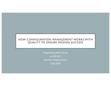
4 Configuration Examples4.1 Communication between H system and field level via PROFINET4.1Communication between H system and field level viaPROFINETIn this chapter, possible configurations between the H system and the field levelare considered and various respective failure scenarios discussed.The pictures of the failure scenarios are marked with a signal light for better clarity.The following convention applies:Availability cannot becompensated4.1.1Availability is mantainedStandard configuration “open ring”DescriptionCopyright Siemens AG 2014 All rights reservedThe picture below shows a system-redundant connection in a so-called open ring.H systemPN devicesFor the open ring, the PN devices are set up as single channel. After the H systemhas gone from single operation to redundant system state, both H-CPUs processthe same program in synchronism. However, process data are only exchangedwith the PN device by one H-CPU.The function of the controller remains at the following faults: failed master CPU, since the reserve CPU automatically takes over. failed I/O station wire breakFor I/O station failure or wire break, the respectively accessible I/O stations arecontrolled by both H-CPUs (advantage over a non-H system).Failure scenariosThe picture below shows a media failure due to wire break as a failure scenarioexample.Configuration Examples for S7-400HEntry-ID: 66644434, V1.2, 02/20149
4 Configuration Examples4.1 Communication between H system and field level via PROFINETMaster CPUReserve CPUPN devicecommunicates withreserve CPUPN device communicateswith master CPUCopyright Siemens AG 2014 All rights reservedTo maintain the functionality by the system redundancy it is unnecessary herewhich of the three connections fails. Both PN devices can exchange process datawith the respective controller process data.Configuration Examples for S7-400HEntry-ID: 66644434, V1.2, 02/201410
4 Configuration Examples4.1 Communication between H system and field level via PROFINET4.1.2Star-connected PN devices at the MRP ringDescriptionThe subsequent picture shows the application of an H system for controlling PNdevices of the field level. The PN devices are connected at the MRP ring in startopologyH systemRing topology:fibre-optics or electricalSCALANCEswitchesCopyright Siemens AG 2014 All rights reservedPN devices(field level)In this configuration, the system as well as the media redundancy can becomeeffective:system redundancy is enabled by using an H system.The system redundancy is supplemented by media redundancy which is achievedby a ring-interconnection of the (external) SCALANCE switches.Combining media and system redundancy can compensate an additional error(failure of an H-CPU) on top of a media failure.System and media redundancy have no mutual impact on each other.All ring nodes must be compatible with the media redundancy protocol (MRP). Thehardware components that can be used as media redundancy manager (MRM) areavailable in the following w/en/23498599Configuration Examples for S7-400HEntry-ID: 66644434, V1.2, 02/201411
4 Configuration Examples4.1 Communication between H system and field level via PROFINETFailure scenario 1: effects of the media redundancyThe following pictures show the path changes through the MRP after a mediafailure.MR ManagerMR ManagerCopyright Siemens AG 2014 All rights reservedConnections where process data is exchangedConnections where no process data is exchangedThe master CPU exchanges process data with the PN devices (left picture).When a connection fails (media failure) within the ring (right picture) the MRmanager ensures an alternative path to continue a guaranteed data exchange withthe PN devices.Failure scenario 2: effects of the system redundancyThe pictures below show the path changes due to a failed master CPU.Connection where process data is exchangedConnections where no process data is exchangedThe process is maintained bumpless by means of the reserve CPU. The mediaredundancy is not required for the failure scenario.Configuration Examples for S7-400HEntry-ID: 66644434, V1.2, 02/201412
4 Configuration Examples4.1 Communication between H system and field level via PROFINETFailure scenario 3: effects of media and system redundancyThe pictures below show the path changes after a failed master CPU and a mediafailure in the (MRP ring).MR ManagerMR ManagerCopyright Siemens AG 2014 All rights reservedConnections where process data is exchangedConnections where no process data is exchangedThe availability remains due to the media and system redundancy. Despite of thefailure of the master CPU and the failure of a ring-connection, the demandedfunctionality is maintained.Configuration Examples for S7-400HEntry-ID: 66644434, V1.2, 02/201413
4 Configuration Examples4.1 Communication between H system and field level via PROFINET4.1.3Star-connected PN devices at the MRP ring in the ring feedDescriptionThe picture below shows the application of an H system for controlling PN devicesof the field level. The PN devices are connected at a MRP ring in star topologyIn contrast to chapter 4.1.2, there is additional periphery here between the H-CPUsand the MRP ring.H systemPN devicesRing topology:fibre optics or electricalAdditional I/OSCALANCEswitchesCopyright Siemens AG 2014 All rights reservedPN devices(field level)SCALANCE switch in the ringEach SCALANCE switch is still located in only one ring (maximum numberpermitted). Apart from the MRP ring, the additionally integrated periphery createsan additional open ring, however, this variant is permitted for a SCALANCE switchto maintain media redundancy. An open ring is not considered a ring here.Open ringMRP ringAll ring nodes must be compatible with the media redundancy protocol (MRP). Thehardware components that can be used as media redundancy manager (MRM) areavailable in the following w/en/23498599Configuration Examples for S7-400HEntry-ID: 66644434, V1.2, 02/201414
4 Configuration Examples4.1 Communication between H system and field level via PROFINETFailure scenario: media failure and/or CPU failureThe picture below shows a failure scenario in which the availability of the system ismaintained even though there are several failures.Copyright Siemens AG 2014 All rights reservedMedia failure and/or CPU failureConnection where process data is exchangedWhen the master CPU and/or the connection from the master CPU fails, the overallsystem can tolerate a further media failure in the MRP ring. It is irrelevant here atwhich point the MPR ring is disconnected.For this scenario, which shows a combination of system and media redundancy, allintact connections for the exchange of process data are not necessary.Generally the following applies: in the system states single operation, link-up orupdate for the S7-400H, the connections between the PN devices in the ring feedand the MRP ring must exist (see next picture). A failure of these connections inthe so-called system states cannot be compensated regarding the overallavailability.Configuration Examples for S7-400HEntry-ID: 66644434, V1.2, 02/201415
4 Configuration Examples4.1 Communication between H system and field level via PROFINETSingle operation, link-up or updateThis connection mustbe availableThese connectionsmust be availableCopyright Siemens AG 2014 All rights reservedConnections where process data is exchangedConnections where no process data is exchangedThe hardware components that can be used as media redundancy manager(MRM) are available in the following w/en/23498599Configuration Examples for S7-400HEntry-ID: 66644434, V1.2, 02/201416
4 Configuration Examples4.1 Communication between H system and field level via PROFINET4.1.4MRP ring for distance bridging and in the subordinate ringDescriptionThe picture below shows the application of an H system for controlling the switchedPN devices within a subordinate MPR ring of the field level.H systemRing version:fibre-optics orelectricalSCALANCEswitchesMRP ringsCopyright Siemens AG 2014 All rights reservedSCALANCEswitchesPN devicesMRP ringI/O within asubordinateMRP ringEach H-CPU is preceded by an MPR ring via the PROFINET interface(two SCALANCE switches per H-CPU). It only serves for bridging the distance tothe sub-ordinate MRP ring.System redundancy is enabled by using an H system. The system redundancy issupplemented by media redundancy which is achieved by a ring-interconnection ofthe (external) SCALANCE switches.The sub-ordinate MRP ring need not necessarily be connected via SCALANCEswitches, but can also be directly connected at the PN devices of the subordinateMRP rings; however, a prerequisite here is the compatibility of the ring nodes withthe media redundancy protocol (MRP). A node is used here as media redundancymanager (MRM).The hardware components that can be used as media redundancy manager(MRM) are available in the following w/en/23498599Configuration Examples for S7-400HEntry-ID: 66644434, V1.2, 02/201417
4 Configuration Examples4.1 Communication between H system and field level via PROFINETFailure scenario 1: media failure in the upper and lower MRP ringThe picture below shows which further failures can still be compensated by theoverall system after a CPU failure.Copyright Siemens AG 2014 All rights reservedMRP ringsMRP ringConnections where process data is exchangedConnection where no process data is exchangedIn addition to the failure of the master CPU, the following can fail in the line inwhich process data is exchanged: any connection in the upper MRP ring and any connection in the lower MRP ring.The overall availability of the system still remains.Configuration Examples for S7-400HEntry-ID: 66644434, V1.2, 02/201418
4 Configuration Examples4.1 Communication between H system and field level via PROFINETFailure scenario 2: failure of a SCALANCE switch in the upper MRP ringA failure of a SCALANCE switch in any of both upper MRP rings cannot becompensated regarding the overall availability.MRP ringsCopyright Siemens AG 2014 All rights reservedMRP ringFailure scenario 3: failure of a SCALANCE switch in the upper and subordinate MRP ringWhen a SCALANCE switch fails in the upper and in the subordinate MRP ring, it isimportant regarding the overall availability which SCALANCE switches fail.MRP ringsMRP ringsMRP ringsMRP ringsConnections where process data is exchangedConnections where no process data is exchangedConfiguration Examples for S7-400HEntry-ID: 66644434, V1.2, 02/201419
4 Configuration Examples4.1 Communication between H system and field level via PROFINET4.1.5Increasing the availability when using an H-CPU as single controllerThe picture below shows an H-CPU as single controller. Redundant PN devicesare connected via the internal PN interface.H-CPUSingle controllerPN devicesRedundant I/OCopyright Siemens AG 2014 All rights reservedWhen an H-CPU (IO controller) fails, the entire process periphery is no longeravailable due to missing system redundancy.When a PN device fails, the functionality of the redundant PN device can only bemaintained if the subordinate of both PN devices in the line fails. If the upper PNdevice fails, the lower can no longer be accessed.Increasing the availabilityThe availability of the PN devices can be increased in a simple way: An MPR ringcan be established by an additional connection. A prerequisite is the MPRcapability of the nodes, where a node performs the function of the mediaredundancy master (MRM).H-CPUSingle controllerPN devicesConfiguration Examples for S7-400HEntry-ID: 66644434, V1.2, 02/201420
4 Configuration Examples4.1 Communication between H system and field level via PROFINET4.1.6Switched PN devices via a switch integrated in the “open ring” and assingle I/O via the same switch in star topologyDescriptionThe picture below shows a PN IO configuration for which the periphery isconnected to an H system via open ring and SCALANCE switch. Additionally,individual PN devices are connected via a star configuration.Both H-CPUs (IO controller) each communicate via the internal PROFINETinterface with the respective redundant assigned PN devices.H systemPN devices via SCALANCE switchintegrated at the H systemin “open ring“Copyright Siemens AG 2014 All rights reservedSCALANCEswitchPN devicesPN devices in star topology viaintegrated SCALANCE switch atthe H systemConfiguration Examples for S7-400HEntry-ID: 66644434, V1.2, 02/201421
4 Configuration Examples4.1 Communication between H system and field level via PROFINETFailure scenario 1: failure of the SCALANCE switchThe pictures below show the effects during a failed SCALANCE switch.Copyright Siemens AG 2014 All rights reservedPN devices via SCALANCE switchintegrated at the H systemin “open ring”PN devices in star topology viaintegrated SCALANCE switch atthe H systemConnections where process data is exchangedConnections where no process data is exchangedA failure of a SCALANCE switch causes the PN devices connected in star topologyto fail. The PN devices in the open ring remain available.Configuration Examples for S7-400HEntry-ID: 66644434, V1.2, 02/201422
4 Configuration Examples4.1 Communication between H system and field level via PROFINETFailure scenario 2: media failure for PN device connected in star topologyThe picture below shows the effects of a failed connection between SCALANCEswitch and the PN devices connected in star topology.Copyright Siemens AG 2014 All rights reservedPN devices via SCALANCE switchintegrated at the H systemin “open ring”PN devices in star topology viaintegrated SCALANCE switch atthe H systemConnections where process data is exchangedConnections where no process data is exchangedIn this example, the central PN switch connected in star topology fails. Theavailability of the lower PN switch could be increased by connecting it directly tothe SCALANCE switch instead of the central PN device.Otherwise, the following applies: for a connection failure of the PN devicesconnected in star topology, the PN device connected at the failed connection fails.The PN devices of the open ring remain unaffected and are still available.Configuration Examples for S7-400HEntry-ID: 66644434, V1.2, 02/201423
4 Configuration Examples4.2 Communication between H-CPU and plant PCs4.2Communication between H-CPU and plant PCsGeneralDue to their hardware and software properties, PCs are not fault-tolerant. However,they can be aligned redundant in a plant. The availability of such a PC system andits data management is ensured by a suitable software such as WinCCRedundancy.Communication takes place via fault-tolerant S7 connections. Connecting to PCstations via fault-tolerant S7 connections only supports Industrial Ethernet.Using fault-tolerant S7 connections between a fault-tolerant system and a PCrequires the "S7-REDCONNECT" software package on the PC. It permitsconnecting a PC to a network with a CP or at a redundant bus system with 2 CPs.Please use the latest version of this software. This software is part of the SIMATICNET CD.Copyright Siemens AG 2014 All rights reservedAs of version 8.1.2, the communication via ISO-on-TCP is supported. The productinformation on the SIMATIC NET PC software informs you of the CPs you can useon the PC side.Configuration Examples for S7-400HEntry-ID: 66644434, V1.2, 02/201424
4 Configuration Examples4.2 Communication between H-CPU and plant PCs4.2.1PC connection to an H system via a single ringDescriptionThe picture below shows the application of an H system for communication with theplant PCs. Communication with an H system is performed via a single ring.Plant PCsSCALANCEswitchesRing version:fibre-optics orelectricalCopyright Siemens AG 2014 All rights reservedH systemThe application of two SCALANCE switches enables achieving media redundancyover larger distances (e.g. up to 26 km with SCALANCE X-200).PC interfaceAs CP for the plant PC, the CP 1613, CP 1613 A2, CP 1623 or CP 1628 can beused (software package "S7-REDCONNECT" required).For changing from CP 1613 A2 to CP 1623, certain requirements must be fulfilled.These are discussed in entry below.http://support.automation.siemens.com/WW/vie
The ring topology is used here. The media redundancy protocol (MRP) ensures that when one transmission path fails, an alternative communication path is available. The nodes with PROFINET interface interconnected in the ring use MRP as of V6.0, if MRP-capable. MRP is part of the PROFINET standardization according to IEC 61158.