Transcription
EZLogic Component Manual COPYRIGHT 2010 HYTROL CONVEYOR COMPANY, INC.BULLETIN NO. 624
C onten t sOverview Introduction4Power Splitter134 14What is EZLogic ?4EZLogic Pushbutton Programmer13 4PC Adapter with Genesis Configuration Software1415Features of the EZLogic Accumulation SystemConfiguration/DiagnosticZero-pressure accumulation of product4Operational modes4Removal & Installation Zone Controller/TransducerSleep feature4Zone Controller Removal15Local and remote inputs and outputs4Zone Controller Installation16Plug-in connections and “snap-together” mounting5 16Jam protection5Cordset Removal16Special functions5Cordset Installation17Easy configuration options5Base Removal/Installation17 5 17Singulation Mode5Base Installation17Fixed Zone Length5 17Dynamic Zone Allocation5Installing the IOP Unit17Slug Mode6Installing the IOP Tee Cable19Components Main Components7 Installing Isolation Cables7 Connecting to External ControlsZone Controller/Transducer Assembly7Connecting Inputs Using the Auxiliary Input Cable20Controller Base8Connecting Outputs Using the Auxiliary I/O Module20Cordset8Configurable features22EZLogic Zone Controller8Sleep Feature22Transducer (Sensor)9Singulate/Slug22Description of Operational ModesCordset Removal/InstallationBase RemovalIOP Unit and Related Cables151920Retaining Clips10Zone Output Mode23IOP Unit10Jam Protection23 10Diffuse Sensitivity Setting24Auxiliary Components10Zone Operational Mode25Auxiliary Input Cable10Fixed Zone Length25Auxiliary I/O Module11Dynamic Zone Allocation (default)25Zone Actuation Module (ZAM)12Sensor Configuration25Auxiliary Photo-eyes12Zone Stop Mode26 12Accumulation Delay26IOP Tee Cable12Loading Zone27Power and Logic Extension Cables12Unloading Zone27Power Isolation Cable13Auxiliary Input Mode27IOP Isolation Cable13Auxiliary Output Mode28Remote Transducer/Auxiliary Extension Cables13Auxiliary ComponentsCable Components
Special Logic Functions29Preferences49Cascade Release (for Slug Mode)29Load Model Defaults49Brake Pulse (for gravity conveyors)30Load Configuration50PE (Photo-Eye) On Delay30Save Configuration, Save Configuration As 50PE (Photo-Eye) Off Delay30 50Zone Kill30About Device50Controller Setup Functions30Clone50Clone30Enable (Disable) Clone Protection50Reset Functions31Auto Configure51Auto Configure32Diagnostic Information51Reset Diagnostics51Device MenuConfiguring Zone Controller with PushButton Programmer Displaying Current Settings33 Status Monitor33 Enhanced Menu52Left button pressed33IOP Configuration53Right button pressed33Initialize Addressing53 35Map Device Chain53Basic Configuration Procedure36Connect to 53Configurable Functions and Settings37 54EX # 1: Changing the Sleep Timer Setting38More About Remote Connection and Addressing54EX # 2: Setting All Zones to “Slug Mode Only”39Product Specifications55EX # 3: Resetting All Zones to “ABEZ Defaults”40EZLogic Zone Controllers/Accessories55Selecting and Changing SettingsComm MenuConfiguring a Zone Controller with Genesis Zone Controllers/TransducersConfiguration Software41 CordsetsInstalling Genesis on a PC41Connecting the PC to a Zone Controller41Starting Genesis 41Main Screen—Display Mode43Zone Controller Description43Current Controller Configuration44Toolbar44Local/Remote Address Bar44Main Screen—Edit Mode45Editing a Configuration Setting46Special Logic Functions47Standard Zone Controllers47Enhanced Zone Controllers48The Menu Bar49File Menu49535556Push-On56Screw-On57 57Cables, Power and LogicPush-On57Screw-On57 Cables, Other57Auxiliary Components58Configurations Components58IOP Unit and Components59
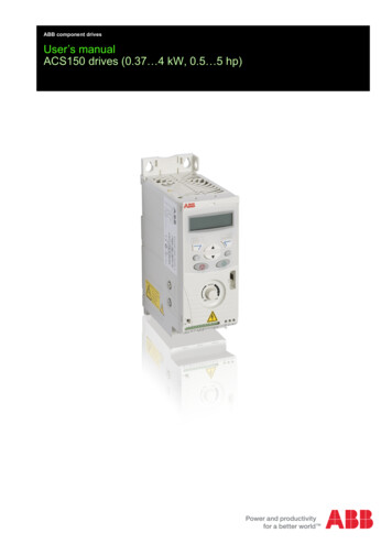
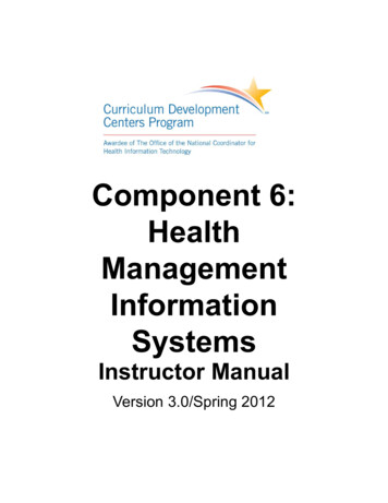
Overview IntroductionThis manual describes the installation, operation, configuration, and specifications of the Hytrol EZLogic accumulationsystem. Please read this material carefully to familiarize yourself with the system and its operation.What is EZLogic ?EZLogic , or Electronic Zero-pressure Logic, is a method of zero-pressure control that combines the sensing accuracy ofphoto-electrics with discrete electronic logic control without the use of a PLC or pneumatic logic components. This systemprovides all the “intelligence” needed to accurately control the various functions of zero-pressure accumulation on a varietyof conveyor models. Reduced noise, higher reliability, higher throughputs, and ease of maintenanceare just some of the advantages of the EZLogic system.The heart of the EZLogic Accumulation System is the EZLogic zone controller. Each controller isequipped with a photoelectric input device to detect product presence, a microprocessor to evaluatevarious input signals, and control connections to provide communication of data between zones andto and from outside sources. Two types of product sensing are available: A retro-reflective type whichis used in conjunction with a reflector to detect packages by looking across the width of the conveyor,and a diffuse type which is used to detect packages when a reflector cannot be used.Figure 1—EZLogic Zone Controller Features of the EZLogic Accumulation SystemThe following is a brief description some of the features of the EZLogic accumulation system. These features are describedin more detail later in this manual.Zero-pressure accumulation of productThis is the primary function of the EZLogic system. Cartons or pallets may be stopped on the conveyor without the buildup of line pressure.Operational modesThe EZLogic system provides two primary modes of operation: singulation mode and slug mode. Singulation mode maybe further configured to operate in fixed zone length mode or dynamic zone allocation mode.Sleep featureConveyor zones that have not seen any carton activity for a selected period of time may be set to “go to sleep,” or stopdriving, until activity is detected, reducing system noise and component wear and reducing energy consumption.Local and remote inputs and outputsInputs to control carton release, operational modes, etc, may be wired to any EZLogic zone controller in the system.Additionally, the EZLogic system provides various output options, such as “zone full” and “zone blocked and stopped,”that may be accessed locally. Control inputs and outputs may also be connected in one central location to interface withcontrollers remotely using the IOP control wiring system.4
Plug-in connections and “snap-together” mountingEZLogic zone controllers, cordsets, and accessory components are all provided with sealed plug-in connectors forrobustness and true “plug and play” convenience. In addition, controllers and auxiliary components snap to the conveyorwithout tools, allowing for quick installation and component replacement.Jam protectionWhen the conveyor is set to run in “slug mode,” if a carton becomes jammed on the conveyor, EZLogic will detect the jamand accumulate cartons upstream from the jam. This prevents product pile-up until the jam is cleared.Special functionsThe EZLogic system also offers many special functions. Some of these enhance product flow, such as the cascadedrelease function, while others are designed to reduce the need for external controls, such as the indexing zone stop andloading and unloading functions.Easy configuration optionsThe EZLogic system comes pre-configured with the most common settings for your particular conveyor model. EZLogic zone controllers may be configured to meet the needs of your system using the EZLogic pushbutton programmer, or byusing a computer and Hytrol’s “Genesis Configuration Manager” software. Genesis Configuration Manager also allowsthe user to save and retrieve configurations, retrieve diagnostic information, and access more advanced options.Once a controller is configured, the configuration from that controller may be copied to other controllers in the system byusing the clone feature of the controller. Description of Operational ModesThe EZLogic accumulation system provides two primary modes of operation for transporting and accumulating product:Singulation mode and slug mode. These modes are described below.Singulation ModeSingulation mode provides individual carton control during transport and accumulation. Each carton is assigned a “zone”as it accumulates on the conveyor. Upon release, the cartons are held in their respective zones until the zone immediatelydownstream is clear. The cartons are thus separated, or “singulated” as they are released and/or transported.There are two ways that EZLogic can assign zones to cartons:Fixed Zone LengthWhen the zone operating mode is set to “fixed zone length” each carton is assigned one mechanical zone (the zone lengthdetermined by the mechanical “build” of the conveyor) as it is transported and accumulated. The zone length must belonger than the longest carton to be conveyed. When cartons are transported or released, a gap equal to the length of onemechanical zone is created between the cartons.Dynamic Zone AllocationWhen the zone operating mode is set to “dynamic zone length” EZLogic uses a process known as “dynamic zone allocation”to adjust the zone length to fit the carton being conveyed.The mechanical zone length (determined by the mechanical “build” of the conveyor) becomes the “base” zone length whenusing dynamic zone allocation. Each carton is assigned enough “base” zones to accommodate its length. For example, ifthe conveyor is built up using 12-inch “base” zones, a 9-inch box will be assigned one “base” zone, or 12 inches, while a21” box will be assigned two “base” zones, or 24 inches. The cartons are thus allocated the proper number of “base” zonesas required by the cartons.5
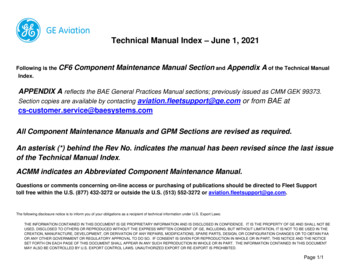
OverviewAs cartons are transported or released, a gap equal to the length of one “base” zone is created between the cartons,regardless of the carton length.Figure 2 — Fixed Zone LengthFigure 3 — Dynamic Zone AllocationSlug ModeSlug mode provides dense accumulation and high throughput when individual carton control is not required. Cartons are notseparated when traveling down the conveyor or when they are released from the conveyor. Zero pressure is still providedduring the accumulation cycle, but only as the cartons arrive at the proper “stopping point.”Figure 4 — Slug Mode6
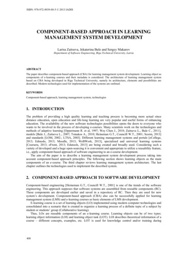
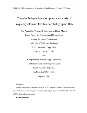
C ompone nt sThe EZLogic accumulation system is made up of several physical components that work together to provide you with asimple, yet powerful control system for your zero-pressure conveyor. These components may be divided into the followingcategories: Main components Auxiliary components Cable components Configuration/diagnostic components Main ComponentsMain Components are those parts of the EZLogic system that are essential for conveyor operation and provide most of thefunctionality of the system. These parts include the zone controller/transducer assembly and the IOP (Input/Output/Power)unit.Zone Controller/Transducer AssemblyThe zone controller/transducer assembly is the heart of the EZLogic accumulation system. There is one assembly locatedin every mechanical zone of any EZLogic -equipped conveyor. It consists of six components: Controller baseCordsetEZLogic zone controllerTransducer (sensor)Retaining Clips (2)Transducer (Sensor)Retaining ClipsCordsetController BaseZone ControllerFigure 5—Zone Controller/Transducer Assembly7
C ompone nt sController BaseThe controller base is the foundation for the other components of the zone controller/transducer assembly. It mounts to theconveyor using either a mounting tab and one fastener or two fasteners. The base provides snap-fit mounting for the cordsetand the zone controller. This allows for easy, fast, and flexible assembly and/or replacement of components.CordsetCordsets provide the power and communications path for EZLogic . There is one cordset per mechanical zone of theconveyor, with the cord length matched to the zone length. Each cordset snaps into a controller base and provides the plugin point for a zone controller. The cordsets connect together in a “daisy-chain” fashion using push-on connections to createthe “power and logic distribution” chain.The cordsets are marked with an arrow indicating the default direction of product flow on the conveyor. They may beinstalled into the controller bases in either a “left hand” or “right hand” orientation. This orientation of the cordsets determinesthe default direction of product flow for the EZLogic system.EZLogic Zone ControllerThe main element of the EZLogic accumulation system is the EZLogic zone controller. The zone controller usesmicroprocessor technology to monitor various inputs from adjacent zone controllers and from outside sources, processthat information based on certain parameters, provide the proper output to control the drive status of the zone, and tocommunicate status information to the other zone controllers.EZLogic zone controllers come in two basic physical variations:Unitized zone controllers have the transducer (sensor) “hard-wired,” or permanently attached. The controller provides themounting point for the transducer, eliminating the need for further mounting hardware.Remote zone controllers do not include the transducer. Instead, a connector is provided to allow the attachment of remotetype transducers. These transducers may be mounted separately from the controller, providing flexibility in various conveyorapplications.In addition to the physical variations above, EZLogic zone controllers are also available in two functional variations:Standard zone controllers provide an extensive function set to meet the needs of most conveyor applications from themost basic to advanced systems. They are identified by the EZLogic logo with yellow background.Figure 6—Unitized Zone ControllerFigure 7—Remote Zone Controller8
Enhanced zone controllers expand on the functionality available in standard zone controllers by providing advancedcommunication and functional capabilities. They are identified by the EZLogic logo with white background.Transducer (Sensor)The transducer is the product-sensing portion of the zone controller/transducer assembly. Commonly called the sensor,current transducers available for the EZLogic GEN3 system are photoelectric devices. Future transducers may incorporateother technologies.There are three sensing types currently available:Polarized reflex, or “retro-reflective” type transducers are used in conjunction with a reflector to detect product. Cartonspassing between the transducer and the reflector interrupt a beam of light. This interruption indicates to the EZLogic controller that a carton is present.Adjustable diffuse transducers detect cartons by bouncing an infrared light beam off of the carton and back to the transducer.These transducers may be used when a reflector interferes with some other operation, such as loading or unloading. Thesensitivity of adjustable diffuse transducers may be adjusted to best detect cartons without detecting objects away from theconveyor.Narrow-beam diffuse transducers are specially designed to be able to “look” through a narrow space, such as betweenrollers spaced closely together. These transducers are designed to detect cartons near them, and are not adjustable.There are two mounting styles available for transducers:Unitized transducers are “hard-wired,” or permanently attached to a zone controller. The zone controller provides themounting point for the transducer.Remote transducers are designed to mount separately from the zone controller. They plug to a non-unitized zonecontroller. By using extension cables, a remote transducer may be mounted several inches away from the zone controllerif necessary.A special type of remote transducer incorporates a tee connection to allow for dual transducer operation. These transducersmay be used to reliably sense oddly shaped or sized objects, or as “problem solvers” in other applications.All transducers are mounted in brackets that provide alignment adjustment in both vertical and horizontal directions, makingprecise sensor alignment and special angled mountings possible.All transducers are mounted in brackets that provide alignment adjustment in both vertical and horizontal directions, makingprecise sensor alignment and special angled mountings possible.Figure 8—Polarized Reflex Transducer9
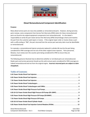
C ompone nt sRetaining ClipsThe retaining clips are used to secure the zone controller to the base by locking the mounting tabs of the base. The clipssimply snap in place over the tabs.IOP UnitThe IOP (Input/Output/Power) unit is a key component of the EZLogic system. The IOP unit performs two tasks: The unit provides power to the other EZLogic components. It converts 100-130 VAC 1ph, or 210-250 VAC 1ph inputpower into the 27 VDC power required by EZLogic .The unit is a hub and controller for the IOP control wiring system. This new concept in controls interfacing providesmany advantages. Please refer to the “EZLogic IOP Solutions” manual for more information.Figure 9—IOP Unit Auxiliary ComponentsAuxiliary ComponentsAuxiliary components provide a way for EZLogic to be interfaced with various external control devices, such as switches,relays, PLCs, etc, to receive control inputs and provide control outputs. The following is a list of available auxiliarycomponents: Auxiliary Input CableAuxiliary I/O ModuleZone Actuation Module (ZAM)Auxiliary Photo-eyesWith the exception of the ZAM, all auxiliary components plug into any EZLogic zone controller through the controller’sauxiliary port.Auxiliary Input CableThe auxiliary input cable is used to provide basic inputs to an EZLogic zone controller. The cable has a connector on oneend that plugs to the auxiliary port of a controller and a two-wire “pigtail” on the other. A connection between these two wiresis interpreted by the zone controller as an “active” input signal. The wires may be connected directly or through any “drycontact” type switching device, such as a toggle switch or relay.10
By default, an “active” input signal is interpreted by the zone controller as a “zone stop” signal and arms the “zone stop”function in that zone. The zone controller may be configured to interpret this input as one of the following signals: Zone Stop (default)Singulate/SlugZone “Wake-Up”“Special Function” InputsEach of these inputs is described later in this manual.Auxiliary I/O ModuleThe auxiliary I/O module is used to provide additional inputs and outputs to/from an EZLogic zone controller. The modulehas two cables. One cable has a connector that plugs to the auxiliary port of zone controller. The other cable ends in a sixwire “pigtail.” These wires may be connected to external control devices to achieve the various I/O options.The auxiliary I/O module can accept two types of input signals:Standard (dry contact) type input is identical to the input accepted bythe auxiliary input cable. Any “dry contact” type signal source, such as atoggle switch or relay, may be used to provide this input signal. No powersource is required to operate this input.Figure 10—Auxiliary I/O ModuleIsolated (voltage) type input will accept a voltage signal as an inputto the zone controller. Many PLCs send voltage signals to devices theycontrol. By using the isolated (voltage) type input option the auxiliaryI/O module provides, extra relays or expensive “relay type” PLC outputcards can be avoided. This input operates on an 18-30 VDC signal.Both types of input signals accepted by the auxiliary I/O module areinterpreted by a zone controller as “zone stop” signals by default. Thezone controller may be configured to interpret this input as any of the signals listed for the auxiliary input cable.In addition to the input options listed above, the auxiliary I/O module can provide a “solid state relay” output from a zonecontroller to an external device. Up to 30 VDC, 80mA current can be passed through this contact output to signal a PLCor other device.By default the EZLogic zone controller provides a basic “photo-eye” (transducer) status output through the auxiliary I/Omodule. The zone
using a computer and Hytrol’s “Genesis Configuration Manager” software. Genesis Configuration Manager also allows the user to save and retrieve configurations, retrieve