Transcription
Errata SheetThis Errata Sheet contains corrections or changesmade after the publication of this manual.Product Family:DL305Manual NumberD3-DCU-MRevision and Date1st Edition, Rev. A; June, 1998Date:August 2022August - 2022D3-232-DCU has been discontinued by manufacturer with no replacement. Please consider the PRODUCTIVITY, BRX or CLICKSeries of PLCs as a replacement.Change to Page 15. Address SwitchThe second sentence in the Address Switch section is incorrect. There is no BCD (Binary Coded Decimal) involved with theaddressing.Instead of “The decimal address is set in BCD (Binary Coded Decimal) format with valid addresses from 1 to 90 decimal.” thesentence should be:“The decimal address is set from 1 to 90 decimal.”Change to Page 19. TroubleshootingFor the “DIAG off” entry in the troubleshooting table, the cause listed is “DCU is defective”. Two other possible causes are adefective CPU module or base.Page 1 of 1
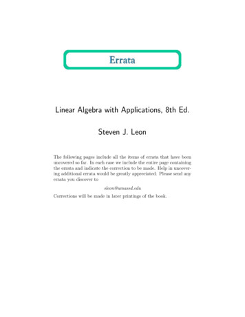
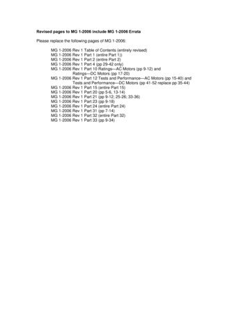
111IntroductionIs this the rightmanual for you?DCU HardwareOverviewThis manual is designed to allow you to quickly install your DL305 DataCommunications Unit (DCU). This is the only manual you will need if your are usingthe DCU as an interface for the Direct SOFT programming package or, as acommunications port for an operator interface. If you plan on using the DCU as aslave interface on a DirectNET network, you should read the DirectNET manualfirst. The DirectNET manual provides detailed descriptions of the networkconfiguration and protocol that is necessary to control communications with theDCUs.The following diagram shows the major DCU components. The address selectionswitches and the communication dipswitches are of special importance. Also, thereare two versions of the DCU RS232C and RS422. You can use RS232C/RS422converters with these units, but it is generally easier to use the version that is bestsuited for your application.On when PLC is inRun ModeOn when PLC batteryneeds replacingOn (flashing) when data isbeing transmittedRUNDATABATTDIAGCPUPWROn when a fatel errorhas occured in the CPU.On when internal diagnostic testshave complete and passed.On when base power is on. If an externalpower supply is used, both base powerand the external supply must be providedfor this indicator to be on.Online/Offline SwitchRS232C/RS422Communication Port Handheld ProgrammerConnectorDCU UsesDIP Switches for communicationsand Protocol ParametersThe DL305 Data Communications Unit (DCU) is a communications interface for theDL305 family of Programmable Logic Controllers (PLCs). This module is primarilyused for two reasons.S As a general purpose communications port to connect a personalcomputer or operator interface.S As a network interface to a DirectNET network.The following pages provide an overview of these uses, along with the informationyou need to connect the DCU.
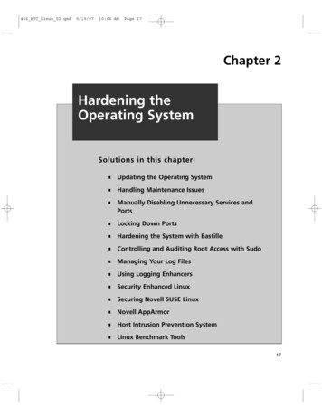
2How can I use the DCU?As a GeneralPurposeCommunicationPortAs a communication port, you can connect various devices, such as operatorinterfaces or personal computers.Since the DCU does not require any programming, you can simply set the DCUcommunication parameters, connect the appropriate RS232C or RS422 cables,and start programming or transferring data.DL305 with DCU
3As a DirectNETInterfaceThe DCU can be used as a network interface for applications that require data to beshared between PLCs, or between PLCs and an intelligent device (such as a hostcomputer). The DCU easily connects to DirectNET. This network allows you toupload or download virtually any type of system data including Timer/Counter data,I/O information, and Register memory information.As part of a PLC Network Slave — The DCU can only be used in a DL305 PLCstation that is serving as a network slave station. In this case, the DCU “listens” to thenetwork for any messages that contain the DCU’s address. The DCU deciphers thenetwork commands, carries out the request to read or write data, and sendsconfirmation and/or information to the master station.DirectNET SlavesSlaves respond tothe master’s requestDirectNET MastersResponseorRequest33
4How can I connect the DCU? – Four Simple StepsComplete the following steps to connectthe DCU.CableSTEP 1. Build the communication cablethat fits your needs.Set the SwitchesSTEP 2. Set the DCU switches. (Baudrate, parity, etc.)STEP 3. Install the DCU.STEP 4. Verify correct operation.Install the DCUCheck the LEDs
5Step 1: Build the communication cableThings to Consider There are several considerations that help determine the type of cable needed foryour DCU application.1. Will the DCU be physically connected in a point-to-point configuration ormulti-drop configuration?2. What electrical specification is best for your application? RS232C orRS422?3. What is the cable schematic?4. What are the relevant cable specifications?5. What installation guidelines are necessary?6. Do you just need a quick test cable?The next few pages discuss these considerations in detail. If you already know thetype of cable that is needed, the cable schematics are included on pages 8 and 9.55
6Consideration 1:PhysicalConfigurationDepending on the version of DCU you have, you can use the DCU in either apoint-to-point or multi-drop configuration. A point-to-point connection only has twostations, a master and a slave. Use the point-to-point configuration to connect apersonal computer, an operator interface, or an intelligent device to a single DCU.You should also use this configuration when you want to connect a DirectNETmaster station to a single DirectNET slave station.Use the multi-drop configuration to connect one master to two or more slaves.Point to PointDL305 with DCUDL405 MasterDL305 PLC SlaveDCUDCM
777Consideration 2:ElectricalSpecificationRS232C or RS422There is a specific model of DCU for both RS232C and RS422 communication. Yourapplication and configuration choice will help determine which electricalspecification is best for you. If you are using multi-drop, you should use RS422. (Youcan use RS232C/RS422 converters if necessary.) If you are using point-to-point,you may have a choice between RS232C and RS422.You can use RS232C if the cable length is less than 50 feet and if the cable will not besubjected to induced electrical noise that is commonly found near welders, largemotors, or other devices that create large magnetic fields.You should use RS422 for all other applications. RS422 allows longer cabledistances (up to 3300 feet) and provides higher noise immunity.Multi-dropDirectNETMastersDirectNET SlavesorDCMThe following diagram shows the port pinouts for the two types of DCUs.D3–232–DCU Port Pinouts114D3–422–DCU Port PinoutsPinSignal DefinitionPinSignal DefinitionPinSignal DefinitionPinSignal Definition1Not connected14Not connected1Not connected14RS422 data out 2RS232C TXD15Not connected2Not connected15RS422 data out –3RS232C RXD16Not connected3Not connected16RS422 data in –4RS232C RTS17Not connected4Not connected17RS422 data in 5RS232C CTS18Not connected5Not connected18Not connected6Not connected19Not connected6Not connected19Not connected7Logic ground 0v20Not connected7Logic ground 0V20Not connected8Not connected21Not connected8Not connected21Not connected9Not connected22Not connected9Not connected22RS422 data out 10Not connected23Not connected10RS422 RTS 23RS422 data out –11Not connected24Not connected11RS422 RTS –24RS422data in –12Not connected25Not connected12RS422 CTS 25RS422 data in 13Not connected13RS422 CTS –
8Consideration 3:Cable SchematicsThe following cable schematics are appropriate for most applications. You may haveto combine some of these examples to design a cable that meets your exactapplication requirements.DL405DL405 DCM to DCU (RS232C)DL305 DCUABDL305A DCMMaster23457TXDRXDRTSCTSGNDB DCUSlave32457RXDTXDRTSCTSGNDDL405 DCMPCPersonal Computer to DCU (RS232C)DL305 DCUADL305AMasterB23514678TXDRXDGNDDCDDTRDSRRTSCTSB 5AMaster327456820RXDTXDGNDRTSCTSDCDDTRDSRB DCUSlave23745TXDRXDGNDRTSCTS25–pinConnectorDL405 DCM to DCU (RS422)DL405DL305 DCUABDL405 DCMDL305A DCMMasterB DCUSlave710111213GND RTS–RTS CTS–CTS710111213GND RTS–RTS CTS–CTS14151617 OUT–OUT–IN IN17161514 IN–IN–OUT OUT
999Multi-drop, DL405 DCM to DL305DCU andDL405PLC Slaves (RS422)A DL405DCMB DL305DCUMasterSlaveADL405DCMCDL305DCUSlaveDL405D CPUPortSlave710111213GND RTS–RTS CTS–CTS710111213GND RTS–RTS CTS–CTS710111213GND RTS–RTS CTS–CTS719181123GND RTS–RTS CTS–CTS14151617 OUT–OUT–IN IN17161514 IN–IN–OUT OUT17161514 IN–IN–OUT OUT9101614 IN–IN–OUT OUT22232425 OUT–OUT–IN IN25242322 IN–IN–OUT OUT25242322 IN–IN–OUT OUTTermination Resistors*BDL305DCUCDL305DCUDL405D CPU PortMulti-drop, PC to DL305DCU and DL405PLCSlaves (RS422)AMasterA23514678PCTXDRXDGNDDCDDTRDSRRTSCTSC DL305DCUD DL305DCUFA–UNICON Convertor SlaveSlave3272025BRXDTXDGNDDTR 5VBDL405E CPU PortSlave710111213GND RTS–RTS CTS–CTS710111213GND RTS–RTS CTS–CTS710111213GND RTS–RTS CTS–CTS719181123GND RTS–RTS CTS–CTS14151617 OUT–OUT–IN IN17161514 IN–IN–OUT OUT17161514 IN–IN–OUT OUT9101614 IN–IN–OUT OUT25242322 IN–IN–OUT OUT25242322 IN–IN–OUT OUTTermination Resistor*Termination Resistor*CDL305DCUDDL305DCUDL405E CPUPortRS422 Multi-drop requires termination resistors (see installation)
10Consideration 4:CableSpecificationsAlthough many types of cables may work for your application, we recommend youuse a cable that is constructed to offer a high degree of noise immunity. A cableconstructed equivalent to Belden 9855 should be sufficient. The followingspecifications should be used as a guideline.Structure . . . . . . . . . . . . . . . . . . . . . . . Shielded, twisted-pair(RS232C only uses two wires and a ground)Conductor size . . . . . . . . . . . . . . . . . . 24 AWG or largerInsulation . . . . . . . . . . . . . . . . . . . . . . . PolyethyleneShield . . . . . . . . . . . . . . . . . . . . . . . . . . Copper braid or aluminum foilImpedance . . . . . . . . . . . . . . . . . . . . . . 100W @ 1MHzCapacitance . . . . . . . . . . . . . . . . . . . . 60pf / meter or lessConsideration 5:InstallationGuidelinesYour company may have guidelines for cable installation. If so, you should checkthose before you begin the installation. Here are some general things to consider.S Don’t run cable next to larger motors, high current switches, ortransformers. This may cause noise problems.S Route the cable through an approved cable housing to minimize the riskof accidental cable damage. Check local and national codes to choosethe correct method for your application.S Consider redundant cabling if the application data is critical. This allowsyou to quickly reconnect all stations while the primary cable is beingrepaired.Cable Shield Grounding — It is important to ground the cable shield to minimizethe possibility of noise. The preferred method is to connect one end (preferably thereceiver end) of the cable shield to the connector housing. If noise problems are stillpresent and you have a good earth ground for the cabinet, you should connect oneend of the shield to the cabinet earth ground. Don’t ground both ends of the shieldbecause this will create induced noise on the cable.ÎÎÎÎÎÎÎÎÎÎStep 1: Strip back about 2.5” of the shield.2.5”Step 2: Crimp a ring connector onto the shield.Step 3: Secure the shield to theconnector shell.
111111Multi-drop Termination Resistors — It is important you add termination resistorsat each end of the RS422 line. This helps reduce data errors during datatransmission. You should select resistors that match the cable impedance. Forexample, a typical 22 AWG solid conductor cable with 4.5 twists per foot has a typicalimpedance of about 120W.There are two ways to actually connect the resistors.S Line-to-Line — this method balances the receive data lines (IN andIN–) and requires one resistor at each end of the line. (The cablediagrams we’ve provided show this method, but you can use either.)S Line-to-Ground — this method also balances the receive data lines, butcommon mode noise rejection is improved significantly. This methodrequires two resistors at each end of the line. Also, since there are tworesistors, the sum total of both resistors should match the cableimpedance.The following diagram illustrates the two options.Line-to-Line TerminationMasterTerminateat Master120 ohmResistorSlaveLast Slave710111213GND RTS–RTS CTS–CTS719181123GND RTS–RTS CTS–CTS14151617 OUT–OUT–IN IN9101614 IN–IN–OUT OUT22232425 OUT–OUT–IN IN120 ohmResistorLine-to-Ground TerminationMasterTerminateat Last SlaveSlaveLast Slave710111213GND RTS–RTS CTS–CTS719181123GND RTS–RTS CTS–CTS14151617 OUT–OUT–IN IN9101614 IN–IN–OUT OUT22232425 OUT–OUT–IN IN62 ohmResistors62 ohmResistors
12Consideration 6:PLCDirect offers a Universal Cable Kit (part number FA–CABKIT). This cable kitA Quick Test Cable allows you to connect various types of DirectLOGIC products with an RS232Ccable in a matter of minutes. The kit consists cable (phone cable with male plugsalready attached) and several specially wired connectors. The special connectorsare a D-sub style with built-in female phone jacks. The kit includes a wide variety ofthe special connectors so you can use one kit to easily connect products from thedifferent DirectLOGIC family of products. To use the kit with the DCU, just followthese steps.1. Plug the appropriate D-sub connector onto the DCU.2. Plug the appropriate D-sub connector onto the other device you areconnecting to the DCU.3. Connect the 50 foot cable to the two D-sub connectors.WARNING: This cable is suitable for quick testing situations and should notbe used in actual applications. This cable is not shielded and is highlysusceptible to electrical noise. Electrical noise can cause unpredictableoperation that may result in a risk of personal injury or damage to equipment.Use the cable specifications described earlier in this manual to select a cablesuitable for actual applications.Build A Test Cable In 30 Seconds1.2.3.Attach Universal Cable Adapter to the DCUAttach another Universal Cable Adapter to theDevice which will connect to the DCUAttach the Universal Cable9 PinUniversal 9 pinD–sub connectorUniversal 25 pinD–sub connector
131313Step 2: Set the DCU switchesThe device(s) connected to the DCU will help you determine the appropriate switchsettings.Host Computer orOperator InterfaceConnectionIf you’re connecting the DCU to a computer or operator interface, just set the DCU tomatch those communication parameters. Check the documentation that came withyour computer or operator interface to determine the available communicationparameters.You’ll need to know the following things.S Baud rateS Parity settingsS ProtocolNOTE: Some operator interfaces support multiple protocols. Make sure youroperator interface uses one of the following protocols.S DirectNET (DL330, DL340, D3–232–DCU, or D3–422–DCU)S Hostlink (TIt or Simaticr TI325, –330, -335, 305–03DM, or 305–02DM)DirectNET Interface The DCU can only be used as a slave station, so set the switches to match thecommunications parameters for the master station.ConnectionDL405 PLC Master - Slave NetworkDCM as MasterDL305 DCU as Slave
14DCUSwitch SettingsThere are two banks of switches located on the side of the DCU that are used to setthe communications and protocol parameters. The following diagram shows thelocations and setting options.ON OFFASCII ModeBlock187654321Not UsedPGM Mode at power up10 ms Delay TimeSelf TestBlock2ODD ParityBlock 1HEX ModeNot usedRun Mode at power upNo DelaySet to OFFNO ParityBaud RateSwitch PositionsBaud12300 OFF OFF1200 ON OFF9600 OFF ON19200 ON ON Baud Rate: The first two positions on block 1 are used to set the baud rate for theDCU. There are four baud rate selections available ranging from 300bps to19.2Kbps. All stations must have the same baud rate before the communications willoperate correctly. Usually, you should use the highest baud rate possible unlessnoise problems appear. If noise problems appear, try reducing the baud rates.Parity: Position 3 on block 1 selects between the two parity options, odd or none. Ifyou’re using all DirectLOGIC equipment, you can use odd parity. Odd parity useseleven bits total (1 start bit, 8 data bits, 1 stop bit, and 1 parity bit.) Some devicesrequire no parity, which uses only 10 bits (1 start bit, 8 data bits, and 1 stop bit.)Self-Test: Position 4 on block 1 selects the factory self-test and should always beswitched off. If the self-test is on, the DCU will not operate correctly.Response Delay Time: Position 5 on block 1 sets the response delay time. Thissets how long the DCU will wait before it responds to each component of aDirectNET communication request. If you’re using all DirectLOGIC equipment, aresponse delay is not required and you should turn off the switch.The DCU may respond too quickly for some devices, such as telephone or radiomodems. If you encounter this problem, turn on the delay switch to provide a 10 msdelay. If this still does not work, check your device manual to see if the devicerequires more than a 10 ms delay.Mode at Power-up: Position 6 on block 1 allows you to select the CPU operatingmode when system power is supplied. If the switch is turned on, the CPUautomatically enters Program mode when power is supplied. If the switch is off, theCPU automatically enters Run mode when power is supplied.ASCII / HEX Mode: Position 8 on block 1 selects between ASCII and HEX modes ofdata representation. If you want the fastest communication possible, use HEXmode. The difference is in the way the data is represented. The same data is twice aslong in ASCII format, so if there’s more data, it takes longer to transfer. If you have adevice on the network that requires ASCII mode, then set the switch for ASCII mode,otherwise, use HEX mode.
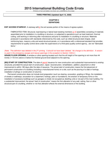
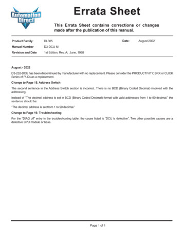
151515Online / OfflineSwitchAs you examined the diagrams at thebeginning of this manual you may have noticedyou can still connect a Handheld Programmereven when there is a cable connected to theDCU. There’s an Online/Offline switch on theside of the unit that determines whichconnection has control of the CPU.In the Offline position, this switch logicallydisconnects the DCU from the network (just asif you pulled the cable from the 25-pinconnector.) Once this switch is moved to theOffline position, the DCU will not communicatewith the network, and the HandheldProgrammer can communicate with the CPU.If you move the switch to the Online position,the DCU will communicate with the network,but not until the master sends a request forcommunication. This does not operate like thereset switch on many personal computers. NOTE: You cannot use the HandheldProgrammer if the switch is in the Onlineposition.ONAddress SwitchThe highlightedsentence is incorrect.It should read: "Thedecimal address is setfrom 1 to 90 decimal.The DCU station address is set by the secondswitch block, which is located on the side ofthe unit. The decimal address is set in BCD(Binary Coded Decimal) format with validaddresses from 1 to 90 decimal. For example,to set an address of 10, you should turn onswitches 4 and 2.The addresses do not have to be sequential,but each station must have a unique address.NOTE: The DCU address switch settings areonly read at power up. If you’ve want tochange the address and the DCU is alreadyup and running, you’ll have to cycle thesystem power to initialize the change.OFF87654321Block 2(Binary Value)Not used6432168421
16Step 3: Install the DCU and start the communicationsCheck the PowerBudgetThe DCU requires 500 mA of 5V base power. Make sure you will not exceed theavailable base power budget by installing the DCU.WARNING: Exceeding the base power budget may cause unpredictablesystem operation that can result in personal injury or equipment damage. Seethe DL305 User Manual for details on power budget calculations.On the back of the DCU is a switch to select if it will receive power form the base(INT – internal position) or from an external power source (EXT – external position).If there appears to be a power budget problem, use the external power sourceoption. The DCU is shipped with a three pin pigtail which should be used to connectthe external power source. The pigtail connects to the bottom outlet on the side of theDCU.PWREXTINTSetSwitchto reflectpowersourceGreen Black White(G) (OV) (5V)If you use an external power supply, you must provide an external groundconnection for the DCU. The following diagram shows how the external powersources are connected.To host orslave stationTwisted Pair5VPowerSupply-5VPowerSupply GND 5VPowerSupply RS422/422 Amp orRS422/432 Convertor
17Install the DCU1717Use the following procedures to install the DCU.WARNING: Always disconnect the system power before installing orremoving any system component. Also, do not install a DCU while the CPU isin RUN mode. This may cause unpredictable operation which can result in arisk of of electrical shock, personal injury, or equipment damage.1. Set the power source switch, locatedon the rear of the DCU, to the correctposition.2. Carefully align the connector on therear of the DCU with the CPUconnector and gently push the DCUonto the CPU. (If the connectors are notaligned properly, you can bend theconnector pins.)3. Secure the DCU to the system with thetwo mounting screws.Connect theCablesMake sure you have all the cables connected and that all the network devices havethe same communication parameters (baud rate, parity, etc.)If you’re using anOperator Interfaceor Computer.Connect the cables and follow the procedures outlined in the documentation thatcame with your host computer software or operator interface. You’ll have to executeyour host or operator interface program before the communications can begin. Forexample, if you’re using DirectSOFT, you can just specify the station address andstart working!If you’re usingDirectNET.Since you can only use the DCU in a slave station, there has to be a network masterthat issues the communication requests. The PLC master station must contain anRLL communications program . (See the DirectNET Manual or the DL405 UserManual for details on the RX and WX instructions.) The master station CPU must bein Run mode in order to execute the communications program. The slave stationCPUs do not absolutely have to be in Run mode because the DCU will still transferthe data. Whether you put the slave stations in Run mode depends on yourapplication requirements.
18Step 4: Verify that it’s working correctlyCheck the DCU indicators to verify the DCU is operating correctly. The followingdiagram shows the proper indicator conditions.On when PLC is inRun ModeOn when PLCbattery needsreplacingOn when a fatelerror has occured inthe CPU.RUNDATABATTDIAGCPUPWROn (flashing) whendata is beingtransmittedOn when internaldiagnostic tests arecomplete and havepassed.On when basepower is on. If anexternal powersupply is used, bothbase power and theexternal supply mustbe provided for thisindicator to be on.
191919TroubleshootingIf the DCU does not seem to be working correctly, check the following items.1. Cable and connections. Incorrectly wired cables and loose connectorscause the majority of problems. Verify you’ve selected the proper cableconfiguration and check to see the cable is wired correctly.2. Dipswitch settings. Make sure you’ve set the DCU to match thecommunication parameters required by the master station (DL405 DCM,operator interface or host computer).3. Incorrect protocol. Make sure your operator interface or personal computersoftware can use the Direct NET, Hostlink/CCM2 protocol.4. Communications program. Check the communications program for errors.Consult the DirectNET Manual or the manuals that came with your hostcomputer software or operator interface for details.The following table provides additional troubleshooting details.Indicator StatusPWR offFor "DIAG off", twoother possible causesare a defective CPUmodule or base.Possible CauseCorrective ActionPLC power is disconnectedDCU is not connected to the CPUproperlyCheck the PLC source power.Make sure the DCU is securelyfastened to the CPU and noconnector pins are bent.Check the external power source.DCU external power source(if used) is not connectedDCU is defectiveReplace the DCUDIAG offDCU is defectiveReplace the DCUDATA does not flash duringcommunicationsLoose or incorrectly wired cableOnline / Offline switch is in theOffline positionCommunications program is notcorrectCheck the cable connections andpinouts.Set the switch to Online.Check the mastercommunications program. Verifythe address, amount of data, anddata type are correct.
ng Temperature . . . . . . . . . . . . . . . . .Storage Temperature . . . . . . . . . . . . . . . . . . .Operating Humidity . . . . . . . . . . . . . . . . . . . .Air Composition . . . . . . . . . . . . . . . . . . . . . . .Vibration . . . . . . . . . . . . . . . . . . . . . . . . . . . . . .Shock . . . . . . . . . . . . . . . . . . . . . . . . . . . . . . . .Voltage Isolation . . . . . . . . . . . . . . . . . . . . . . .Noise . . . . . . . . . . . . . . . . . . . . . . . . . . . . . . . .OperatingSpecificationsPower Budget Requirement . . . . . . . . . . . . . 500 ma @ 5 VCommunication InterfaceD3–232–DCU . . . . . . . . . . . . . . . . . . . . . . Serial RS232C, half-duplex, DTE,Asynchronous, 8 bits/characterD3–422–DCU . . . . . . . . . . . . . . . . . . . . . . Serial RS422, Half-duplex,Asynchronous, 8 bits/characterBaud Rates . . . . . . . . . . . . . . . . . . . . . . . . . . . 300 to 19.2K baud, switch selectableMaximum Distance . . . . . . . . . . . . . . . . . . . . 3300 feet (1000 meters) RS42250 feet (18 meters) RS232CProtocol . . . . . . . . . . . . . . . . . . . . . . . . . . . . . . DirectNET, also compatible withHostlink/CCM2Diagnostics . . . . . . . . . . . . . . . . . . . . . . . . . . . Automatic check ofcommunications, switch settings,and LEDs32 to 140 F (0 to 60 C )–4 to 158 F (–20 to 70 C )5 to 95% (non-condensing)No corrosive gases permittedMIL STD 810C 514.2MIL STD 810C 516.21500 VAC, 1 minute durationNEMA ICS3–304
Errata Sheet Page 1 of 1 Product Family: DL305 Manual Number D3-DCU-M Revision and Date 1st Edition, Rev. A; June, 1998 Date: August 2022 This Errata Sheet contains corrections or changes made after the publication of this manual.