Transcription
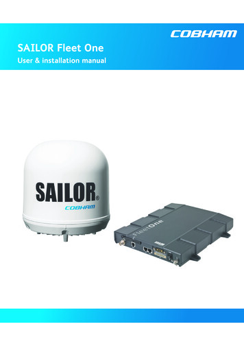
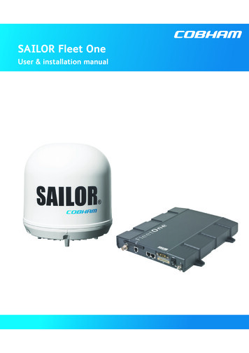
SAILOR Fleet OneUser & installation manual
Document number: 98-141368-BRelease date: 7 April 2015DisclaimerAny responsibility or liability for loss or damage in connection with the use of this product and theaccompanying documentation is disclaimed by Thrane & Thrane A/S. The information in this manual isprovided for information purposes only, is subject to change without notice and may contain errors orinaccuracies. Manuals issued by Thrane & Thrane A/S are periodically revised and updated. Anyonerelying on this information should acquire the most current version e.g. from com, Service and support, or from the distributor. Thrane &Thrane A/S is not responsible for the content or accuracy of any translations or reproductions, in whole orin part, of this manual from any other source. In the event of any discrepancies, the English version shallbe the governing text.Thrane & Thrane A/S is trading as Cobham SATCOM.Copyright 2015 Thrane & Thrane A/S. All rights reserved.Trademark acknowledgements: SAILOR is a registered trademark of Thrane & Thrane A/S in the European Union, the United Statesand other countries. Windows is a registered trademark of Microsoft Corporation in the United States and othercountries. Inmarsat is a registered trademark of International Maritime Satellite Organisation (IMSO) and islicensed by IMSO to Inmarsat Limited and Inmarsat Ventures plc. Inmarsat’s product names are trademarks or registered trademarks of Inmarsat. Other product and company names mentioned in this manual may be trademarks or trade names oftheir respective owners.Company web sitewww.cobham.com/satcom98-141368-Bii
Safety summary1The following general safety precautions must be observed during all phases of operation, serviceand repair of this equipment. Failure to comply with these precautions or with specific warningselsewhere in this manual violates safety standards of design, manufacture and intended use of theequipment. Thrane & Thrane A/S assumes no liability for the customer's failure to comply withthese requirements.Observe marked areasUnder extreme heat conditions do not touch areas of the terminal orantenna that are marked with this symbol, as it may result in injury.Microwave radiation hazardsDuring transmission the antenna in this system radiates MicrowavePower.This radiation may be hazardous to humans close to the antenna.During transmission, make sure that nobody gets closer than the recommended minimum safetydistance.On the SAILOR Fleet One, the minimum safety distance to the antennapanel on the focal line is 0.6 m, based on a radiation level of 10 W/m2.The radiation level is 100 W/m2 at a distance of 0.2 m from theantenna panel. Refer to the drawing below.Pour une antenne SAILOR Fleet One, la distance de sécurité minimaleavec le panneau de l'antenne sur l'axe focal est de 0.6 m, sur la base d'unniveau de radiation émis de 10 W/m2. L'appareil génère un niveau de radiation de 100 W/m2 à unedistance de 0.2 m de l'avant du panneau de l'antenne. Veuillez consulter le schéma au-dessous.MICROWAVE RADIATIONNo personnel within safety distanceSafety distance:0.6 m, 10 W/m20.2 m, 100 W/m260 Distance to other equipmentDo not move the antenna closer to radars than the min. safe distance specified in the installationmanual - it may cause damage to the antenna.98-141368-Biii
Compass Safe Distance:SAILOR Fleet One terminal: min. 0.3 m.SAILOR Fleet One antenna: min. 1.2 mServiceUser access to the interior of the system units is prohibited. Only a technician authorized byCobham SATCOM may perform service - failure to comply with this rule will void the warranty.Do not service or adjust aloneDo not attempt internal service or adjustments unless another person, capable of rendering first aidresuscitation, is present.Grounding, cables and connectionsTo minimize shock hazard, the equipment chassis and cabinet must be connected to an electricalground. The terminal must be grounded to the ship. For further grounding information refer to theInstallation manual.Do not extend the cables beyond the lengths specified for the equipment. The cable between theterminal and antenna can be extended if it complies with the specified data concerning cablelosses etc.All cables for the SAILOR Fleet One system are shielded and should not be affected by magneticfields. However, try to avoid running cables parallel to AC wiring as it might cause malfunction ofthe equipment.Power supplyThe voltage range is 10.5 - 32 V DC; 11.5 A - 4 A. It is recommended that the voltage is providedby the 24 V DC bus on the ship. Be aware of high start-up peak current: 20 A@24 V, 5 ms.If a 24 V DC power bus is not available, an external 115/230 VAC to 24 V DC power supply can beused.Do not operate in an explosive atmosphereDo not operate the equipment in the presence of flammable gases or fumes. Operation of anyelectrical equipment in such an environment constitutes a definite safety hazard.Keep away from live circuitsOperating personnel must not remove equipment covers. Do not replace components with thepower cable connected. Under certain conditions, dangerous voltages may exist even with thepower cable removed. To avoid injuries, always disconnect power and discharge circuits beforetouching them.Failure to comply with the rules above will void the warranty!98-141368-Biv
Related documentsThe below list shows the documents related to this manual and to the SAILOR Fleet One system.Title and descriptionDocumentnumberSAILOR Fleet One, Installation guide98-141370A short guide to installing the SAILOR Fleet One systemSAILOR Fleet One, Quick guide98-141369A short guide to the most important functions of theSAILOR Fleet One systemIP Handset, User manual98-126059Explains the features and functions of the IP Handset. The IPHandset works as a standard IP handset, but also serves as a userinterface for the SAILOR Fleet One system.TypographyIn this manual, typography is used as indicated below:Bold is used for the following purposes: To emphasize words.Example: “Do not touch the antenna”. To indicate what the user should select in the user interface.Example: “Select SETTINGS LAN”.Italic is used to emphasize the paragraph title in cross-references.Example: “For further information, see Connecting Cables on page.”.98-141368-Bv
Table of contentsChapter 1 IntroductionYour SAILOR Fleet One . 1Features and interfaces . 2Main units . 3Tools for setup and use . 4Available services . 4Chapter 2 InstallationUnpack your SAILOR Fleet One . 6Mounting considerations for the antenna . 7Antenna mast design .11Install the antenna .13Mounting considerations for the terminal .16Install the terminal .17Connect cables .21Power cable selection .34Chapter 3 Get startedStart up the SAILOR Fleet One .37Connect a smartphone .39Connect an IP handset .41Connect an analog phone .42Connect a computer .42Make a call .43Connect to the Internet .44Chapter 4 OperationPhone calls .45Data connection .49The built-in web interface .51Dashboard .5498-141368-Bvi
Table of contentsPhone book .57Call log .59SMS messages .60SIM PIN .63Chapter 5 ConfigurationSet up the data connection .67Set up the interfaces .68Select a preferred satellite .73Set coverage restrictions (Geo-fencing) .74Log on as administrator .75Save or load a configuration .78Call charges .79Log handling .80Data limits .80Configure the SIM PIN .81Set up user permissions .83Restricted dialling .84External data connections .86Track the SAILOR Fleet One .88Antenna RF noise filter .90Positioning system .91Chapter 6 Maintenance and troubleshootingGet support .92Update software .93Part numbers .95Troubleshooting guide .96Status signalling .99Generate a diagnostic report .100Event messages .101Extended status .10898-141368-Bvii
Table of contentsAntenna properties .108Self test .109Reset button .110List of reserved subnets .112App. ATechnical specificationsSAILOR Fleet One antenna .113SAILOR Fleet One terminal .117Glossary.121Index.12498-141368-Bviii
Chapter 1Introduction1Your SAILOR Fleet OneCongratulations on the purchase of your SAILOR Fleet One System!SAILOR Fleet One is a maritime broadband system, providing simultaneous high-speed dataand voice communication via satellite, using Inmarsat BGAN (Broadband Global Area Network).Used with a phone or computer the SAILOR Fleet One gives you access to: Internet browsing E-mail Phone services File transfers VPN (Virtual Private Network) access to corporate serversThis chapter has the following sections: Features and interfaces Main units Tools for setup and use Available services98-141368-B1
Chapter 1: IntroductionFeatures and interfacesPhone interfaceWireless deviceLAN interface(PoE)WLAN access pointExternal equipment,e.g. fishery reportingComputerIP handsetThe SAILOR Fleet One system offers the following features and interfaces: Simultaneous voice and data communication over BGAN Full duplex, single or multi-user, up to: 100 kbps Standard Voice (4 kbps) 2 LAN (Local Area Network) ports with PoE (Power over Ethernet) for connectingcomputers, e-hubs, IP handsets, WLAN access point etc. 1 Standard Phone port 1 multi-purpose I/O connector with 5 configurable inputs/outputs 1 SIM slot for your Fleet One SIM card Support for GPS, GLONASS and BeiDou-1 positioning systems Built-in DHCP/NAT router Built-in web interface for managing phone book, messages and calls, and configuration Input power: 10.5 - 32 V DC (11.5 A - 4 A) CE certified ATC resilient Supports Inmarsat’s extended L-band services, Inmarsat-XL98-141368-B2
Chapter 1: IntroductionMain unitsUnits includedThe SAILOR Fleet One system includes the following main units: SAILOR Fleet One antenna SAILOR Fleet One terminal Optional: IP HandsetSAILOR Fleet One antennaThe SAILOR Fleet One system uses the SAILOR Fleet One antenna, which is a small sizemaritime 2-axis stabilized BGAN antenna.For information on how to install the antenna, see Chapter 2, Installation.SAILOR Fleet One terminalThe SAILOR Fleet One terminal is the controlling unit in the SAILOR Fleet One system. Itcontains all user interfaces and a power LED indicator and stores configuration data.98-141368-B3
Chapter 1: IntroductionSIM cardThe terminal has a SIM (Subscriber Identity Module) slot located in the connector panelbehind a small cover plate. The terminal requires a dedicated SAILOR Fleet One SIM card,which you get from your airtime provider.The system requires a SIM card to go online and to access the settings of the terminal.However, using the web interface you can view the Dashboard and upload software withoutinserting a SIM card.Router functionThe SAILOR Fleet One terminal has a router function which routes traffic between the localnetwork connected to the terminal and network connections on the BGAN network.The router contains NAT (Network Address Translation) which allows sharing of a public IPaddress between a number of local network users.Tools for setup and useThe built-in web interface in the terminal is used for easy configuration and daily use. Theweb interface is accessed from a computer connected to the terminal, using an Internetbrowser. No installation of software is needed.For details on the web interface, see The built-in web interface on page 51.The ThraneLINK Management Application (TMA) is a Windows program that providesmonitoring and software update of connected Cobham SATCOM devices with ThraneLINKsupport. The devices must be on the same LAN.If you have an IP Handset (minimum version 1.8) from Cobham SATCOM, it can be used fordisplaying status, accessing a subset of controls and views and entering the PIN code for theterminal. The IP Handset connects to the LAN interface of the terminal. For information onhow to use the IP Handset, see the user manual for the IP Handset (listed in Relateddocuments on page v).Available servicesFleet One is a maritime broadband service providing the following services through theInmarsat BGAN system: Data connection to the Internet. A data connection which several users can sharesimultaneously. The user pays for the amount of data sent and received. Phone connection. A standard phone connection for making calls over the BGANnetwork. SMS. A Short Messaging Service for sending and receiving SMS messages to and from theterminal.Limitations in services: You may have limited access to some services in some areas. Forupdated information, ask your service provider. See also Satellite coverage on page 5.98-141368-B4
Chapter 1: IntroductionAccess to services and interfacesThe following table shows which equipment and connectors you can use to access the serviceslisted in the left column.Connector on terminalServicePhoneDataStandard voiceSMSAnalog phoneLAN (PoE)Computer or WLAN access pointIP handset orsmartphone via WLAN access point-Computer accessing the webinterface of the terminal.Satellite coverageThe coverage map below shows satellite coverage and rate regions for the Fleet One service atthe time of writing. For updated information on coverage, see inmarsat.com.98-141368-B5
Chapter 2Installation2This chapter describes how to install the SAILOR Fleet One antenna and the SAILOR Fleet Oneterminal. It has the following sections: Unpack your SAILOR Fleet One Mounting considerations for the antenna Antenna mast design Install the antenna Mounting considerations for the terminal Install the terminal Connect cables Power cable selectionUnpack your SAILOR Fleet OneUnpack your SAILOR Fleet One system and check that the following items are present: SAILOR Fleet One terminal SAILOR Fleet One antenna DC power cable (1 m) Antenna cable (10 m) Ethernet cable (2 m) I/O connector Mounting bolts and washers for the antenna Kit for water protection of antenna connector joint Installation guide Quick guide CD with Installation guide, Quick guide and User & installation manual Optional: IP HandsetInspect all units and parts for possible transport damage.98-141368-B6
Chapter 2: InstallationMounting considerations for the antennaWhen looking for a place to mount the SAILOR Fleet One antenna, make the followingconsiderations: Do not place the antenna close to large objects that may block the signal. Place theantenna with free line of sight in all directions to ensure proper reception of the satellitesignal. Place the antenna in such a way that persons are not exposed to radiation from theantenna. Keep the minimum safety distance. See Safety summary on page iii. Do not place the antenna within range of other equipment that can interfere with theSAILOR Fleet One. Do not place the antenna close to a funnel, as smoke deposits are corrosive. Furthermore,deposits on the radome can degrade performance. Do not block the drainage gasket in the bottom centre of the antenna. Leave space belowthe antenna to allow any water to escape.The following sections describe the details for the mounting considerations.ObstructionsThe antenna rotates 360 and down to -60 in pitch and roll, to allow for continuous pointingeven in heavy sea conditions. Any objects within this field can cause signal degradation.The amount of degradation depends on the size of the object and the distance from theantenna. As a rule of thumb any object that covers an angle of less than 3 at the antenna haslimited effect. The table below gives a guideline for the distance and maximum size of blockingobjects in order to avoid degradation.98-141368-BDistance of objectMaximum size of object3m16 cm5m26 cm10 m52 cm20 m104 cm7
Chapter 2: InstallationRadiation hazardThe SAILOR Fleet One antenna radiates 16.1 dBW EIRP. This translates to a minimum safetydistance of 0.6 m from the antenna while it is transmitting, based on a radiation level of10 mW/cm2.MICROWAVE RADIATIONNo personnel within safety distanceSafety distance:0.6 m, 10 W/m2(0.2 m, 100 W/m2)60 InterferenceThe antenna must be mounted as far away as possible from the ship’s radar and high powerradio transmitters (including other Inmarsat based systems), because they may compromisethe antenna performance. RF emission from radars might actually damage the antenna.The SAILOR Fleet One antenna itself may also interfere with other radio systems. Especiallyother Inmarsat systems and GPS receivers with poor frequency discrimination are vulnerableto the radiation generated by the SAILOR Fleet One antennas.RadarIt is difficult to give exact guidelines for the minimum distance between a radar and theantenna because radar power, radiation pattern, frequency and pulse length/shape vary fromradar to radar. Further, the antenna is typically placed in the near field of the radar antenna andreflections from masts, decks and other items in the vicinity of the radar are different from shipto ship.However, it is possible to give a few guidelines:Since a radar radiates a fan beam with a horizontal beam width of a few degrees and a verticalbeam width of up to /- 15 , the worst interference can be avoided by mounting the antennaat a different level – meaning that the antenna is installed minimum 15 above or below theradar antenna. Due to near field effects the benefit of this vertical separation could be reducedat short distances (below approximately 10 m) between radar antenna and theSAILOR Fleet One antenna. Therefore it is recommended to ensure as much vertical separationas possible when the SAILOR Fleet One antenna has to be placed close to a radar antenna.98-141368-B8
Chapter 2: InstallationMin. 15 Min. 15 Radar distanceThe minimum acceptable separation (d min.) between a radar and the antenna is determinedby the radar wavelength/frequency and the power emitted by the radar. The tables below showsome “rule of thumb” minimum separation distances as a function of radar power at X and Sband. If the d min. separation listed below is applied, antenna damage is normally avoided.“d min.” is defined as the shortest distance between the radar antenna (in any position) and thesurface of the SAILOR Fleet One antenna.X-band ( 3 cm / 10 GHz) damage distanceRadar powerd min. at 15 d min. at 60 vertical separation vertical separation0 – 10 kW0.8 m0.4 m30 kW2.4 m1.2 m50 kW4.0 m2.0 mS-band ( 10 cm / 3 GHz) damage distanceRadar powerd min. at 30 d min. at 75 vertical separation vertical separation0 – 10 kW0.4 m0.2 m30 kW1.0 m0.5 m50 kW2.0 m1.0 mThe separation distance for C-band (4-8 GHz) radars should generally be the same as for Xband radars.98-141368-B9
Chapter 2: InstallationRadar interferenceEven at distances greater than “d min.” in the previous section the radar might still be able todegrade the performance of the SAILOR Fleet One system.The presence of one or more X-band radars within a radius up to 100 m could cause a minordegradation of the signal-to-noise ratio during high speed and data calls. The degradation willbe most significant at high radar pulse repetition rates.As long as receiving conditions are favorable, this limited degradation is without importance.However, if receiving conditions are poor – e.g. due to objects blocking the signal path, heavyrainfall or icing, low satellite elevation and violent ship movements – the small extradegradation due to the radar(s) could cause poor call quality. A voice call might become noisyor fail while a data connection might decrease in speed and performance.The presence of S-band radar(s) is unlikely to cause any performance degradation – as long asthe minimum distances (d min.) listed in the previous section are applied.It is strongly recommended that interference free operation is verified experimentally beforethe installation is finalized.CAUTION! The antenna must never be installed closer to a radar than “dmin.” - even if experiments show that interference free operation can beobtained at shorter distances than “d min.” in the previous section.Other Inmarsat systemsRecommended minimum safe distance to other Inmarsat antennas is 10 m.GPS receiversGood quality GPS receivers will work properly very close to the antenna - typically down to onemeter outside the main beam, and down to a few meters inside the main beam. However,simple GPS receivers with poor frequency discrimination could be affected at longer range(typically 10 m). It is always recommended to test the GPS performance before the installationis finalized.VSAT systemsFor optimum performance we recommend a minimum distance of 3 meters from the BGANantenna to VSAT antennas.Auxiliary Terrestrial Component (ATC)The SAILOR Fleet One system is resilient to ATC base stations (future terrestrial mobilesystems) that operate inside the Inmarsat band and that may be located near the coast.Other transmittersSee Minimum distance to transmitters on page 115 in Appendix A for minimumrecommended distance to transmitters in the frequency range below 1000 MHz.98-141368-B10
Chapter 2: InstallationAntenna mast designThe antenna mast must be designed to carry the weight of the antenna unit, which isapproximately 3.9 kg ( 1.1 kg for the mast mount kit)The mast must also be able to withstand onboard vibrations and wind forces up to 108 knotson the radome, even in icing conditions.Antenna mast mountingMast mount kit:The top of the SAILOR Fleet One antenna mast should be fitted with the dedicated mountingkit available from Cobham SATCOM.Assemble the mast mount kit according to the assembly instruction included with the kit.The mast mount kit interfaces to a 1½” pipe (OD 48.3 mm). If the supplied plastic sleeve isomitted, a maximum diameter OD of 52 mm can be used.Custom mast mounting:For a custom mast mounting, use 4 M6 bolts (A4) in the threaded bushings on the 175.4 mmdiameter circle in the bottom of the antenna. The length of the bolts must be such that theyengage into the bushings of the radome with min. 6 mm and max. 12 mm.ImportantDo not block the drainage hole in the centre bottom of the antenna.Drill a hole for the cable in the mast flange or use an angled connector.Mast length and diameterThe placement of the antenna must ensure a rigid structural connection to the hull or structureof the ship. Parts of the ship with heavy resonant vibrations are not suitable places for theantenna.A small platform or short mast provides rigid support for the antenna fastening bolts and a rigidinterface to the ship.If it is necessary to use a tall mast, use the table on page 12 to obtain the maximum free lengthof the mast. Note that these values depend on rigid antenna-ship interfaces. The crosssectional properties and the corresponding maximum free length give a natural frequencyabove 30 Hz.It is recommended to shorten the mast length as much as possible to obtain higherfrequencies. Alternatively, mount stays or wires to stabilize the mast further.NoteThe table in the next section lists the values for steel masts.For aluminium masts, the free mast length is reduced to 75% of the values for steel.High masts or installations on ships with high vibration levels should be further stabiliz
On the SAILOR Fleet One, the minimum safety distance to the antenna panel on the focal line is 0.6 m, based on a radiation level of 10 W/m2. The radiation level is 100 W/m2 at a distance of 0.2 m from the antenna panel. Refer to the drawing below. Pour une antenne SAILOR Fleet One, la distance de sécurité minimale
