Transcription
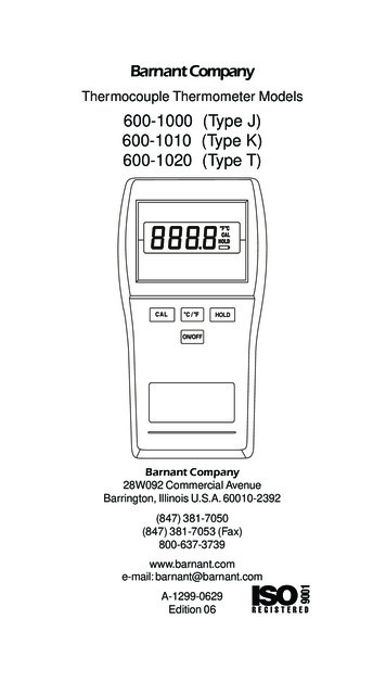
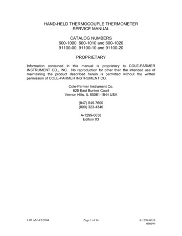
HAND-HELD THERMOCOUPLE THERMOMETERSERVICE MANUALCATALOG NUMBERS600-1000, 600-1010 and 600-102091100-00, 91100-10 and 91100-20PROPRIETARYInformation contained in this manual is proprietary to COLE-PARMERINSTRUMENT CO., INC. No reproduction for other than the intended use ofmaintaining the product described herein is permitted without the writtenpermission of COLE-PARMER INSTRUMENT CO.Cole-Parmer Instrument Co.625 East Bunker CourtVernon Hills, IL 60061-1844 USA(847) 549-7600(800) 323-4340A-1299-0638Edition 039:07 AM 4/5/2004Page 1 of 14A-1299-0638030199
TABLE OF CONTENTSSECTION IFUNCTIONAL DESCRIPTIONBLOCK DIAGRAMSECTION IICIRCUIT DESCRIPTIONSCHEMATIC DIAGRAMREPLACEMENT PARTS LISTSECTION IIITROUBLESHOOTINGSECTION IVCALIBRATION PROCEDUREFUNCTIONAL CHECK9:07 AM 4/5/2004Page 2 of 14A-1299-0638030199
FUNCTIONAL DESCRIPTIONThis Hand-Held Thermocouple Thermometer is a microprocessor-based,precision instrument, for use with any one of J, K or T type thermocouples. Theunit features a large, 0.5-inch high liquid crystal display with annunciators, a fourbutton silicon rubber touch keypad, a splashproof plastic case, and is intrinsicallysafe. Factory calibration is maintained in a non-volatile memory (EEPROM).Readings may be displayed in Fahrenheit or Celsius. A reading ‘Hold’ functionand field calibration for probe offset is also included.BLOCK DIAGRAM9:07 AM 4/5/2004Page 3 of 14A-1299-0638030199
CIRCUIT DESCRIPTIONPlease refer to the schematic diagram (page 9) while reading this circuitdescription.Power SupplyThe power supply circuits perform multiple functions: convert the battery toa steady 3.3V, switch the meter on and off, and provide a reset to themicroprocessor.Power to the meter is supplied by two 1.5-volt Alkaline “AA” batteries. R1provides intrinsic safety current limiting. U1 and its associated circuitry comprisethe power supply. This is configured as a step-up switching regulator with a 3.3V output, and a 1.0 to 3.2 volt input. The 3.3 is applied to Q1, which acts as anelectronic On/Off switch. With the shutdown (“SHDN”) pin connected to theoutput of this switch, whenever the switch is off, U1 enters a standby mode inwhich it consumes less than 1 microamp of current. To activate this circuit, the“On/Off” switch is pressed, which grounds one end of R6. This turns on Q1which in turn brings the shutdown pin of U1 high, thus starting the regulator.With the 3.3 now up, and the “On/Off” switch still held down, the latchformed with U5B and U5C, latches Q2 on. Once this happens, you may thenrelease the “On/Off” switch and the meter will stay on.The output of Q1 has a slow rise time, typically 100 milliseconds. This istoo slow for the microprocessor to reset. Since the low battery input pin (“LBI”) ofU1 is a precision comparator, it is used to sense when the power supply outputhas risen to greater than 2.5 volts. At this point the low battery output pin(“LBO”) goes high, which allows C5 to charge, and complete the microprocessorreset sequence.To switch the power supply off, the microprocessor first senses that youhave again pressed the “On/Off” switch. It then blanks the display and waits foryou to release the “On/Off” switch, at which time it clears port pin R40, whichcauses the U5 latch to toggle, thus turning off Q2, and in turn, Q1.Analog CircuitryThe analog circuits consist of a bias and filter network for thethermocouple, an ambient sensor circuit with linearization, an eight channelmultiplexer, a 1.25-volt voltage reference, and a discrete single slope analog todigital converter (A/D).Since all voltages within this meter must be positive, and since athermocouple may produce a negative output voltage differential, a bias network9:07 AM 4/5/2004Page 4 of 14A-1299-0638030199
is used to keep all thermocouple voltages positive. This is R20 and R23. Lowfrequency filtering is provided by C10, C11 and C12, while high frequencies areattenuated with L3 and L4. The two sides of the thermocouple are connected totwo inputs of the multiplexer.Other inputs to the multiplexer are the reference voltage, the ambientsensor, a battery voltage sense and an offset voltage for the A/D converterprocess.Analog to Digital Converter (A/D)This A/D converter provides 16 bits of resolution ( 1 part in 65,535 ), with aconversion time of 50 milliseconds. It consists of a DC amplifier, windowcomparator, analog integrator, gated clock and the microprocessor.The output of the multiplexer is applied to a DC amplifier, U3A, which hasa fixed gain of 14. This is connected to the upper side of a “window” detector,U4B. U3B forms an analog integrator. Its output is connected to the lower sideof a “window” detector, U4A. Figure 1 shows a typical A/D conversion cycle.“Vin” is the output level at U3A, and has a normal range from 500 mV minimumto 2 V maximum. “VL” is the voltage present at U4A-2, typically 450 mV. TPAgoes low to signify the start of the measuring period, while TPB goes low tosignify the end of the measuring period. The microprocessor counts the clockpulses, at the output of U5D, while the gate is high, but only between T3 and T4.Beginning at T0, the emitter of Q3 is raised high. This allows the output ofthe integrator, U3B, to rise. At T2, when the integrator output crosses the inputlevel, Vin, the microprocessor pulls Q3 emitter low. The delay from T2 until thisoccurs is the small overshoot. As the integrator again crosses the Vin level, atT3, the gate again ‘opens’ and the microprocessor begins counting clock pulses.This continues until T4, the point where the integrator crosses VL. With the ‘gate’closed, the microprocessor reads the number of clock pulses and converts this toa voltage, which is then used for calculating the thermocouple or ambienttemperature or battery voltage.One of these conversions occurs for each multiplexer input. Themultiplexer is switched from one channel to the next at time T4. The total timefrom T0 to T4 is a maximum of 50 mS. There is a 50 mS delay betweenconversions (from T4 to the next T0). This delay allows for the DC amplifier tosettle.9:07 AM 4/5/2004Page 5 of 14A-1299-0638030199
Figure 1.A/D TimingOther FeaturesThermocouple voltages are measured by taking readings of eachthermocouple lead, with respect to ground, and subtracting the two values withthe microprocessor.Calibration information and thermocouple type are stored in the EEPROM.Thermocouple type is determined when the unit is calibrated on the test fixture,which makes connection through the “calibration access port”. Alternately, thereis a “secret” key combination that allows this to be changed:Note: Begin with power off. Press and hold the C/ F and HOLD buttonsand then press On/Off. Wait about 5 seconds until the display shows a singledigit number, 0, 1 or 2. Release the C/ F and HOLD buttons. A “0” represents“K”, “1” represents “J”, and “2” represents “T”. Use the C/ F button to select 0,1 or 2, as required. Press the HOLD button. The selected thermocouple type isnow stored in EEPROM. If different, the front panel label should be changed tomatch this new type.9:07 AM 4/5/2004Page 6 of 14A-1299-0638030199
The liquid crystal display is of the “static” drive type. This means that thedrive voltage is a simple square wave, with levels of 0 and 3V. The result is avery wide viewing angle (as compared to a multiplexed LCD).The microprocessor runs at 2.09 MHZ; this frequency should only bemeasured at U8-2.9:07 AM 4/5/2004Page 7 of 14A-1299-0638030199
9:07 AM 4/5/2004Page 8 of 14A-1299-0638030199
REPLACEMENT PARTS LISTBarnant 11A-4498A-4497B-1079-04689:07 AM 4/5/2004Cole-Parmer 11A-4498A-4497B-1079-0468DescriptionPCB AssyInput Connector AssyScrew, #2-56Lockwasher, #2Case, FrontOverlay, WindowOverlay, “J”Overlay, “K”Overlay, “T”LensLCDZebra StripKeypadCase, BackWire BailBattery ClipsBattery DoorFiber WasherScrew, Battery DoorFoot, BottomPad, BottomScrew, CasePage 9 of 14A-1299-0638030199
SECTION IIITROUBLESHOOTINGThe following is a list of typical problems that might occur and possibleremedies.Does Not Turn On Dead batteries -- replace with new ones. Bad battery connections -- check the clips for spring tension to the PCboard. Batteries installed backwards. On/Off switch not working -- clean switch contacts.“Low Battery” graphic is on. Dead batteries If the batteries are OK, then the EEPROM may have lost calibrationinformation.Error Messages ‘Err’ -- field cal outside of 0 10 C (32 18 F) ‘Err1’ -- EEPROM has lost factory cal info -- recalibrate. ‘Err2’ -- EEPROM has lost stored thermocouple type or bad field cal data-- recalibrate. ‘Err3’ -- EEPROM write verify error -- replace EEPROM. ‘Err4’ -- A/D not running correctly, signal at TPA is wrong.Note: Thermocouple channels display ‘Open’ for this condition. ‘Err5’ -- A/D not running correctly, signal at TPB is wrong.Note: Thermocouple channels display ‘Open’ for this condition. ‘Err6’ -- A/D overflow (overranged).Note: Thermocouple channels display “- - - -” instead of Err6 toindicate over probe limit -- probably wrong thermocouple type. ‘Err7’ -- Bad 1.2V reference value stored in EEPROM -- recalibrate.Note: This error is not displayed if ‘Err1’ also exists.9:07 AM 4/5/2004Page 10 of 14A-1299-0638030199
SECTION IVCALIBRATION PROCEDUREBasic Factory Calibration, Without The Aid Of A Test Fixture.1. Determine software version. Install batteries. Begin with power off.Press and hold the C/ F button and then press and release On/Off. At theend of the display test, a software version will be displayed in the form “x.x”. For“1.0” proceed to step 2. For “1.1” and higher, proceed to step 10.2. Perform this first step only if ‘Err7’ is displayed or if D4 has beenreplaced. Otherwise, you may proceed directly to step 4. This step requires thatthe UUT have power but you must also have access to the electronics at the topof the UUT. One suggested method is to take a rear case and cut off the top.Then install batteries into the bottom and attach the rear case with screws.Press On/Off to activate UUT; ignore the display. Measure the voltage at pin 8(referenced to pin 4) of D4, the 1.2-volt reference, and write it down. You needfour significant digits right of the decimal point, as in 1.2367.3. Attach the rear case normally, with batteries installed.4. Begin with power off. Press and hold the CAL and HOLD buttonsand then press and release On/Off. Wait until the display blanks, then releaseonly the HOLD button--continue pressing CAL. Wait for “CAL” to beginflashing. Press and hold C/ F and release CAL. In a few seconds, thedisplay will show “2300” (assuming this unit has not been previously calibrated)or, from the above example in step 2, would show “2367”. Release C/ F. Nowuse C/ F and HOLD to increment/decrement the display to match the 4significant digits determined in step 2. Press CAL. Proceed to step 6.5. Begin with power off. Press and hold the CAL and HOLD buttons andthen press On/Off. Wait until the display blanks, then release only the HOLDbutton--continue pressing CAL. Wait for “CAL” to begin flashing. ReleaseCAL.6. Using only “K” type thermocouple connectors and wire, and with thecalibration source set for “K” type, apply 950 C or 1742 F to the UUT. (This“K” selection is true even if this is a “J” or “T” type unit.) Wait for the reading tosettle and press CAL. The display will show “1” for a few seconds, then thedisplay returns.7. Apply 0 C or 32 F to the UUT. Wait for the reading to settle and pressCAL. The display will show “2” for a few seconds, then the display returns.9:07 AM 4/5/2004Page 11 of 14A-1299-0638030199
8. Connect a copper short to the input. Wait for the reading to settle andpress CAL. The display will show “3” for a few seconds, then the displayreturns.9. Apply 0 C or 32 F to the UUT. Wait for the reading to settle and pressCAL. The “CAL” indicator should go off, and the UUT should indicate0 C/ 32 F, if the unit is selected as a”K” type. Calibration of software version“1.0” is now complete.10. Begin here for software version “1.1” and higher; go back to step 2 for“1.0”.11. Perform this first step only if ‘Err7’ is displayed or if D4 has beenreplaced. Otherwise, you may proceed directly to step 14. This step requiresthat the UUT have power but you must also have access to the electronics at thetop of the UUT. One suggested method is to take a rear case and cut off the top.Then install batteries into the bottom and attach the rear case with screws.Press On/Off to activate UUT; ignore the display. Measure the voltage at pin 8(referenced to pin 4) of D4, the 1.2-volt reference, and write it down. You needfour significant digits right of the decimal point, as in 1.2367.12. Attach the rear case normally, with batteries installed.13. Begin with power off. Press and hold the CAL and HOLD buttonsand then press and release On/Off. Wait until the display blanks, then releaseonly the HOLD button--continue pressing CAL. Wait for “CAL” to beginflashing. Press and hold C/ F and release CAL. In a few seconds, thedisplay will show “2300” (assuming this unit has not been previously calibrated)or, from the above example in step 11, would show “2367”. Release C/ F.Now use C/ F and HOLD to increment/decrement the display to match the 4significant digits determined in step 11. Press CAL. Proceed to step 15.14. Begin with power off. Press and hold the CAL and HOLD buttonsand then press On/Off. Wait until the display blanks, then release only theHOLD button--continue pressing CAL. Wait for “CAL” to begin flashing.Release CAL.15. Using only “K” type thermocouple connectors and wire, and with thecalibration source set for “K” type, apply 950 C or 1742 F to the UUT. (This“K” selection is true even if this is a “J” or “T” type unit.) Wait for the reading tosettle and press CAL. The display will show “1” for a few seconds, then thedisplay returns.9:07 AM 4/5/2004Page 12 of 14A-1299-0638030199
16. Apply 0 C or 32 F to the UUT. Wait for the reading to settle andpress CAL. The display will show “2” for a few seconds, then the displayreturns.17. Apply 0 C or 32 F to the UUT. Wait for the reading to settle andpress CAL. The “CAL” indicator should go off, and the UUT should indicate0 C/ 32 F, if the unit is selected as a”K” type. Calibration of software version“1.1” and higher is now complete.FUNCTIONAL CHECK1. Press and hold ON/OFF. Verify all LCD segments and characters as being present. This display should remain on as long as ON/OFF is being held down.2. Release ON/OFF. If any “Err #” is displayed, tag the unit with the “Err #” and set aside.NOTE: The tolerances given in thesesteps do not allow for any error(s)originating from the calibration source.3. Apply 0.0 C. Use C/ F key to select C. Verify the reading to be -0.5 to 0.5 C.4. Use C/ F key to select F. Verify the reading to be 31.1 to 32.9 F.5. Press HOLD. The “HOLD” designator on the LCD should be on.6. Apply the following input value:J type 1000 CK type 1300 CT type 400 C9:07 AM 4/5/2004Page 13 of 14A-1299-0638030199
The reading shall not change from above.7. Press HOLD. The “HOLD” designator on the LCD should go off.8. Use C/ F to select C. Verify the reading to be:J type 997 to 1003 CK type 1297 to 1303 CT type 398 to 402 C9. Remove the thermocouple probe from the top of the UUT. The readings should begin decreasing (reading more negative),until the word “OPEN” is displayed.10. Press and hold CAL for about 5 seconds until “CAL” blinks on thedisplay. Release CAL.11. Press ON/OFF to turn the UUT off. Test complete.9:07 AM 4/5/2004Page 14 of 14A-1299-0638030199
This Hand-Held Thermocouple Thermometer is a microprocessor-based, precision instrument, for use with any one of J, K or T type thermocouples. The . Barnant P/N Cole-Parmer P/N Description E-2105 E-2105 PCB Assy E-2525 E-2525 Input Connector Assy B-1079-0278 B-1079-0278 Screw, #2-56 B-1081-0160 B-1081-0160 Lockwasher, #2 .