Transcription
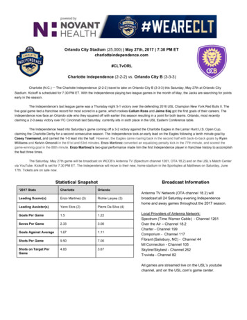
OPERATING MANUAL12-Channel ScanningThermocouple ThermometerMENU FEXIT 0CLEARModel No.92000-00 Benchtop 115V92000-05 Benchtop 230VEach of the up to 12 thermocouples is scanned once every four seconds to once everyhour (settable). The current readings are displayed on the large liquid crystal display. Readings that exceed a maximum or minimum value can be set to trigger an alarm.Thermocouples of types: B, E, J, K, N, R, S or T can be used.Up to 4,680 data points can be logged (stored) within the unit, including readings from all12 channels and the date and time of the readings.The unit can be directly connected to a printer to provide a continuous printout, and/or toyour computer. Software to permit a personal computer using WINDOWS to store datafrom the unit, remotely operate the unit, and synchronize the operation of multiple unitsis included.Cole-Parmer Instrument Co.625 East Bunker CourtVernon Hills, Illinois U.S.A. 60061-1844(847) 549-7600(847) 247-2929 (fax)800-323-4340www.coleparmer.come-mail: techinfo@coleparmer.comA-1299-0763Edition 04 ColeParmerCP cover110/12/01, 10:59 AM
EU Declaration of ConformityName of Apparatus: Scanning Thermocouple ThermometerModel Number: 92000-05Description of Apparatus: 12-Channel Benchtop ThermocoupleScannerBarnant Company declares that the above model is in conformityto the following harmonized standards and tionsManufacturer’sReport Number73/23/EEC93/68/EECEN61010-1/A2: : 1998TR9867The last two digits of the year in which the current configuration ofthe the above model was assessed per the Low Voltage Directiveis: 00.Manufacturer:Barnant Company DivisionCole-Parmer Instrument Company28W092 Commercial AvenueBarrington, IL 60010-2392USATel.: 847-381-7050Manufacturer’s Signature:10 November, 2000James W. DollVice President, EngineeringDatePrinted in U.S.A.040101CP cover210/12/01, 10:59 AM
IntroductionSafety PrecautionsIntroductionThis Scanning Thermocouple Thermometer continuously monitorstemperatures at up to 12 locations. It is designed for laboratory orindustrial applications for unattended temperature monitoring. An alarm isset off when any thermometer exceeds its preset minimum or maximumtemperature. Temperature data is stored within the unit and can beoutput to a printer or PC.Safety PrecautionsDANGER:If thermocouples are at a high voltage, this voltage may bepresent at other points inside the instrument and outside atall the connectors.WARNING: Disconnect or turn off power source before makingconnections.WARNING: Turn power off and completely disconnect instrument.Disconnect power source, thermocouples, computer, links,and printer.WARNING: Other than a lithium battery, there are no user serviceableparts inside. Replacement of the lithium battery must beperformed per the Maintenance section of this OperatingManual. Refer servicing to your dealer.CAUTION: Be sure available power matches instrument power requirements.CAUTION: Protection provided by the unit may be impaired if the unit isinstalled and/or operated in a manner inconsistent withthese instructions.WINDOWS, WINDOWS NT - Reg TM Microsoft Corp.CENTRONICS - Reg TM Genicom CorporationTrademarks bearing the symbol in this publication areregistered in the U.S.A. and in other countries.1BA 1-12110/12/01, 11:01 AM
Table of ContentsPageIntroduction .Safety Precautions .Table of Contents .Features .Package contents .Quick reference:Front panel controls .Front panel display .Rear panel connections .Rear panel connectionsThermocouple connections .Power switch .10-28V DC jack .PC/IN jack .OUT/LINK jack .PARALLEL PRINTER connection .TRIGGER GND connection .Installation .Front panel displays and controls1 STORE button .2 LOG button .3 RECALL button .4 PRINT button .5 MAX button .6 MIN button .7 AVG button .8 HOLD button .9 SCAN button .0 CLEAR button .MENU button .Up-Down Arrow keys .Left-Right Arrow keys .EXIT button .ALARM button .Temperature alarms .Other alarms .MENUAbout the MENU .2BA 1-12210/12/01, 11:01 2323232526
Table of Contents continuedPageMENU - How to:Set the Scale .Change the resolution .Enable/Disable channels .Setup thermocouple types .Adjust the display contrast .Set trigger type .Set trigger mode .Adjust the scan rate .Adjust the print rate .Adjust the log rate .Set the alarm mode .Set the alarm print .Set HI alarm(s) .Set LO alarm(s) .Set alarm hysteresis .Adjust HI alarm setpoints .Adjust LO alarm setpoints .Enable/Disable the alarm beeper .Set the date format .Set the date .Set the time .Do a field calibration .Print a calibration report .Calibration to water .Power up modes .MaintenanceCare and cleaning .Battery .Warranty .Product Return .Technical Assistance .Specifications .AppendicesA Error messages .B Guidelines to Thermocouple Selection .C Temperature conversion .D Menu flow chart .E Factory default settings 657585959596062636364663BA 1-12310/12/01, 11:01 AM
FeaturesInput Up to 12 thermocouple probes, each connected to a separate channel. Thermocouples can be different types. Thermocouples of types B, E, J, K, N, R, S or T can be used. Channels can be individually enabled or disabled.Data storage Up to 4,680 data records can be stored in the unit (a record includesreadings of all 12 channels plus time and date). Data can be logged (automatically stored). Current data can be manually stored by pushing the STORE button. Data is maintained even when the instrument is turned off or unplugged from power.Display Displays the thermocouple number and temperature as scanned. Operator can set the scan interval from a minimum of 4 seconds to amaximum of 1 hour. Readings can be stored and displayed in C, F, K, or R. Resolution to 0.1 can be displayed. Display can show: current, maximum, minimum, or average temperature. Average temperature display also displays the number of readingsbeing averaged. Hold function freezes all 12 channels.Data output All 12 channels can be output to a printer simultaneously. Current, stored, or logged data can be directly sent to a printer(CENTRONICS parallel). Time between printing cycles is adjustable. Current, stored, or logged data can be sent to a personal computer(PC)(RS-232 serial).Calibration Channels can be individually calibrated manually. Factory calibration remains in memory and can be restored at any time.Software Software (for a PC running WINDOWS 95/98 or WINDOWS NT) isincluded. Software use is optional. Software installation instructions and software manual are on theprovided CD-ROM. See readme.txt for latest information. Software permits control of up to 8 units. Real time data collection. Data can be input to spreadsheet or graphing software.4BA 1-12410/12/01, 11:01 AM
Features continuedPackage contentsAlarms High and low alarm temperatures can be set for each channelindividually. An open thermocouple automatically triggers an alarm. An alarm causes the alarm icon to be displayed, and emits an audiblebeep. The audible beep can be disabled.Error messages Messages indicate channel and fault condition.Package contentsMENUScanning thermometerIncludes wire stand for desktopconvenience. FEXIT 0CLEARLink cableRJ-11 to RJ-11 seven feet long. Use tointerconnect scanning thermometer instruments.PC adapterRJ-11 to DE-9 female. Used to connectinstrument to your PC, using the link cable.Trigger ConnectorOperating ManualThis book.Warranty cardAC Adapter - as supplied.SoftwareWINDOWS 95/98 and WINDOWS NT on CD-ROM. Serial software specifications on CD-ROM.Not suppliedPrinter cableDB25 male to the input connection of your parallel printer.5BA 1-12510/12/01, 11:01 AM
Quick ReferenceFront Panel ControlsSee the page number (in parenthesis) for full information about the item.Use Left-Right arrow keys to select a channel for display. Scanningstops. Push SCAN to resume. (22)Use Up-Down arrow keys to scroll thru the MENU. Otherwise inactive. (21)MENU Push to sequence through menu choices for instrument setup. (21)MENU FEXIT Push to exit any menu or display mode. Operation continues. (23)EXIT ALARM Push to silence the audible alarm. Alarm icon remains. (23)0CLEARCLEAR Push CLEAR then push STORE, LOG, MAX, MIN, AVG or ALARM.Clears respective value(s) from memory. (20)SCAN Push to resume scanning display after pushing Left-Right arrowkeys. Also, this immediately initiates a new scan. (20)LOG Push totoggle datalogging. (14)STORE Push tostore the current setof readings inmemory. “STORE”appears in thedisplay. (13)6HOLD Push to freeze current display readings. Scanning continues.Left-Right arrow keys select channel displayed. To exit push HOLD. (19)PRINT Push toturn printing onor off. (16)RECALL Push to scrollthrough logged readings.Up-Down arrow keys scrollthrough reading numbers.Left-Right arrow keysselect channel displayed.RECALL cycles throughreading date, reading time,and reading temperature.Push and release EXIT toexit. (15)MAX Push to display themaximum reading and timesince last power up or lastcleared. Left-Right arrowkeys select channel displayed. To reset pushCLEAR then MAX. To exitpush EXIT. (17)AVG Push to display the average reading and number of readings sincelast power up or last cleared. Left-Right arrow keys select channel displayed. To reset push CLEAR then AVG. To exit push EXIT. (19)MIN Push to display the minimum reading and reading time since lastpower up or last cleared. Left-Right arrow keys select channel displayed. Toreset push CLEAR then MIN. To exit push EXIT. (18)7
Quick Reference ContinuedFront Panel DisplayRear Panel Connections123 F24ALARMSTORE54678Note: Example display1. CH and the channel numberdisplay the thermocouple that isbeing read.2. The number of the channel beingdisplayed is repeated here.3. The temperature is displayed.4. The temperature scale is given.5. A flashing channel numbershows a problem with that probe.6. Words across the bottom of thedisplay indicate status of theinstrument. (Example: STOREindicates that temperaturerecords are logged or stored.)7. The word ALARM flashes whenan alarm is present.8. When flashing, indicates analarm.1.MODEL ####-##Mfg. By Barnant CompanyBarrington, IL 60010-2392USA12 CHANNEL TERMOCOUPLE SCANNER127839PC/IN456101112OUT/LINKTRIGGER GNDPARALLEL PRINTER10-28 VDC7-20 VAC500 MA2. 3.1. 1-122.3. 10-28V DC4. PC/IN5. OUT/LINK6. PARALLELPRINTER7. TRIGGER GND4.RS2325.6.7.Connect thermocouples here (two blade mini-ANSIconnectors).Power switch: on, off.Power supply input. Connect the input connector of thesupplied AC adapter here.Connect (using supplied cable) to a serial port on your PCcomputer (RS-232 connection).For linking additional 12-Channel Scanning ThermocoupleThermometer instruments. Connect OUT/LINK on oneinstrument to PC/IN, using RJ-11 connectors.Use a standard parallel printer cable (25 pin D-subconnector) to directly connect a PC printer.Connect for external events to trigger printing ordata storage.8BA 1-12810/12/01, 11:01 AM
Rear Panel ConnectionsThermocouple connectionsPower switchAMODEL ####-##Mfg. By Barnant CompanyBarrington, IL 60010-2392USA12 CHANNEL TERMOCOUPLE SCANNER127834910PC/IN561112OUT/LINKPARALLEL PRINTER10-28 VDC7-20 VAC500 MATRIGGER GNDRS232B123456789101112A. Thermocouple connections Connect up to twelve thermocouples here. Jacks are for two blade mini-ANSI connectors. Thermocouples of types B, E, J, K, N, R, S, or T can be used. SeeAppendix B for a description of thermocouple types. Any combination of thermocouple types can be used at the same time. If a thermocouple connection (channel) is not used it may be disabledusing the Menu. See Menu - How to: Enable/Disable channels onpage 30.B. Power switchToggle to l to turn power to the instrument on.Toggle to 0 to turn power to the instrument off.When power is turned on the display goes through a display checksequence: all display elements are turned on momentarily, thenthe 1,2,.12 icons (small numbers) turn off in sequence, and then thedisplay switches to normal operation.An internal lithium battery maintains the real-time clock for power outages for over a year.9BA 1-12910/12/01, 11:01 AM
Rear Panel Connections continued10-28V DC jackABPC/IN jackMODEL ####-##Mfg. By Barnant CompanyBarrington, IL 60010-2392USA12 CHANNEL TERMOCOUPLE SCANNER123456789101112PC/INOUT/LINKPARALLEL PRINTERTRIGGER GNDRS23210-28 VDC7-20 VAC500 MA10-28 VDC7-20 VAC500 MAA. 10-28V DC jack (Power supply input)Connect the input connector of the supplied AC adapter here.Polarity may be either center , or center –, or AC.The instrument will accept: 10-28V DC (non-polarized) input @ 300 mA,or 9-20V AC, 50-400 Hz @ 500 mA.The input connector is a 2.5 mm ID, 6.4 mm OD power jack. (Switchcraft760 or 765 or equivalent.)PC/INB. PC/IN jack (Computer or link connection)Computer connection Connect (using supplied cable) to aserial port on your PC computer (RJ-11 connector to DE-9female using the RS-232 protocol). Software commandsand instructions are available on the supplied CD-ROM. Seepackage contents page 5.Link connection Connect PC/IN (using wire with RJ-11 connectors) toOUT/LINK connection on additional instruments. Uses Linkable Instrument Network connectors and software protocol.10BA 1-121010/12/01, 11:01 AM
Rear Panel Connections continuedOut/Link jackParallel Printer connectionTrigger Gnd connectionMODEL ####-##Mfg. By Barnant CompanyBarrington, IL 60010-2392USA12 CHANNEL TERMOCOUPLE SCANNER123456789101112PC/INOUT/LINKPARALLEL PRINTER10-28 VDC7-20 VAC500 MATRIGGER GNDRS232ABCA. OUT/LINK jackLink connection. Connect OUT/LINK (using wire withRJ-11 connectors) to PC/IN connection on additionalinstruments. Uses Linkable Instrument Networkconnectors and software protocol. Either end of thechain can be used as the computer connection.OUT/LINKRS232PARALLEL PRINTERB. Parallel Printer connectionUse a standard parallel printer cable (DB-25male to 36 position CENTRONICS male) todirectly connect a PC printer. See PRINT button on page 16. No additional software or hardware is required for printing.C. TRIGGER GND connectionOptional. Connect for external events to triggerprinting or data storage. Contact closure or opencollector type logic signal to ground. (Internal 5VDC pull-up through 5K ohms resistance with100pf capacitance to ground.) Mating connectorsupplied.TRIGGER GNDTRIGGER GND1 2345Use pins 1 & 2 for contact closure.Pins 3-5 not used.11BA 1-121110/12/01, 11:01 AM
Installation1MODEL ####-##Mfg. By Barnant CompanyBarrington, IL 60010-2392USA12 CHANNEL TERMOCOUPLE SCANNER127839PC/IN456101112OUT/LINKPARALLEL PRINTER82TRIGGER GNDRS23210-28 VDC7-20 VAC500 MA5641. Attach up to 12 thermocouples.7232. Connect the AC adapter to the instrument.3. Plug the AC adapter into an outlet.4 - 7 are Optional4. Connect the PARALLEL PRINTER output to a PC printer (standardparallel port cable - not supplied).5. Connect the PC/IN jack to a serial port of your WINDOWS PC (usethe supplied cable).6. To interconnect instruments connect the OUT/LINK jack of oneScanning Thermocouple Thermometer to the PC/IN jack of the next(cable supplied).7. To control printing or data storage by external events, connectmomentary contact events to the TRIGGER GND connector.8. Switch power switch to on.12BA 1-121210/12/01, 11:01 AM
Front panel displays and controls1 STORE buttonMENU. FEXIT D9SCAN0CLEAR11 STORE buttonPush to store one record cycle of the current set of readings in memory.(Same as LOG, except only one record is stored.)When a numerical entry is required and the NUM icon is on, push toenter a ‘1’.ab FSTOREThe word “STORE” a and the record number being stored b appear inthe display for about 3 seconds. Then the display returns to normal.c F4STORE“STORE” c appears, and remains in the display when one or more recordcycles are in storage (STORE and/or LOG).Use to save a particular data record. A record includes readings from all 12 channels plus the time anddate. Up to 4,680 records may be stored. Memory is shared with LOG.When no more data can be stored the display reads “STOREFULL”. To clear (erase) stored records, push CLEAR, then push STORE.“STORE” disappears from the display.13BA 13-251310/12/01, 11:03 AM
Front panel displays and controls continued2 LOG buttonMENU. FEXIT 0CLEAR22LOG2 LOG buttonPush to log record cycles as they are read. (Same as STORE, onlycontinues automatically.)When a numerical entry is required and the NUM icon is on, push toenter a ‘2’.Push again to turn logging off. F4LOGaThe word “LOG” a appears and remains in the display while records arebeing logged.“STORE” appears, and remains, in the display when one or more recordsare in storage.Use to save a particular set of data records. Readings from all 12 channels are logged. How often records are logged is set using the MENU - LOGprocedure, page 37, which may be different from the scan rate. The time and date of the reading is logged. Up to 4,680 records may be logged. Memory is shared with theSTORE function. When no more data can be stored the displayreads “LOG FULL”. To clear (erase) stored records, push CLEAR, then push LOG.“STORE” will disappear from the display.14BA 13-251410/12/01, 11:03 AM
Front panel displays and controls continued3 RECALL buttonMENU. FEXIT 0CLEAR33RECALL3 RECALL buttonPush to recall stored (STORE or LOG) data.When a numerical entry is required and the NUM icon is on, push toenter a ‘3’. “RECALL” appears and remains in the display during recall. The LOG or STORE record number and time of channel 1 aredisplayed first.1STORE RECALLPush RECALL again to display the temperature. F1STORE RECALLPush RECALL again to display the date.1STORE RECALL(continued on next page)BA 13-25151510/12/01, 11:03 AM
Front panel displays and controls continued3 RECALL button continued4 PRINT buttonMENU. FEXIT N0CLEAR43 RECALL button continued Any time during RECALL push the Up-Down arrow keys to scrollthrough the stored records. Any time during RECALL push the Left-Right arrow keys to scrollthrough the channels. To exit RECALL push EXIT.4PRINT4 PRINT buttonPush to print on the printer attached to the PRINTER port. Push again tostop printing.When a numerical entry is required and the NUM icon is on, push toenter a ‘4’. “PRINT” appears and remains in the display. Records are printed at intervals set in the MENU.See MENU - How to adjust the print rate, see page 36. Push PRINT again to turn off printing.Example CHCHCH4:8:12:16BA 13-251610/12/01, 11:03 AM74.674.573.7
Front panel displays and controls continued5 MAX buttonMENU. FEXIT 0CLEAR55MAX5 MAX buttonPush to display the maximum temperature logged for each channel. Thedisplay continues to scan channels.When a numerical entry is required and the NUM icon is on, push toenter a ‘5’. F2MAX “MAX” appears and remains in the display.The time and maximum reading for a channel are displayed (sincepower up or last cleared).Push MAX again to switch between the time and the date.Use Left-Right arrow keys to stop scanning and to choose thechannel whose maximum value is displayed. Push SCAN to returnto scanning channels while remaining in MAX.Push MIN to switch the display to the minimum logged value of thedisplayed channel.Push EXIT to exit.17BA 13-251710/12/01, 11:03 AM
Front panel displays and controls continued6 MIN buttonMENU. FEXIT 0CLEAR66MIN6 MIN buttonPush to display the minimum temperature logged for each channel. Thedisplay continues to scan channels.When a numerical entry is required and the NUM icon is on, push toenter a ‘6’. F2MIN “MIN” appears and remains in the display.The time and minimum reading for a channel are displayed (sincepower up or last cleared).Push MIN again to switch between the time and the date.Use Left-Right arrow keys to stop scanning and to choose thechannel whose minimum value is displayed. Push and releaseSCAN to return to scanning channels while remaining in MIN.Push MAX to switch the display to the maximum logged value ofthe displayed channel.Push EXIT to exit.18BA 13-251810/12/01, 11:03 AM
Front panel displays and controls continued7 AVG button8 HOLD buttonMENU. FEXIT 9SCAN0CLEAR87 AVG buttonPush to display the average temperature for each channel and thenumber of readings that are being averaged. The display continues toscan channels.When a numerical entry is required and the NUM icon is on, push toenter a ‘7’. F5AVG “AVG” appears and remains in the display.Readings from when the instrument was last powered up orcleared are averaged.Opened channel readings are not averaged.Use Left-Right arrow keys to stop scanning and to choose thechannel whose average is displayed. Push SCAN to return toscanning channels while remaining in AVG.Push AVG again to exit.8HOLD8 HOLD buttonPush to hold the current record in display.When a numerical entry is required, and the NUM icon is on, push toenter an ‘8’. “HOLD” appears and remains in the display. Channel scanning, logging, printing continue normally but thedisplay remains. Push HOLD or EXIT to exit.19BA 13-251910/12/01, 11:03 AM
Front panel displays and controls continued9 SCAN button0 CLEAR buttonMENU. FEXIT 9SCAN0CLEAR909 SCAN buttonPush to start a channel scan.When a numerical entry is required and the NUM icon is on, push toenter a ‘9’. Each channel is displayed for three seconds. Use to return to scanning after scanning is stopped by using theLeft-Right arrow keys. Causes an immediate scan.0CLEAR0 CLEAR buttonPush CLEAR, then push AVG, ALARM, MAX, MIN, STORE or LOG toclear that value.When a numerical entry is required and the NUM icon is on, push toenter a ‘0’. CLEAR - AVG erases the 12-Channel record containing theaverage temperature from memory. CLEAR - ALARM turns the alarm buzzer off, all alarm conditions,error messages, and temperature out of range alarms. Normallypush ALARM when an alarm occurs, that stops the alarm buzzerand checks the alarm condition. CLEAR - MAX erases the 12-Channel record containing themaximum temperature from memory. CLEAR - MIN erases the 12-Channel record containing the minimum temperature from memory. CLEAR - STORE erases the 12-Channel records that have beenlogged or stored in memory ( CLEAR - LOG). CLEAR - LOG erases the 12-Channel records that have beenlogged or stored in memory ( CLEAR - STORE).20BA 13-252010/12/01, 11:03 AM
Front panel displays and controls continuedMENU buttonUp-Down Arrow keysMENU. FEXIT 0CLEARMENUUp-Down Arrow KeysMENUMENU buttonPush to scroll through the menu to enter or change setup parameters.The word “SCALE” appears in the display and the current scale setting(for example F) flashes.To scroll backwards through the menu choices push and hold MENUthen press the Left arrow key.See MENU, starting on page 26, for a complete selection of MENUchoices and how to set up parameters.Up-Down Arrow keysActive within the MENU. Used to scroll through menu options.21BA 13-252110/12/01, 11:03 AM
Front panel displays and controls continuedLeft-Right Arrow keysMENU. FEXIT 0CLEARLeft-Right Arrow KeysLeft-Right Arrow keysActive within the MENU. Used to scroll through menu options. Manually select a channel.22BA 13-252210/12/01, 11:03 AM
Front panel displays and controls continuedEXIT buttonALARM buttonMENU. FEXIT 9SCAN0CLEAREXITEXITEXIT buttonDuring MENU, push to EXIT the MENU and save any menu choices thathave been made. SAVING SETUP is displayed for two seconds, then theinstrument returns to scanning.During STORE, RECALL, MAX, MIN, AVG, CLEAR or HOLD displays,push to EXIT the display and return to scanning. ALARMALARM buttonPush to turn off the alarm beeper. The flashing alarm icon and otheralarm displays remain.When a numerical function is required and the NUM icon is on, push totoggle between and -. F24STOREALARM12Temperature AlarmsWhen an alarm occurs the alarm beeper will beep (if ALARM BEEPER isset to ON in the menu) the printer will print the alarm record (if ALARMPRINT ON is set in the menu), the alarmed channel 1 and the alarm icon2 will flash.(continued on next page)23BA 13-252310/12/01, 11:03 AM
Front panel displays and controls continuedALARM button continued F24STOREALARM3Temperature Alarms continued HI temperature alarm: When a thermocouple detects a temperature above the HI limit setting in the menu, ALARM is displayed,the alarm icon and the channel number 3 flash. HI will flash whenthat channel is displayed. LO temperature alarm: When a thermocouple detects atemperature below the LO limit setting in the menu, ALARM isdisplayed, the alarm
Thermocouple Thermometer Each of the up to 12 thermocouples is scanned once every four seconds to once every hour (settable). The current readings are displayed on the large liquid crystal display. . Barnant Company Division Cole-Parmer Instrument Company 28W092 Commercial Avenue Barrington, IL 60010-2392 USA Tel.: 847-381-7050 Manufacturer .