Transcription
North SeaMeasurement Workshop1998 PAPER 22"( . ;.,THE REVISION OF ISO 5167 - AN UPDATEM Reader-Harris, National Engineering Laboratory
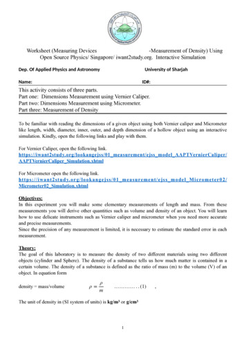
16th NORTH SEA FLOW MEASUREMENT WORKSHOP 1998THE REVISION OF ISO 5167 AN UPDATEDr Michael Reader·Harris, National Engineering1LaboratoryINTRODUCTIONISO TC30/SC2 WG11, of which I am Convener, is responsible for producing a draft of ISO5167 which takes into account the work on differential pressure fiowmeters which has beendone in recent years and will provide a thorough revision of ISO 5167-1 [1}. WG11 wasestablished in 1996 and a Committee Draft was issued to SC2 for discussion at ISOTC30/SC2 "in June 1998. "A" revised Committee- Drafrincorporating ·comments-shoutd beissued at the end of this year with the expectation that a "revised International Standard willbe published in 2001. This paper brings the North Sea Workshop up to date on the current situation with regard tothe revision of the standard. It describes the planned changes and gives at least anindication of the research on which the changes are based.ISO 5167 will be divided into 4 parts: general (ISO 5167-1), orifice plates (ISO 5167-2),nozzles and Venturi nozzles (ISO 5167-3), and Venturi tubes (ISO 5167-4). Many users willonly require the general part and one other part. The most significant areas of change fromthe existing ISO 5167-1 are given below. It is likely that further changes will take place in thenext three years." "2 ORIFICEPLATE INSTALLATION EFFECTSAND FLOW CONDITIONERSA very large amount of data on installation effects on orifice plates has been collected inrecent years, particularly in the USA and in Canada but also in the UK and in Germany. Thedata and the methods of analysis are given in [2]. Revised straight lengths based on ananalysis of these data, initially undertaken by API but in which representatives of countriesoutside North America are now involved, will be included. The data downstream of twobends were taken with various distances between the two bends, and the required distancesbetween pairs of bends will be included in the table. The table of required upstream straightlengths lncluded in the Committee Draft of ISO 5167-2 discussed at SC2 in June 1998 isgiven here as Table 1. Only thermowells smaller than 0.030 will be permitted upstream ofthe orifice. Some pairs of bends in perpendicular planes with small separation gave verylarge shifts in discharge coefficients, although other pairs of bends with the same separationgave much smaller shifts. It will be recommended that if there is a possibility of a fittingcreating severe swiri, as two bends in perpendicular planes with separation less than 50 or aheader may do, a flow conditioner should be used.In ISO 5167-1 a compliance test for flow conditioners will be included: using a primary deviceof diameter ratio 0.67 the shift in discharge coefficient from that obtained in a long straightpipe must be less than 0.23 per cent when a flow conditioner is used in each of foursituations: a)in good flow conditions,b)downstream of two bends in perpendicular planes (ratio of bend radius to pipediameter approximately equal to 1.5; separation between curved portions of bendsless than two pipe diameters)c)downstream of a half closed gate valve (or D-shaped Orifice)d)in conditions of high swirl downstream of a device producing a high swirl (the deviceshould produce a maximum swirl angle across the pipe of 25 - 30 180 downstreamof it or 20 - 25 300 downstream of it).001
Table 1- Required straight lengths between orifice plates and fittings without flow conditionersValues expressed as multiples of internal diameter DUpstream (inlet) side ofthe orifice plateDiameterratioSingle 90 bendpTwo 90 bends insame plane(S 30D)·Two 90 bends inthe sameplane:S-configuration(lOD S).Two 90 bends inperpendicular planes(8) 444300,674435440,75.) S is the separation between.B10Two 90 bends inthe sameplane:S-configuration(30D S 1OD)·Two 90 bends inperpendicular planes(5D 8).Two 90 bends inperpendicular planes(15D 8 5D)·Single 90 tee4567A10B101016AB 305060951050951830509544 30306544 30 9530the two bends measured fromto131830B1944194419194444304430the downstreamA19Single 45 bendTwo 45 bends inthe sameplane(S 22D)·.8Reducer2DtoDover alength of1,5Dt03DExpanderO,5DtoDover alength ofDt02DFull boreball valvefully open9to11AbruptsymmetricalreductionThermometer pocketorwell"ofdiameters O,03D12Downstream (outlet)side of theorifice plateFittings(columns 2to 11) andthedens itometerpocket13BABABBABABAABA 5 5 16 8 12 6 30 15 5 9534444 30 22 II .3830end of the curved portion of the upstream bend to the upstre end of the curved portion of147B2333,53,584A4667thedownstream bend.) The installation of thermometer pockets or wells will not alter the required minimum upstream straight lengths for the other fittings . ) There are insufficient data for this configuration: the lengths for p 0,4 should be used . ) There are no data for this configuration: the lengths for P 0,4 are at least sufficient.NOTES:1. The minimum straight lengths required are the lengths between various fittings located upstream or downstream of the orifice plate and the orifice plate itself. Straight lengths shallbe measured from the downstream end of the curved portion of the nearest (or only) bend or of the tee or the downstream end of the conical portion of the reducer or expander.P 0,2 can be taken to be equal to those for P 0,2.3. Most of the bends on which the lengths in this table are based had a radius of curvature equal to 1,5D, but it may be used for bends with any radius of curvature.4. Column A for each fitting gives lengths corresponding to 'zero additional uncertainty' values (see 5.2.3).5. Column B for each fitting gives lengths corresponding to '0,5% additional uncertainty' values (see 5.2.4).2. Lengths for 2
This last installation was included to give a swirl similar to that found downstream of a headertested at NEL. As well as the test for p 0.67 the flow conditioner must pass the high-swirl test(d) for /3 0.4. This test for p 0.4 is included because, although for non-swirling flow shifts indischarge coefficient increase with /3, this is not necessarily true for swirling flow. Provided thatthe flow conditioner is geometrically similar for all pipe diameters this compliance test need onlybe passed for one diameter, and if it is passed for a range of Reo greater than 3 x 10⁶ it will betaken to have been passed for all Reo 3 x 10⁶. If a flow conditioner passes this test it may beused with no additional uncertainty downstream of any fitting with any diameter ratio up to 0.67.If it is desired to use the flow conditioner for /3 0.67 additional testing is required. Requireddistances between the primary device and flow conditioner and between upstream fittings andflow conditioner will be determined in the course of the tests since a flow conditioner will notpass for all distances. The compliance test is included in ISO 5167-1 because the same test isapplied whichever primary device is used; however passing the test with one type of primarydevice does not imply that the test would have been passed with all types of primary device. Tests were undertaken with orifice plates at 5wRI to check that there are flow conditionerswhich meet these compliance tests with reasonable overall distances between fittings andorifice plate. These showed that there is a location for a 19 tube bundle of defined geometry atwhich the compliance test is satisfied provided that the overall length between orifice plate andtube bundle is at least 30D; similarly there is at least one location at which both the Gallagherand the K-Lab Laws Nova 50 E pass this test provided that the overall length between orificeplate and either flow conditioner was at least 18D. These lengths are not minimum upstreamlength requirements using the tube bundle or the flow conditioners; they are lengths at whichsuccessful tests were carried out. Measurements of required length are taken from the orificeface to the upstream fitting itself so that the weld neck is included within the straight length; forexample the distance is measured to the downstream end of the curved portion of a bend. Theresults are presented without naming the conditioners in [2], but names are given in [3].The installation requirements given in the current draft of Part 2 of API 14.3 [4] are almostidentical to those proposed in ISO 5167. This is significant progress.3 EXPANSIBILITY EQUATION FOR ORIFICE PLATESThe orifice plate discharge coefficient equation has been revised on the basis of data collectedin the last 20 years, and it is appropriate that the same process of revision should occur for theexpansibility factor.The existing equation for the orifice expansibility factor was derived by Buckingham [5] on thebasis largely of data collected at tests in Los Angeles in 1929. Using these data Buckinghamderived the equation:&) 1-(0.41 03Sp4)IIp ,(1)Ap)where &, is the expansibility coefficient, 6.p is the differential pressure across the orifice plate, p,is the static pressure at the upstream tapping and Ie is the isentropic exponent.It is significant that in analysing the data Buckingham neglected the effect of Reynolds numberon the grounds that above a throat Reynolds number, Reg. of 2 x 10⁵ the discharge coefficient isconstant. It is now known that the discharge coefficient continues to change with Red above thisvalue. The work of Bean and Buckingham has nevertheless set a pattern for subsequentworkers in this area. As part of the EEC Orifice Project data were collected on expansibility factors. At NEL on the100 mm (4-inch) pipe run data were collected for three diameter ratios, 0.2. 0.57 and 0.75, in airwith 140 kPa P1 800 kPa. Details of the analysis of the data are given in Reference I6]3
together with references to the individual data sets from all the laboratories whose data wereused. This work followed that of Kinghorn [7]. Gaz de France collected data on the 100 mm(4-inch) pipe run for a diameter ratio of 0.66 in natural gas at ReD 1.2 x 10⁶ Gasunie did not collect data on expansibility factor directly but within the data collected by themon the 100 mm (4-inch) pipe run for the discharge coefficient database it is possible to identifysets of data taken over both a significant range of static pressure and a small range of Reynoldsnumber. These data are for diameter ratios 0.2,0.57 and 0.66. Similarly CEAT did not collectdata on expansibility factor directly but within the data collected by them on the 250 mm (10inch) pipe run for the discharge coefficient database it is possible to identify sets of data takenover both a significant range of static pressure and a small range of Reynolds number. Thesedata are for a diameter ratio of 0.2.In addition to the European work CEESI on a 50 mm (2-inch) pipe run collected data for sixdiameter ratios, 0.242, 0.363, 0.484, 0.5445, 0.6655 and 0.726 in air with 115 kPa P1 2150 kPa.In order to analyse the NEL (and similar) data a common method has been to calculateeI (C&I ) measuredCI calc(2)waterwhere (CC1)measured is taken from the gas tests and Cwater from a previous water calibration of thesame orifice plate and then to use the method of least-squares to determine the constants in(3)and then to fit the slope terms, b.The problem with this method is that there is always some bias between a gas flow laboratoryand a water flow laboratory. So a better estimate of &1 is given by &11calc,2I&1 calca1-which is equivalent to fitting (Cs1)measuntd as Cincompre .Cincompr .K)'l PI l b i f J1- a(4)(1 - b f) without assuming a value foribIeibIe In the case of the Gaz de France data the value of C obtained when &1 is as close as possible to1 had been used as the reference value (equivalent to C",. in Equation (2»; this referencevalue is a single measurement, and so in [6] all the data including the reference value werefitted and values of b/(1 - a) calculated. The data from CEESI had already been analysed in asimilar manner to that used here and so in most cases a was calculated to be O.For the data from Gasunie and CEAT the Reynolds number was not constant and so it wasnecessary to apply corrections to the measured values of C&1 so that all the values areeffectively taken at one Reynolds number. To do this the dependence of C on Reynoldsnumber given in the Reader-Harris/Gallagher Equation [8] was assumed.For each set of data calculations were performed for two functions, f:j t J .K) IlPIand4!lp"PI(5)
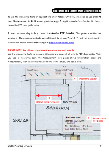
(6)where P2 is the static pressure at the downstream pressure tapping.The first equation issimpler but the latter is based on the best physical understanding.It was clear that where thereis a wide range of values of P P1' that is in the NEL, Gaz de France and CEESI data, usingEquation (6) gives a smaller standard deviation of the data about the obtained fit, and soEquation (6) is used to reduce bias in the final equation. More complex forms of equation thanEquations (5) and (6) were tried but only gave marginal improvements in quality of fit. Thevalues of b" (for use with f in Equation (6» are dependent on p and are shown in Figure 1. For p:S 0.66 there is a linear dependence on p. At higher diameter ratios the measured values lieabove a fitted line and so, to avoid bias at small P due to the points for large p, b" has been fittedas follows:(7) Fig. 1 Experimental data: coefficients of f In Equation (4) (f 8S In Equation UNlEGAZ DE FRANCEx CEESIo CEAT.ISO 5167-1: 1991- - - FITTED LINE-SEEEQUATION(8)o60.3 -1o--- ent functions of P did not give a worthwhilefollowing equation was obtained:improvement0.350.3in fit. On fitting the data the (:.)
ISO 5167 will be divided into 4 parts: general (ISO 5167-1), orifice plates (ISO 5167-2), nozzles and Venturi nozzles (ISO 5167-3), and Venturi tubes (ISO 5167-4). Many users will only require the general part and one other part. The most significant areas of change from the existing ISO 5167-1 are given below. It is likely that further changes will take place in the next three years." "2 .