Transcription
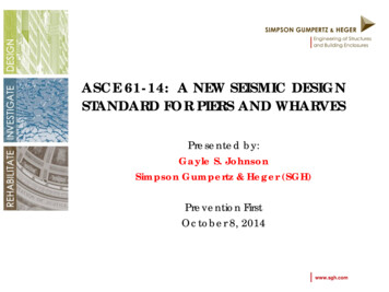
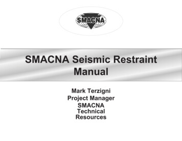
CONCEPTS OF SEISMIC-RESISTANT DESIGNInstructional Material Complementing FEMA 451, Design ExamplesDesign Concepts 7 - 1This topic introduces the concepts of seismic-resistant design from aphilosophical perspective. For this reason, the NEHRP RecommendedProvisions, the International Building Code, and various standards arereferenced directly.The slide shown is a ductile concrete moment resisting frame structure(parking garage) that collapsed during the Northridge earthquake. Note thatthere is tremendous deformation capacity in the columns of the perimetermoment frame. The collapse was actually due to the loss of several interior“nonstructural” gravity columns that were not sufficiently detailed toaccommodate the large inelastic displacement demands imposed by theearthquake. More is said about this in a later slide so do not over emphasizehere. The point is that many “secondary” items are, in fact, of primaryimportance.FEMA 451B Topic 7 NotesEarthquake Engineering 7 - 1
Steps in the Seismic Design of a Building1.2.3.4.5.6.7.8.9.Develop concept (design philosophy)Select structural systemEstablish performance objectivesEstimate external seismic forcesEstimate internal seismic forces (linear analysis)Proportion componentsEvaluate performance (linear or nonlinear analysis)Final detailingQuality assuranceInstructional Material Complementing FEMA 451, Design ExamplesDesign Concepts 7 - 2In this topic, only the first three bullet items are addresses. More is saidabout the other points when the NEHRP Recommended Provisions arediscussed.The points are supposed to be something of a chronological list of designconsiderations. However, performance objectives could be listed as eitherPoint 2 or 3 because the structural system and the performance objective gohand-in-hand.FEMA 451B Topic 7 NotesEarthquake Engineering 7 - 2
Seismic Design Practice in the United States Seismic requirements provide minimum standards foruse in building design to maintain public safety in anextreme earthquake. Seismic requirements safeguard against major failuresand loss of life – they DO NOT necessarily limitdamage, maintain function, or provide for easy repair. Design forces are based on the assumption that asignificant amount of inelastic behavior will take placein the structure during a design earthquake.Instructional Material Complementing FEMA 451, Design ExamplesDesign Concepts 7 - 3The points from the next three slides come from the Commentary to the2003 NEHRP Recommended Provisions; hence, they are elated to newbuildings.These points emphasize that life safety is the primary design objective.Even though the Provisions is implicitly designed to control damage fromfrequent low intensity earthquakes, there is no objective criteria to guaranteesuch performance.After the 1994 Northridge earthquake, damage to many buildings designedunder “modern” provisions exhibited significant damage. This led to a rethinking of the seismic provisions in the United States and to the movetowards performance-based design.FEMA 451B Topic 7 NotesEarthquake Engineering 7 - 3
Seismic Design Practice in the United Statescontinued For reasons of economy and affordability, the designforces are much lower than those that would berequired if the structure were to remain elastic.In contrast, wind-resistant structures are designed toremain elastic under factored forces.Specified code requirements are intended to provide forthe necessary inelastic seismic behavior.In nearly all buildings designed today, survival in largeearthquakes depends directly on the ability of theirframing systems to dissipate energy hysteretically whileundergoing (relatively) large inelastic deformations.Instructional Material Complementing FEMA 451, Design ExamplesDesign Concepts 7 - 4These two points are the key to seismic-resistant design. If possible, itwould certainly be desirable to design structures to remain elastic duringextreme events. However, elastic seismic forces can be several times thewind force and design for such forces is simply not economically feasible.By allowing yielding at some fraction of the elastic seismic demand, thedesign forces are reduced and the desired economy is achieved. However,for the design to be viable, the system must be detailed to accommodate theinelastic deformations that will occur after yielding.FEMA 451B Topic 7 NotesEarthquake Engineering 7 - 4
The Difference Between Wind-Resistant Designand Earthquake-Resistant DesignFor Wind:Excitation is an applied pressure or force on the facade.Loading is dynamic but response is nearly static for most structures.Structure deforms due to applied force.Deformations are monotonic (unidirectional).Structure is designed to respond elastically under factored loads.The controlling life safety limit state is strength.Enough strength is provided to resist forces elastically.Instructional Material Complementing FEMA 451, Design ExamplesDesign Concepts 7 - 5Designs to resist wind forces and seismic forces are similar only in the factthat load effects are represented by horizontal forces acting at the storylevels. In fact, part of the “appeal” of the equivalent lateral force (ELF)method is that the application of external loads and the computation ofmember forces for design is the same as it is for wind.For most buildings, dynamic wind response may be neglected. However, forvery flexible buildings and for buildings of unusual shape, aeroelasticinteraction between the wind load and structural response is possible,leading to a true dynamic response in the structure.A key point to make is that under wind, the response is assumed to beelastic. In fact, significant inelastic response would be impossible becausesystem stability would be impaired, and overall collapse could result.FEMA 451B Topic 7 NotesEarthquake Engineering 7 - 5
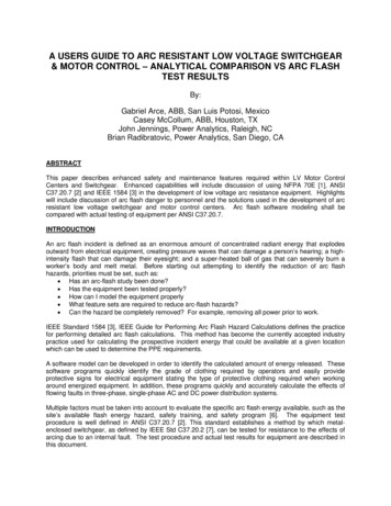
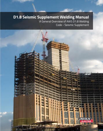
PressureBehavior Under Wind ExcitationFTimeδFFactored 50 yr windUnfactored 50 yr wind10 yr windFirst significantyieldδInstructional Material Complementing FEMA 451, Design ExamplesDesign Concepts 7 - 6Wind load is actually a pressure applied to the façade of the building. Anassumed pressure variation is shown. Note that the pressure has a nonzero static component and a time-varying (gust response) component.The static pressure component is proportional to the velocity of the windsquared, and the velocity increases along the height. Both windward andleeward pressures exist and are typically integrated over the surface area toproduce story forces. Although the story forces will eventually be transferredto floor diaphragms, the forces do not originate in the diaphragms (seismiccontrast to be presented later).Note that the force-displacement plot shows three points -- 10 year wind, 50year wind, and factored 50 year wind. The 10 year wind is used forserviceability issues (drift) and the factored 50 year wind is used for design(assuming strength based design). Under the factored 50 year wind, thestructure is still responding in a linear elastic fashion. (By linear, we meanno yielding of steel or crushing of concrete. Cracking of concrete will occurunder the factored 50 year wind (and perhaps the 10 year wind).FEMA 451B Topic 7 NotesEarthquake Engineering 7 - 6
The Difference Between Wind-Resistant Designand Earthquake-Resistant DesignFor Earthquake:Excitation is an applied displacement at the base.Loading and response are truly dynamic.Structural system deforms as a result of inertial forces.Deformations are fully reversed.Structure is designed to respond inelastically under factored loads.Controlling life safety limit state is deformability.Enough strength is provided to ensure that inelastic deformationdemands do not exceed deformation capacity.Instructional Material Complementing FEMA 451, Design ExamplesDesign Concepts 7 - 7Now the seismic contrast is presented.Emphasize that the load effect is actually a displacement (acceleration)applied to the ground. Forces develop in the structure because of the inertialresistance to the ground motion. The response is truly dynamic.The deformations are reversed -- there will be as much positivedisplacement as there will be negative displacement during the same event.For extreme events, the response will be inelastic. If fact, in areas of highseismicity, inelastic response can even be expected for the moderateearthquakes that occur every 10 years or so.Although design forces are developed in the members, the true limit state isdeformability. If fact, it does not matter how strong the structure is as longas it can be demonstrated that the strength can be sustained over severalcycles of inelastic deformation.FEMA 451B Topic 7 NotesEarthquake Engineering 7 - 7
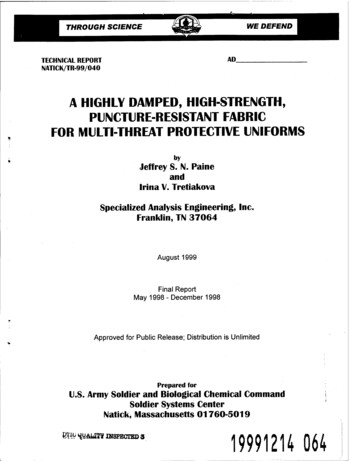
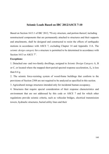
Ground Disp.Behavior Under Seismic Excitation(Elastic Response)TimeFactored seismicelastic strengthdemandFδFactored windδδGFIn general, it is not economicallyfeasible to design structures torespond elastically to earthquakeground motions.Instructional Material Complementing FEMA 451, Design ExamplesDesign Concepts 7 - 8The first cycle of seismic loading. Note that the time-history plot showsground displacement. In the frame shown, the ground is moving to the leftand the structure is lagging behind. Inertial forces develop due to the groundmotion and the dynamic response of the structure relative to the ground.For the purposes of detailing the elements, only the deformation relative tothe ground is important.The X-Y plot shows what the elastic response would be if the structure didnot yield and, for comparison, it shows the design strength under wind.FEMA 451B Topic 7 NotesEarthquake Engineering 7 - 8
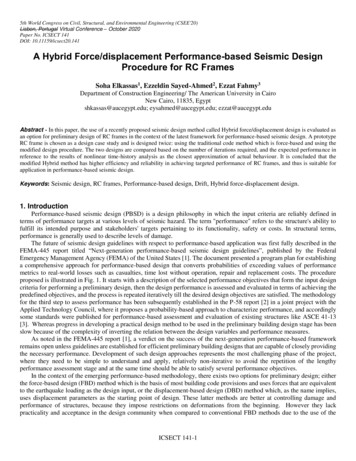
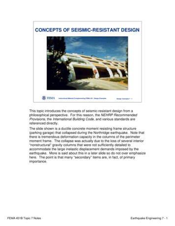
Ground Disp.Behavior Under Seismic Excitation(Inelastic Response)FTimeδLoadingδδGFInstructional Material Complementing FEMA 451, Design ExamplesDesign Concepts 7 - 9The structure has now been loaded well beyond yield. This is the loadbeyond significant yield as all previous cycles have been elastic. Inelasticdeformations have not yet reversed.FEMA 451B Topic 7 NotesEarthquake Engineering 7 - 9
Ground Disp.Behavior Under Seismic Excitation(Inelastic Instructional Material Complementing FEMA 451, Design ExamplesDesign Concepts 7 - 10Now the ground is moving back to the right, and deformations and forces arereversed. The structure yields in the opposite direction.Note that it has been assumed that unloading occurs at the initial stiffness.FEMA 451B Topic 7 NotesEarthquake Engineering 7 - 10
Ground Disp.Behavior Under Seismic Excitation(Inelastic Response)FTimeδReloadingδδGFInstructional Material Complementing FEMA 451, Design ExamplesDesign Concepts 7 - 11The structure is moving to the left again, and deformations again reverse,“closing the loop” for the first time. This behavior may be repeated five toten times during an earthquake so the structure must be detailed to sustainrepeated inelastic deformation reversals.While some significant loss of stiffness will occur (and is inevitable),significant loss of strength must be avoided.FEMA 451B Topic 7 NotesEarthquake Engineering 7 - 11
Definition of Ductility, μStress or force or momentδyδuδuμ δyStrainor displacementor rotationHysteresiscurveInstructional Material Complementing FEMA 451, Design ExamplesDesign Concepts 7 - 12Definition of ductility. Recall the behavioral hierarchy presented in the topicon inelastic analysis of single-degree-of-freedom (SDOF) systems.Hysteresis is the process of repeatedly yielding. The locus of the forcedeformation curve is a hysteresis curve or loop.Generally speaking, the greater the achievable ductility without significantstrength loss the better.FEMA 451B Topic 7 NotesEarthquake Engineering 7 - 12
Definition of Energy Dissipation, ΘStress or force or momentArea Θ energy dissipatedUnits force x displacementStrainor displacementor rotationInstructional Material Complementing FEMA 451, Design ExamplesDesign Concepts 7 - 13The area within the hysteresis loop is the energy dissipated BY ONE FULLCYCLE of deformation. The dissipated energy is irrecoverable. The totalhysteretic energy dissipation will be the sum of the areas for all loops. Theaccumulated hysteretic energy dissipation is the total energy dissipated up tosome point in time.Note that the pushover analysis method uses the energy dissipated in onecycle to estimate the viscous damping for an equivalent linear system.FEMA 451B Topic 7 NotesEarthquake Engineering 7 - 13
Basic Earthquake EngineeringPerformance Objective (Theoretical)An adequate design is accomplished when a structureis dimensioned and detailed in such a way that thelocal ductility demands (energy dissipation demands)are smaller than their corresponding capacities.μ Demand μSupplyΘDemand ΘSuppliedInstructional Material Complementing FEMA 451, Design ExamplesDesign Concepts 7 - 14This is the basic seismic-resistant design rule.In the NEHRP Recommended Provisions, the supplied ductility (energydissipation) is implied for a variety of systems. If the critical regions of thestructure are detailed according to the Provisions AND if the totaldeformation demand does not exceed, for example, 2% drift, then the basicperformance objective is met.FEMA 451B Topic 7 NotesEarthquake Engineering 7 - 14
Concept of Controlled DamageSeismic input energy ES EK ED EHES Elastic strain energyEK Kinetic energyED Viscous damping energyEH Hysteretic energyInstructional Material Complementing FEMA 451, Design ExamplesDesign Concepts 7 - 15Even though life safety is the primary concern, it is often desirable toexplicitly control damage. One of the most efficient ways to do so is throughthe damage index, which is a function of the accumulated hysteretic energydissipation, EH. In addition to EH, there are three other energy components.Like hysteretic energy, the damping energy is cumulative. Both kineticenergy and strain energy are instantaneous. The vast majority of the seismicenergy is represented by the damping and hysteretic ene
zero static component and a time-varying (gust response) component. The static pressure component is proportional to the velocity of the wind squared, and the velocity increases along the height. Both windward and leeward pressures exist and are typically integrated over the surface area to produce story forces. Although the story forces will eventually be transferred to floor diaphragms, the .