Transcription
RIGOLQuick GuideDG5000 Series Function/ArbitraryWaveform GeneratorOct. 2010RIGOL Technologies, Inc.
RIGOLGuaranty and DeclarationCopyright 2010 RIGOL Technologies, Inc. All Rights Reserved.Trademark InformationRIGOL is a registered trademark of RIGOL Technologies, Inc.Notices RIGOL products are protected by patent law in and outside of P.R.C.RIGOL reserves the right to modify or change parts of or all the specificationsand pricing policies at company’s sole decision.Information in this publication replaces all previously corresponding material.RIGOL shall not be liable for losses caused by either incidental or consequentialin connection with the furnishing, use or performance of this manual as well asany information contained.Any part of this document is forbidden to copy or photocopy or rearrangewithout prior written approval of RIGOL.Product CertificationRIGOL guarantees this product conforms to the national and industrial standards inChina. International standard conformance certification is in progress, e.g. ISO.Contact UsIf you have any problem or requirement when using our products, please contactRIGOL or your local distributors, or visit: www.rigol.comQuick Guide for DG5000I
RIGOLSafety RequirementGeneral Safety SummaryPlease review the following safety precautions carefully before putting theinstrument into operation so as to avoid any personal injuries or damages to theinstrument and any product connected to it. To prevent potential hazards, please usethe instrument only specified by this manual.Use Proper Power Cord.Only the power cord designed for the instrument and authorized by local countrycould be used.Ground The Instrument.The instrument is grounded through the Protective Earth lead of the power cord. Toavoid electric shock, it is essential to connect the earth terminal of power cord to theProtective Earth terminal before any inputs or outputs.Observe All Terminal Ratings.To avoid fire or shock hazard, observe all ratings and markers on the instrument andcheck your manual for more information about ratings before connecting.Use Proper Overvoltage Protection.Make sure that no overvoltage (such as that caused by a thunderstorm) can reachthe product, or else the operator might expose to danger of electrical shock.Change The Power Fuse.If the power fuse needs to be changed, please return the instrument back to ourfactory and the RIGOL authorized operator will change it for you.Do Not Operate Without Covers.Do not operate the instrument with covers or panels removed.Avoid Circuit or Wire Exposure.Do not touch exposed junctions and components when the unit is powered.IIQuick Guide for DG5000
RIGOLDo Not Operate With Suspected Failures.If you suspect damage occurs to the instrument, have it inspected by qualifiedservice personnel before further operations. Any maintenance, adjustment orreplacement especially to circuits or accessories must be performed by RIGOLauthorized personnel.Keep Well Ventilation.Inadequate ventilation may cause increasing of temperature or damages to thedevice. So please keep well ventilated and inspect the intake and fan regularly.Do Not Operate In Wet Conditions.In order to avoid short circuiting to the interior of the device or electric shock, pleasedo not operate in a humid environment.Do Not Operate in an Explosive Atmosphere.In order to avoid damages to the device or personal injuries, it is important tooperate the device away from an explosive atmosphere.Keep Product Surfaces Clean and Dry.To avoid the influence of dust and/or moisture in air, please keep the surface ofdevice clean and dry.Electrostatic Prevention.Operate in an electrostatic discharge protective area environment to avoid damagesinduced by static discharges. Always ground both the internal and externalconductors of the cable to release static before connecting.Handling SafetyPlease handle with care during transportation to avoid damages to buttons, knobinterfaces and other parts on the panels.Quick Guide for DG5000III
RIGOLSafety Terms and SymbolsTerms in this Manual. These terms may appear in this manual:WARNINGWarning statements indicate the conditions or practices that could result ininjures or loss of life.CAUTIONCaution statements indicate the conditions or practices that could result indamage to this product or other property.Terms on the Product. These terms may appear on the product:DANGERindicates an injury or hazard may immediately happen.WARNING indicates an injury or hazard may be accessible potentially.CAUTION indicates a potential damage to the instrument or other property mightoccur.Symbols on the Product. These symbols may appear on the product:HazardousVoltageIVRefer TestGroundQuick Guide for DG5000
RIGOLGeneral Care and CleaningGeneral CareDo not leave or store the instrument exposed to direct sunlight for long periods oftime.CleaningClean the instrument regularly according to its operating conditions. To clean theexterior surface, perform the following steps:1. Disconnect the instrument from all power sources.2. Clean the loose dust on the outside of the instrument with a lint- free cloth (witha mild detergent and water). When clean the LCD, take care to avoid scarifyingit.CAUTIONTo avoid damages to the instrument, do not expose them to liquids whichhave causticity.WARNINGTo avoid injury resulting from short circuit, make sure the instrument iscompletely dry before reconnecting into a power source.Quick Guide for DG5000V
RIGOLEnvironmental ConsiderationsThe following symbol indicates that this product complies with the applicableEuropean Union requirements according to Directives 2002/96/EC on waste electricaland electronic equipment (WEEE) and batteries.Product End-of-Life HandlingThe equipment may contain substances that could be harmful to the environment orhuman health. In order to avoid release of such substances into the environment andharmful to human health, we encourage you to recycle this product in an appropriatesystem that will ensure that most of the materials are reused or recycledappropriately. Please contact your local authorities for disposal or recyclinginformation.VIQuick Guide for DG5000
RIGOLContentGuaranty and Declaration .ISafety Requirement . IIGeneral Safety Summary . IISafety Terms and Symbols . IVGeneral Care and Cleaning . VEnvironmental Considerations . VIQuick Start . 1General Inspection . 1Handle Adjustment . 2Appearance and Dimensions . 3Front Panel . 4Rear Panel .10Power on the Generator .13User Interface .14Parameter Mode .14Graph Mode .14To Rack Mount the Instrument.16Kit Parts List .16Installation Tool .17Space Requirements for Installation .18Installation Procedures .19To Use the Security Lock .22To Use the Built-In Help .23Troubleshooting . 24Quick Guide for DG5000VII
RIGOLQuick StartGeneral Inspection1. Inspect the shipping container for damage.If there are damages in the container or foam, keep them until the wholemachine and the accessories passing the electrical and mechanical tests.If your instrument has damaged during shipping, please contact your shipperand carrier for compensation. RIGOL will provide no free repair or replacement.2. Inspect the instrument.In case of any mechanical damage or defect, or if the instrument does notoperate properly or pass the electrical and mechanical tests, please contact yourRIGOL sales representative.3. Check the accessoriesPlease check the accessories according to the packing lists. If the accessories areincomplete or damaged, please contact your RIGOL sales representative.Quick Guide for DG50001
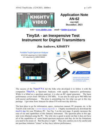
RIGOLHandle AdjustmentTo adjust the handle position of the instrument, please grip the handle by sides andpull it outward. Then, rotate the handle to the desired position. The operatingmethod is shown below.Adjusting the handleViewing Positions2Carrying PositionQuick Guide for DG5000
RIGOLAppearance and DimensionsFront ElevationSide ElevationQuick Guide for DG5000Unit: mmUnit: mm3
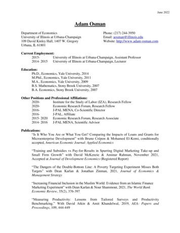
RIGOLFront PanelThe manual illustrates the front panel of the instrument taking the dual-channelmodel for example.2.USB Host3.LCD4.Display e9.Noise10.Arb11.User-defined Key1.Power Key13.Menu Softkey12.Page Up/Down21.Direction Keys22.Numeric Keyboard23.Channel Toggle26.CH1 Output27.CH2 Output24.CH1 Output Control25.CH2 Output ControlFigure 7 Dual-Channel Model Front Panel OverviewFigure 8 Single-Channel Model Front Panel Overview4Quick Guide for DG5000
RIGOL1. Power KeyThe power soft key is used to turn the generator on or off.2. USB HostSupport FAT file format USB flash device, RIGOL TMC digital oscilloscope (DS)and power amplifier (PA). USB flash device: Read the waveform or state files from the USB flash device,or store the current instrument state and edited waveform data into the USBflash device. TMC DS: Seamlessly interconnect with the RIGOL DS that fits the TMCstandard, read and store the waveform data sampled by the DS and displayit nondestructively. PA (optional): Support the RIGOL power amplifier, for example, PA1011.Enable to be configured online and amplify the signal power before output.3. LCD480 272 TFT color LCD is used to display the current function menu andparameters setting, system state and prompt messages.4. Display SwitchFor dual-channel model: Switch between Parameter/Graph display mode.For single-channel model: not available.5. SineGenerate a Sine waveform with frequency from 1 μHz to 350 MHz. When the function is enabled, the backlight of the button turns on. Enable to change Frequency/Period, Amplitude/High Level, Offset/Low Leveland Start Phase of the Sine waveform.6. SquareGenerate a Square waveform with frequency from 1 μHz to 120 MHz and variableduty cycle. When the function is enabled, the backlight of the button turns on. Enable to change Frequency/Period, Amplitude/High Level, Offset/Low Level,Duty Cycle and Start Phase of the Square waveform.7. RampGenerate a Ramp waveform with frequency from 1 μHz to 5 MHz and variablesymmetry. When the function is enabled, the backlight of the button turns on.Quick Guide for DG50005
RIGOL Enable to change Frequency/Period, Amplitude/High Level, Offset/Low Level,Symmetry and Start Phase of the Ramp waveform.8. PulseGenerate a Pulse waveform with frequency from 1 μHz to 50 MHz and variablepulse width and edge time. When the function is enabled, the backlight of the button turns on. Enable to change Frequency/Period, Amplitude/High Level, Offset/Low Level,Pulse Width/Duty Cycle, Leading Edge Time, Trailing Edge Time and Delayof the Pulse waveform.9. NoiseGenerate a Gauss Noise with bandwidth up to 250 MHz. When the function is enabled, the backlight of the button turns on. Enable to change Amplitude/High Level and Offset/Low Level of the Noisewaveform.10. ArbGenerate an arbitrary waveform with frequency from 1 μHz to 50 MHz. Provide two output modes: “Normal” and “Play”. Generate 10 built-in waveforms: DC, Sinc, Exponential Rise, Exponential Fall,ECG, Gauss, Haversine, Lorentz, Pulse and Dual-Tone; generate arbitrarywaveforms from USB flash device; generate arbitrary waveforms editedonline (512 kpts) or through PC software and then downloaded to theinstrument by the users; support wavetable points up to 128 Mpts. When the function is enabled, the backlight of the button turns on. Enable to change Frequency/Period, Amplitude/High Level, Offset/Low Leveland Start Phase of the arbitrary waveform.11. User-defined KeyFor some frequently used menus with “deep” location, users can define them asshortcuts (under the function key Utility). And then, in any operation interface,press the User-defined Key to quickly open and set your desired menu orfunction.12. Page Up/DownOpen the previous or next page of the current function menu.13. Menu SoftkeyPress any softkey to activate the corresponding menu.6Quick Guide for DG5000
RIGOL14. ModulationGenerate modulated waveforms. Provide versatile common modulations anduser defined IQ modulation. Common Modulations: Support internal and external modulations, generateAM, FM, PM, ASK, FSK, PSK and PWM modulated signal. User Defined IQ Modulation: Support internal and external modulation,generate IQ modulated signal.15. SweepGenerate the frequency sweeping signal of Sine, Square, Ramp and ArbitraryWaveforms (except DC). Support three sweep types: Linear, Log and Step. Set Start Hold, End Hold and Return Time. Provide the “Mark” function. When the function is enabled, the backlight of the button turns on.16. BurstGenerate burst waveforms of Sine, Square, Ramp, Pulse and Arbitrary waveform(except DC). Support three burst types: N Cycle, Infinite and Gated. Noise can also be used to generate Gated burst. When the function is enabled, the backlight of the button turns on. In remote mode, press this button to switch to local mode.17. Store/RecallStore/recall the instrument state or user-defined arbitrary waveform data. Support file management system to execute normal file operations. Provide 1 GBytes built-in non-volatile memory (C Disk) and two external USBflash devices (D Disk and E Disk). In addition, files stored in a USB flashdevice can be copied to C Disk for long-term preservation. When the function is enabled, the backlight of the button turns on.18. UtilityProvide some advanced operations, including system parameters setting,waveform saving and printing, functions expanding and the remote controlinterfaces configuration.When the function is enabled, the backlight of the button turns on.19. HelpTo get context help information about any front-panel key or menu softkey, pressQuick Guide for DG50007
RIGOLthis key until it is illuminated and then press the desired key.20. KnobBe used to increase (clockwise) or decrease (anticlockwise) the currenthighlighted number. Also can be used to select file location or switch thecharacter of the soft keyboard when entering file name.21. Direction KeysBe used to switch the digits of the number, the data page and the file locations.22. Numeric KeyboardConsists of numbers (0 9), decimal point (.) and operators ( /-). Notice that, ifa negative required, please input an operator “-” before the numbers. In addition,the decimal point “.” also can be used to switch units quickly.23. Channel ToggleFor dual-channel model: switch and toggle a channel.For single-channel model: not available.24. CH1 Output ControlFor dual-channel model: control the output of CH1. When the output functionenables, the backlight of the button goes on.For single-channel model: trigger “Sweep” and “Burst” manually.25. CH2 Output ControlFor dual-channel model: control the output of CH2. When the output functionenables, the backlight of the button turns on.For single-channel model: control the output of the main channel. When theoutput function enables, the backlight of the button turns on.26. CH1 OutputThis BNC connector is used as an output terminal.For dual-channel model: enable or disable waveform signals generated from[Output] connector corresponding to CH1. The nominal output impedance is 50Ω.For single-channel model: output a TTL-compatible pulse synchronized with themain output. The nominal source impedance is 50 Ω.27. CH2 OutputThis BNC connector is used as an output terminal. The nominal output8Quick Guide for DG5000
RIGOLimpedance is 50 Ω.For dual-channel model: enable or disable waveform signals generated from[Output] connector corresponding to CH2.For single-channel model: output signals of the main channel.CAUTIONOvervoltage protection of the output channel will take effect once any ofthe following conditions is met. Amplitude setting in the generator is greater than 2 Vpp; the inputvoltage is greater than 12.1 V ( 0.1 V) and frequency is lower than10 kHz. Amplitude setting in the generator is lower than or equal to 2 Vpp; theinput voltage is greater than 4.8 V ( 0.1 V) and frequency is lowerthan 10 kHz.The message “OverLoad protect, The output is off!” will appear on thescreen when overvoltage protection takes effect.Quick Guide for DG50009
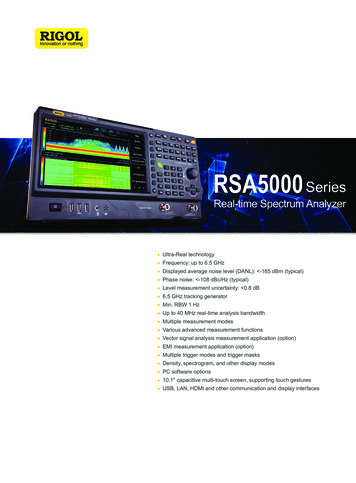
RIGOLRear PanelThe manual illustrates the rear panel of the instrument taking the dual-channelmodel for example.1.Digital Output5.CH2 Q Signal In4.CH1 Q Signal In3.CH2 Mod/I Signal In2.CH1 Mod/I Signal In14.GPIB13.USB Device12.LAN15.USB Host16.Lock Hole9.CH2 ExtTrig In8.CH1 ExtTrig In7.CH2 Sync Out6.CH1 Sync Out10.10MHz In11.10MHz Out17.Power Switch18.Power SocketFigure 9 Dual-Channel Model Rear Panel OverviewFigure 10 Single-Channel Model Rear Panel Overview10Quick Guide for DG5000
RIGOL1.DIGITAL OUTPUTConnect the generator with the “logic signal output module” DG-POD-A(optional). Then, configure specific sequence digital signal in the generator andoutput the signal through the digital module.2.CH1 Mod/I Signal In (Mod/I1)This SMB connector accepts an external Analog modulation signal or In-Phase (I)baseband signal to be used in CH1’s modulation. The nominal input impedanceis 10 kΩ.3.CH2 Mod/I Signal In (Mod/I2)This SMB connector accepts an external Analog modulation signal or In-Phase (I)baseband signal to be used in CH2’s modulation. The nominal input impedanceis 10 kΩ.4.CH1 Q Signal In (Q1)This SMB connector accepts an external Analog/ Quadrature Phase (Q)modulation signal to be used in CH1’s modulation. The nominal input impedanceis 10 kΩ.5.CH2 Q Signal In (Q2)This SMB connector accepts an external Analog/ Quadrature Phase (Q)modulation signal to be used in CH2’s modulation. The nominal input impedanceis 10 kΩ.6.CH1 Sync Out (Sync1)This SMB connector outputs a TTL-compatible pulse synchronized with theoutput of CH1. The nominal source impedance is 50 Ω.7.CH2 Sync Out (Sync2)This SMB connector outputs a TTL-compatible pulse synchronized with theoutput of CH2. The nominal source impedance is 50 Ω.8.CH1 ExtTrig In (ExtTrig1)This SMB connector accepts an external TTL-compatible pulse as the triggerinput of CH1. Besides, it can also be used as the trigger out in Sweep and Burstmode.Quick Guide for DG500011
RIGOL9.CH2 ExtTrig In (ExtTrig2)This SMB connector accepts an external TTL-compatible pulse as the triggerinput of CH2. Besides, it can also be used as the trigger out in Sweep and Burstmode.10. (11.)10MHz In/10MHz OutThese two connectors are used to synchronize generators. The connector[10MHz In] accepts an external 10 MHz clock signal, and the connector [10MHzOut] can output a 10 MHz clock signal generated by the crystal inside thegenerator.19. LANThrough this interface, the generator can be connected to your local network forremote control. An integrated testing system may be built, as the generatorconforms to the LXI-C class standard of LAN-based instrument control.20. USB DeviceThrough this interface, the generator can be connected to a PictBridge printer toprint its screen, or be connected to a PC and controlled via PC software.21. GPIBMeet IEEE-488.2 specification.22. USB HostReference to “USB Host” page 5.23. Lock HoleUse the security lock (please buy it yourself) to lock the generator in fixedlocation.24. Power SwitchConnect or cut off the power supply.25. Power SocketThe generator can accept two types of AC power supply.AC Power Supply: 45-440 Hz, 100-127 V, or 45-60 Hz, 100-240 V.Power Fuse: 250 V, T3A.Power Consumption: less than 125 W.12Quick Guide for DG5000
RIGOLPower on the GeneratorConnect the generator to the AC supply by using the supplied power cord, and thenperform the following steps.1. Turn on the power of the instrumentTurn on the power switch at the rear panel of the instrument.WARNINGTo avoid electric shock, make sure the instrument has been properlygrounded.2. Start-up the instrumentPress down the power key at the front panel. The instrument starts andexecutes self-test and then enters the user interface.Quick Guide for DG500013
RIGOLUser InterfaceThe user interface is usually shown in two modes which are “Parameter” and“Graphic”. The illustration given here will take the “Graphic” mode of theDual-Channel Model for example.Parameter ModeFigure 11 User Interface (Parameter Mode)Graph ModeIn parameter mode, toggle the “Display Switch”to switch to the Graphic Mode.at the upper right of the screen1.StatusBar3.Channel Label4.Freq Disp5.Ampl Disp6.Wave Disp2.CurrentFunction7.Output Cfg8.Menu SoftkeyFigure 12 User Interface (Graphic Mode)14Quick Guide for DG5000
RIGOL1. Status BarIndicate system status. For example, an icondevice has been detected.denotes that a USB flash2. Current FunctionShow the current active function. For example, “Sine” denotes that sine wave hasbeen selected at present.3. Channel Label BarBe divided into two parts which marks the display areas of CH1 and CH2respectively. The currently selected channel label will be highlighted.4. Frequency DisplayDisplay the current waveform frequency in each channel. Press correspondingsoftkey Freq and use the numeric keyboard or knob to modify this parameter.The parameter that can be modified currently will be highlighted.5. Amplitude DisplayDisplay the current waveform amplitude in each channel. Press correspondingsoftkey Ampl and use the numeric keyboard or knob to modify this parameter.The value that can be modified currently will be highlighted.6. Waveform DisplayDisplay the currently selected waveform shape in each channel. The waveform ofthe currently selected channel will be highlighted.7. Output ConfigurationDisplay the current output configuration in each channel, including “Outputresistance” and “Attenuation setting”.8. Menu SoftkeyPress any softkey to activate the corresponding function.Quick Guide for DG500015
RIGOLTo Rack Mount the InstrumentThis generator can be mounted in a standard 19-inch rack cabinet. Pleasedisassemble the cushioning material and handle before the installation.Kit Parts ListNO.NameQty.Part NumberDescription1-1Front Panel1RM-DG-5-011-2Support Board1RM-DG-5-021-3Left Plate1RM-DG-5-031-4Right Plate1RM-DG-5-041-5Fixed Figure2RM-DG-5-052-1M4 Screw19RM-SCREW-01M4*6 Phil-Slot Pan Head Machine Screw Nail2-2M6 Screw4RM-SCREW-02M6*20 Phil-Slot Pan Head Machine Screw Nail2-3M6 Nut4RM-SCREW-03M6*4 Square Machine Female Screw ContainLock Blade16Quick Guide for DG5000
RIGOL2-12-22-3Installation ToolPH2 Phillips Screwdriver (recommended).Quick Guide for DG500017
RIGOLSpace Requirements for InstallationThe following requirements must be fulfilled by the machine cabinet in which theinstrument is mounted. Dimension of the machine cabinet must be standard 19-inch. At least 3U (133.5 mm) space should be provided by the machine cabinet. The depth inside the machine cabinet should not be less than 530 mm.The dimension of the instrument after being mounted is shown below.18Quick Guide for DG5000
RIGOLInstallation ProceduresOnly authorized operators can execute the installation operation. The instrument willbe damaged or installed in rack incorrectly if the installation is not proper.1.Remove the handle: please grip the handle by sides, pull it outward and thenupward.2.Install the right and left plates: align the detents of right and left plates with theopenings on the support board and insert them into the support boardrespectively, then fix them with eight M4 screws.Quick Guide for DG500019
RIGOL3.Place the instrument: align the protection pads of the instrument with thecorresponding holes and then place it on the Support Board.4.Fixed the instrument: Fasten the instrument tightly on the Support Board withtwo Fixed Figures and fixed it with four M4 screws.20Quick Guide for DG5000
RIGOL5.Install the Front Panel: aiming the instrument front panel at the opening of theFront Panel of the machine rack and fix them with four M4 screws.6.Load into the machine cabinet: mount the rack fixed with instrument into astandard 19-inch machine cabinet with four M6 screws and square nuts.7.Post-installation notice: The rack occupies a height of 3U. The holes pointed outby the arrows are the installation holes. Note that they are aligned whileinstalling.Quick Guide for DG500021
RIGOLTo Use the Security LockUse a security lock to lock your generator in a desired location. As shown in thepicture below, align the lock with the lock hole on the generator and insert the lock.Turn the key clockwise to lock the instrument and then pull the key out.22Quick Guide for DG5000
RIGOLTo Use the Built-In HelpTo get context help information about any front-panel key or menu softkey, pressHelp to illuminate the key and then press the desired key to get corresponding help.Pressing Help twice will get the following common help.1. View the last displayed message.2. View error queue of the remote commands.3. Get the help information of a key.4. Generate a basic waveform.5. Generate an arbitrary waveform.6. Generate a modulated waveform.7. Generate a frequency Sweep.8. Generate a Burst waveform.9. IQ (In-Phase/Quadrature) modulation.10. Frequency hopping output.11. Storage management.12. Synchronize multiple Generators.13. Seamlessly connected with the RIGOL DS.14. Get technical support from RIGOL.Quick Guide for DG500023
RIGOLTroubleshootingThis chapter lists the commonly encountered failures and their solutions. When youencounter those problems, please solve them following the corresponding steps. Ifthe problem persists, please contact RIGOL and provide your device information(Utility System Sys Info).1.The screen is still dark (no display) after power on:(1) Check if the power is correctly connected.(2) Check if the power switch is really on.(3) Restart the instrument after finishing the above inspections.(4) If it does not work correctly, contact RIGOL for our service.2.The settings are correct but no waveform is generated:(1) Check if the Signal Line is correctly connected to the Output terminal.(2) Check if the BNC can work correctly.(3) Check the Output button, if it is turned on.(4) Set Power On as “Last” and then restart the instrument after finishing theabove inspections.(5) If it does not work correctly, contact RIGOL for our service.3.The U-disk cannot be recognized:(1) Check if the U-disk can work normally.(2) Make sure the U-disk is USB flash disk. The generator doesn’t support harddrive-based U-disk.(3) Restart the instrument, reinsert the USB device and check it.(4) If the U-disk still does not work normally, please contact RIGOL.24Quick Guide for DG5000
General Care and Cleaning General Care Do not leave or store the instrument exposed to direct sunlight for long periods of time. Cleaning Clean the instrument regularly according to its operating conditions. To clean the exterior surface, perform the following steps: 1. Disconnect the instrument from all power sources. 2.