Transcription
S Geoborwireline core barrelSymmetrix & Elemex – productOperator’scatalogueinstructionsand selection guide
ContentsIntroductionIntroduction 2These instructions are intended for operators of the TerraRocequipment. The aim of the instructions is to provide you withknowledge of how to use the equipment in an efficient and safeway. These instructions also give you advice and tell you howto perform regular maintenance on the equipment. It does notreplace thorough training of operator, it is a complement. Forfurther information concerning service measures, please contactyour nearest TerraRoc representative.1. Product description. 31.1. Description. 31.2. Method 1-7 description. 31.3. Technical data - wireline core barrel. 51.4. Technical data - rods. 51.5. Technical data - drill bits. 62. Operating instructions 72.1. Basic setting of the core barrel. 72.2. Drilling. 82.2.1. Recommended drilling parameters. 82.3. Catching and lifting the inner core barrel . 82.4. Installing inner core barrel (water filled hole). 82.5. Installing inner tube assembly (dry hole). 82.5.1. Using Dry-Hole device as overshot. 92.6. Overload protections - optional safety device. 92.7. Pilot coring 4" (101 mm) hole. 102Always read these instructions carefully and make sure that youunderstand all of them before starting for the first time.The owner of the equipment is granted the permission totake copies of this publication solely for internal use. It isrecommended, however, to order additional copies from TerraRocrepresentative in order to benefit from the latest revision.TerraRoc Ltd reserves the right to make changes in its products inorder to improve design or performance characteristics withoutnotice. The information in this publication is assumed to beaccurate at the time of publication, but is subject to changes inorder to remedy detected deficiencies or to follow changes in theproduct.Any user of this publication is requested to inform TerraRoc aboutdeficiencies found, particularly in matters concerning productsafety.
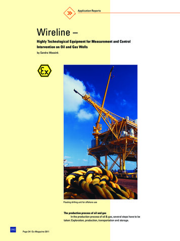
1. ProductdescriptionFig 1.2.1. Method 1–31.1. DescriptionThe TerraRoc S Geobor wireline core barrel with standarddiameter 146 mm was designed for core sampling from hard,to extremely soft and clayey formations, using a wide range ofdrilling methods. It is available in usable lengths of 1.500 m and3.000 m.In general, the S Geobor system is extremely versatile. As a triplecore barrel, i.e. a double core barrel with a plastic liner, it can copewith most coring tasks. Water, fluid mud or air can be used as theflushing medium.S Geobor can be adapted to almost all soil and rock situationsusing different types and shapes of drill bit.Coring is optimised by changing the core lifter (with- or withoutcatch springs), core lifter cases, inner tube assemblies, bits withvarying design, etc.The plastic liner filled with the core sample, can be used forprotection during transport or storage.The S Geobor drilling system is an original TerraRoc design andoffers a number of advantages such as: Stable core barrel head with reliable triple latching Full flexibility in core sampling method 1–5 standard coring,pilot coring, Shelby tube sampling or non coring. Safety installation and recovering of inner tube assembly.The optional “Dry hole device” guarantee the inner tube will beinserted and released only when latched, working in liquid filled –or dry hole.1.2. Method 1–7 description123Method 1123123Method 2Method 31. Core lifter2. Core lifter case3. Core bitMethod 4: Coring in soft varying formations.(Mazier method). (Available on request).For coring in very soft, loose formations with varying layers.Thespring-loaded inner tube assembly is extended to run in front ofthe bit, but is retractable for optimized adaption to the hardnessof the ground and to protect the core lifter case from destruction.For this method, a carbide bit OD/ID 146/109 is used. The corediameter is 102 mm.The inner tube with the core lifter case protrude about 60 mmahead of the bit. The assembly will retract at around 600 kg totalpressure, to the bit front, which means that position of the corelifter case is constantly adjusted to the hardness of the rock. Thiswill minimize the exposure of the sample to the flushing.Fig 1.2.2. Method 4The S Geobor wire line core barrel can be used in many ways, e.g.:Method 1: Coring in hard to medium-hardformationsDrill bit with surface set- or impregnated diamonds, PCD, Corboritor carbide inserts. The cutting diameter of 146 (150) mm gives acore diameter of 102 mm.The drill bits normally have flushing holes through the bit front(face discharge FD), but can also have water channels over the bitfront (channel flush CF, ECF).Method 2: Coring in soft to very softformationsHere, the carbide bit is build divided in two steps,(reamer andpilot). The pilot step cuts the core and the reamer step keep thehole gauge. The flushing fluid comes out between the two steps,thus avoiding flushing out the core. The reamer keep the holediameter of 150 mm. The pilot cuts a core diameter of 102 mm.Core lifter caseMethod 3: Coring in very soft and loose formations, extremelysensitive to flushing.This carbide bit is built in two steps. However the pilot ID allowsthe core lifter case to protrude about 25 mm in front of the bit, asa plunger sleeve, in order to keep the flushing fluid away fromthe core samples. The reamer cuts a hole of 150 mm, the pilottogether with the special protruding core lifter case return a coresample with diameter 102 mm.3
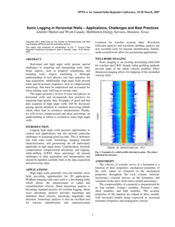
Method 5: “Shelby tube” sampling.Method 7: Packer for water lossUsed for taking samples from very soft and fine cohesion ground(clay etc.)(Lugeon) test and/or fluid collection. (Available on request).The inner tube assembly will be replaced with a non rotatingShelby tube assembly. Samples are collect in front of the bit bypressing the sampler down in the ground as far as the sampletube lebth allow (762/914 mm).The Shelby tube tube return a core sample with diameter 95 mm:– bit size OD/ID 146/102 mm.Note! With this method, there is no rotation, only pressure.Fig 1.2.3. Method 5: Non core drilling method11. SamplerMethod 6: Non core drilling methodIf core drilling will be alternated with non coring the inner tubeassamble is replaced with a non coring inner tube assembly. Thenon coring assemble is designed for 37/8" (98,4 mm) non coring bitwith 23/8" API REG pin connection.The outer tube assemble should be equipped with standardS Geobor bit size (OD/ID 146/102 mm).The S Geobor a strong and unique three latching system, allow7 ton trust load.“Pilot coring” optional alternative with method 6Pilot coring is used for strain measurements in a 4" (102 mm) hole.The non coring bit will be replaced with a core barrel (101T2,101T6 or 101T6S) and a crossover adapter. Pilot coring will returna core sample with smaller diameter from the section where the4" (102 mm) hole is required.Fig 1.2.4. Method 6: Non coring method11. Non coring bit4Fig 1.2.5. Packer Method
1.3. Technical data – wireline corebarrelRods described (Monobloc) are made in one piece.They are cold-drawn and heat-treated.Threads are conical with 3TPI. Surface treated by special coating.Diameter and core diameterDiameter (mm)PartOuter tubeODID139,7128,0Inner tube117,0111,0PVC liner110,0105,6Core102Length and core lengthPartLength (mm)Core length (mm)Core barrel x 1500 mm26001500Core barrel x 3000 mm41003000WeightsPartWeight (kg)Core barrel x 1500 mm101Core barrel x 3000 mm136Inner tube unit x 1500 mm46Inner tube unit x 3000 mm58Outer tube unit x 1500 mm55Outer tube unit x 3000 mm78Core barrel head complete25Overshot (catcher)11Dry hole device15Overload protection complete51.4. Technical data – rodsThe following information applies for S Geobor Monobloc wireline core rods.Technical dataMaterial qualityP-105Yield strength (min.)740 N/mm2Tensile strength (min.)880 N/mm2Expansion after A 5% (min)13 %Recommended make up torque3 KNmMaximum single torque8,2 KNmMaximum pull force445 KNOuter tube diameter139,7 mmInner tube diameter125,5 mmRods are available in 3 lengths as standard:Available rodsLength (mm)Part numberWeight per rodassembly (kg)5008393 0528 001215008393 0528 203530008393 0528-30705
1.5. Technical data – drill bitsMethod 2 (OD 150 mm, ID 102 mm)Various types and designs of drill bit can be used for the S Geoborcore barrel, depending on which method is used and in whatformation drilling is to be carried out. The most common typesand application are described here:Method 1 (OD 146 mm, ID 102 mm)Type / ApplicationPart numberTCI – Tungsten Carbide Insert bit.Two step bit (pilot and reamer). Flushing holes(FD). For soft formation.8372 0941 10Type / ApplicationPart numberTCI – Tungsten Carbide Insert bit.Two step bit (pilot and reamer). For very softformation. With flushing holes (FD).8372 0902 10To be used with Core lifter case3867 2876 00Method 3 (OD 150 mm, ID 110 mm)Type / ApplicationPart number8372 0925 05TCI-Tungsten Carbide Insert bit.Two step bit (pilot and reamer).For very looseformation. With flushing holes (FD).8372 0941 40DPX – Diapax bit with 12 x 13 mm.PCD inserts. Flushing holes (FD). For softformation3702 1901 17To be used with core lifter case (protruding 25mm).3867 2881 00DPX – Diapax bit with 8 x 13 mm.PCD inserts. Flushing channels (CF). For softformation.3702 6391 00CRB – Tungsten Carbide Chip bit.Flushing holes (FD. For soft to medium softformation.TRX – Tripax bits.with PCD inserts. For soft to medium hard formations.- 96 triangular inserts. With flushing holes (FD).3702 5085 00- 60 cubic inserts. With flushing channels (CF).3702 6461 00- 77 cubic inserts. Saw-tooth profile. Withflushing holes (FD).3702 5066 00SS – Surface Set diamond bit.For soft to medium hard formations.- Tapered crown profile, 20/25 spc. Withflushing holes (FD).3702 1901 67- Multi step profile, 20/25 spc. With flushingholes (FD).3702 1901 62CBT TCICBT CRB CFCBT TRX CFCBT DPX FDCBT SS CFCBT IMP FDIMP – Impregnated diamond bit.For hard to very hard formation. With flushing holes (FD).- #4, 6 mm impregnation. With flushing holes(9FD). For soft to medium soft, abrasive, highlyfractured formation.3740 4007 61- #4, 6 mm impregnation. With flushingchannels (12CF). For medium soft to hard,abrasive, fractured formation.3740 4007 63- #6–8, 6 mm impregnation. With flushingchannels (12CF). For medium hard to hard,abrasive mixed formation.3702 6978 00#9, 10 mm impregnation. With flushing holes(12FD). For hard to very hard, slightly abrasiveformation.8370 2300 38Reaming Shell SS Surface diamond set3761 0014 77Look to Terracore catalogue for wider selections of bits.6
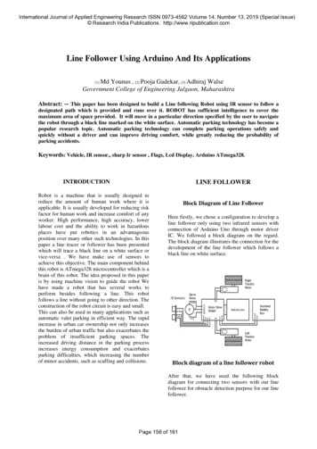
2. OperatinginstructionsFig 2.1.1. Basic setting of the core barrel(See also Product Catalogue 6991 1715 01).12.1. Basic setting of the core barrelCheck that the three latches on the inner core barrel are in theouter position and that they can be pressed in if pressed lightly byhand and that they spring back of their own accord into the initialposition. Mount the core lifter into the core lifter case.7This must be done from the thread side.This ensures the right basic setting for the distance between thecore lifter case and the drill bit.870,5 mmOnce the inner core barrel has been positioned in the outercore barrel and the reaming shell and the drill bit have beenassembled, the distance between the landing shoulder (7, 37021294 00) and the sleeve (9, 3702 1295 00) must be 70,5 mm.If the distance is too less, the flushing fluid will flushing out anddisturb the core sample.910If the distance is too large, the inner core barrel might jam andturn with the outer core barrel. The inner tube core barrel mighteven not latch at all and be pushed upward during drilling. Thecore sample might be lost in the hole and destroyed.1112Setting procedure1. Place one wrench on the locking nut (8, 3702 1293 00).132. Place the other wrench on the shaft (14, 3702 1292).3. Loosen the locking nut by easy hitting it with a hammer.4. Turn the core barrel head to the right reducing the distance5. Turn the core barrel head to the left increasing the distance6. After correctly setting the distance at 70,5 mm, tighten thelocking nut with the wrenches and secure the setting.1. Latch housing7. Landing shoulder14158. Locking nut9. Sleeve14. Shaft16171819207
2.2. DrillingWhen the core barrel and drilling equipment are installed, thedrilling will be performed in the same way as a normal drillingprocess.To achieve an optimum drilling result, the right bit for theformation to be drilled must be selected, and correct drillingparameters used.2.2.1. Recommended drilling parametersBit typeRPMcase and bit (see 2.1. Basic setting of the core barrel). Check thatthe latches are free. The latches must always be in the outerposition and must not show any tendency to “grab”.Insert the complete inner tube into the drill string and let I sink bygravity down to the outer tube core barrel. Once the inner corebarrel has latched into the outer tube core barrel, a vibration orunusual noise can be heard. This shows that the inner core barrelis secured in the working position. Do not confuse this noise withthe noise that can be heard when the inner core barrel passes thejoints in the drill string.TCI – Tungsten Carbide Insert bit50–100CRB – Tungsten Carbide Chip bit80–1502.5. Installing inner tube assembly –(dry hole)DPX – Diapax (PCD) bit50–100Check the core barrel as described in 2.4.TRX – Tripax sawtooth (PCD) bit80–150TRX – Tripax (PCD Geoset)150–300SS – Surface Set diamond bit200–400If the hole contains little or no water, the inner tube assemblycannot be installed in the same way as with a water filled hole.The wire line hoist and optional accessory “Dry hole device” haveto be used.IMP – Impregnated diamond bit300–500Instruction to mount, load and install the Dry hole device.1. Disassemble (catch sleeve 12, P/N 3702 1238 00) from theOvershot 3702 1249 80.Drilling parameterRecommended valueFlushing volume140–250 I/min (water/mud flushing,depending on formation and bit type)Air flushing10–17 m3/min (air flushing dependingon formation and bit type)WOB (weight on bit)Max 90 kN (depending on formation,bit type and method)Core break forceWith core diameter 102 mm in e.g.undisturbed, fault-free dolomite(laboratory data) 40–60 kN (experiencehas however shown that these valuesare lower in practice)2.3. Catching and lifting the innercore barrelIf the core barrel is full, or core block occur, drilling is interrupted.Pull the drill rods up to break the core off. When the top rod jointvisible above the rod holder this rod with water swivel (Kelly)have to be disconnected.The rotation head is swung sideways (if rig design allow) to clearthe box end of the drill rods.Check that the wire line wire is securely fixed to the overshot andlower the overshot down into the drill string. When the overshothas come to a stop, grip the wire and pull, to check whether theovershot is locked to the inner core barrel head.If the overshot is not locked, pull up the overshot approx. onemetre and let it drop. When the overshot is locked to the innercore barrel, pull it up to the surface. Once the inner core barreland the overshot is recovered from the hole, loosen the inner corebarrel from the overshot by pressing the latches together. Removethe core sample from the inner tube. Sometimes it is necessaryto use a rubber hammer to gently tap the inner tube to get theliner with core out. Never use a steel hammer. Dented inner tubescause core blocks.2.4. Installing inner core barrel –(water filled hole)If the inner tube is empty or a second empty inner core barrelis used, check first the core lifter and the core lifter case are notdamaged or worn. Check the correct distance between core lifter82. Attach the dry hole device (13, P/N 3702 1220 80 to the sleeve(11) in the overshot).3. Loosen the nut (1) on the Dry hole device (P/N 3702 1221 00)by turning it to the left.4. Place the complete assembly on to the loading tool(11, P/N 3702 1229 00).5. Press Dry hole device as far down as possible, until the threelatches come out at the side.6. Lock the Dry hole device at this loaded position by turning thenut (1, P/N 3702 1221 00) to the right.7. Install and fix the complete Dry hole device on to the head ofthe inner tube assembly.8. Use the wire line hoist and insert the complete Dry hole deviceand inner tube assembly into the drill rod. Stop the installationjust when the nut (1, P/N 3702 1221 00) still available andvisible above the end of the top rod.9. Loosen the nut by turning left until you hear a snap from thereleased latches in the Dry hole device. The inside of the rodwill now prevent the Dry hole device releasing from the innertube. WARNING, Risk for dropping the inner tube assembly ifDry Hole device is too far up.10. Continue to install the complete assembly with the wire linehoist, until you reach the final position in the core barrel outertube.11. When the inner tube is established in correct position thedry hole device will automatically release from the inner tubeassembly, only in this position.Installing the inner tube assembly with the Dry hole device willgive you a guaranteed indication, that the inner tube is in correctposition.
2.5.1. Using Dry hole device as overshotAfter attaching the Dry hole installation device as described in2.5., the Dry hole device does not need to be removed. The Dryhole device is recommended to be used as over shot to catch theinner tube once the inner tube assembly should be retrieved.Fig 2.5.1. Installing inner tube assembly2.6. Overload protection – optionalsafety deviceThe overload protection prevents the wire to brake, if the innertube assembly and overshot get stuck in the rods.Instruction to assemble the Overload protection.1. Replace the coupling (10, 3702 1247 00) in the overshot 37021249 80 with the complete overload protection 3702 1250 80.(See also Product Catalogue 6991 1715 01).2. If Dry hole device used, install overload protection as above(pos.1) and repeat installation procedure (1–6 in section 1.5).123Fig 2.6. Overload protection.468113. Adjustment of release pressure: Tighten or losen the lock nut(20, 0291 1114 00) to get correct release pressure. Recommendedto test the setting on surface.(See also Product Catalogue 6991 1715 01).71Overload protection3702 1250 80293412681171091312Overshot 3702 1249 801120121Overshot 3702 1249 808910711Dry hole device 3702 1220 801. Load the Dry hole device (repeat procedure 1–6 in section 2.5.).2. The loaded Dry hole device will be utilized as overshotassembly.3. On surface the Dry hole device can be released from innertube assembly by pressing in three core barrel head latches.Recommended to use latch ompression wire –Part No. 3702 1438 00).9
2.7. Pilot coring 4" (101 mm hole)Fig 2.7. Pilot coring.Brief description of procedure(See also Product Catalogue 6991 1715 01).With Method 6, either non coring bit or a core barrel equipmentcan be used. With pilot core equipment, a 101T6/T2 core barrel isused in to be installed through the 102 mm inner diameter in theS GEOBOR bit.Application of a "measurement process" in a 4" (101 mm) hole canbe as follow:1. S Geobor-S Method I used to drill 146 mm diameter hole with102 mm diameter core size.2. A strain measurement (dilation) is to be carried out at desireddepth.3. The inner tube assembly is pulled out.4. Rods with core barrel outer tube are lifted about 2–3,5 m frombottom.5. Non coring assembly is completed with an adapter to 101 mmcore barrel assembly.6. Complete assembly in pos 5. installed with Dry hole device andwire line hoist into the rods.7. Drilling is carried out by rotating S Geobor rods.8. 101T6 core barrel is pulled out after 1,5 m (3 m) pilot coringdistance.Core recovered and measurement can be carried out.Replace the 101 mm core barrel and adapter with a 37/8" noncoring bit, to ream up the pilot cored length to S (146 mm) holesize.S Geobor inner core barrel installed and further full size coringcan be carried out.10
Notes11
Subjected to alterations without prior notice. TerraRoc Tools AB. All rights reserved. 2019.10.9866 0136 01Customized Geotechnical Solutions.Full range of drilling tools and consumables for casing advancement systems,down-the-hole hammers and core drilling, all customized for your needs.terrarocdrilling.comFinlandPihtisulunkatu 1 A33330 TampereFinlandUK4 - 6 South Lumley Street,Grangemouth FK3 8BT,Scotland,USA7500 Shadwell Drive,Roanoke, Virginia, 24019USA
The TerraRoc S Geobor wireline core barrel with standard diameter 146 mm was designed for core sampling from hard, to extremely soft and clayey formations, using a wide range of drilling methods. It is available in usable lengths of 1.500 m and 3.000 m. In general, the S Geobor system is extremely versatile. As a triple