Transcription
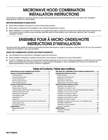
MICROWAVE HOOD COMBINATIONINSTALLATION INSTRUCTIONSThis product is suitable for use above electric or gas cooking products up to and including 36" (91.4 cm) wide. See the “InstallationRequirements” section for further notes.These installation instructions cover different models. The appearance of your particular model may differ slightly from the illustrationin these installation instructions.Table of ContentsMICROWAVE HOOD COMBINATION SAFETY.1INSTALLATION REQUIREMENTS.2Tools and Parts.2Remove Cardboard Template.2Location Requirements.2Product Dimensions.3Electrical Requirements.3INSTALLATION INSTRUCTIONS.4Remove Mounting Plate.4Rotate Blower Motor.4Locate Wall Stud(s).6Mark Rear Wall.7Drill Holes in Rear Wall.7Attach Mounting Plate to Wall.8Prepare Upper Cabinet.8Install Damper Assembly.9Install the Microwave Oven.9Complete Installation.10VENTING DESIGN SPECIFICATIONS.11ASSISTANCE.12Replacement Parts.12Accessories.12MICROWAVE HOOD COMBINATION SAFETYYour safety and the safety of others are very important.We have provided many important safety messages in this manual and on your appliance. Always read and obey all safetymessages.This is the safety alert symbol.This symbol alerts you to potential hazards that can kill or hurt you and others.All safety messages will follow the safety alert symbol and either the word “DANGER” or “WARNING.”These words mean:DANGERWARNINGYou can be killed or seriously injured if you don't immediatelyfollow instructions.You can be killed or seriously injured if you don't followinstructions.All safety messages will tell you what the potential hazard is, tell you how to reduce the chance of injury, and tell you what canhappen if the instructions are not followed.W10918334A
INSTALLATION REQUIREMENTSTools NeededTools and PartsRemove Cardboard TemplateGather the required tools and parts before starting installation.Read and follow the instructions provided with any toolslisted here. Measuring tape Diagonal wire cutting pliers Pencil Stud finder Masking tape orthumbtacks ScissorsM\zn" socket wrench(or box wrench) forZ\v" x 2" lag screws No. 2 Phillips screwdriver No. 3 Phillips screwdriverfor Z\v - 20 x 3" bolts Drill C\zn" (5 mm), C\," (10 mm),B\," (16 mm) drill bits C\v" (19 mm) hole saw The cardboard piece from the top of the microwave ovenpackaging is perforated. The piece inside the perforationis for use as a rear wall template.1. Cut along the perforation to separate the template from therest of the cardboard packaging.2. Set the cardboard template to the side and refer to it duringthe “Mark Rear Wall” part of installation.Location Requirements1½" (3.8 cm) diam. holedrill bit for wood or metalcabinet Keyhole saw Caulking gun andweatherproof caulkingcompound Duct tapeCheck the opening where the microwave oven will be installed.The location must provide: Minimum installation dimensions. See the “InstallationDimensions” illustration. Minimum one 2" x 4" (50.8 x 101.6 mm) wood wall stud andminimum C\," (10 mm) thickness drywall or plaster/lath withincabinet opening. Support for weight of 150 lbs (68 kg) which includesmicrowave oven and items placed inside the microwaveoven and upper cabinet.Grounded electrical outlet inside upper cabinet. See the“Electrical Requirements” section.NOTES:Parts Supplied For information on reordering, see the “Replacement Parts”section.NOTE: The hardware items listed here are for wood studs.For other types of wall structures, be sure to use appropriatefasteners. If installing the microwave oven near a left sidewall, makesure there is at least 6" (15.2 cm) of clearance between thewall and the microwave oven so that the door can open fully. Some cabinet and building materials are not designed towithstand the heat produced by the microwave oven forcooking. Check with your builder or cabinet supplier to makesure that the materials used will not discolor, delaminate, orsustain other damages.ABDCEFGHSpecial RequirementsFor Wall Venting Installation Only:Cutout must be free of any obstructions so that the vent fitsproperly and the damper blade opens freely and fully.For Roof Venting Installation Only: A.B.C.D.E.F.G.H.C\zn-24 x 3" round-head bolts (2)Z\v-20 x 3" flat-head bolts (2)Washers (2)C\zn" toggle nuts (2)Z\v" x 2" lag screws (2)Sheet metal screws (2)Power supply cord bushing (1)Damper assembly (for wall orroof venting)Not Shown: Upper cabinet template Mounting plate (attached toback of microwave oven) Cardboard template (part ofpackaging) Aluminum grease filters Charcoal filters (Dependingon model, charcoal filters maynot be included. See UserInstructions.)NOTE: Depending on model, aluminum grease filter and charcoalfilter may be combined.Materials Needed 2Standard fittings for wall or roof venting. See the “VentingDesign Specifications” section. If you are using a rectangular-to-round transition piece,the 3" (7.6 cm) clearance needs to exist above the microwaveoven so that the damper blade can open freely and fully.See “Rectangular to Round Transition” illustration in the“Venting Design Specifications” section.
Installation DimensionsElectrical RequirementsNOTE: The grounded 3 prong outlet must be inside the uppercabinet. See the “Electrical Requirements” section.AWARNINGB12" (30.5 cm) min.14" (35.6 cm) max.upper cabinet andside cabinet depth30"(76.2 cm)min.Electrical Shock Hazard30"(76.2 cm)typical*Plug into a grounded 3 prong outlet.Do not remove ground prong.Do not use an adapter.Do not use an extension cord.66" (167.6 cm) min.Failure to follow these instructions can result in death,fire, or electrical shock.Observe all governing codes and ordinances.Required:A 120-volt, 60 Hz, AC-only, 15- or 20-amp electrical supplywith a fuse or circuit breakerRecommended: A time-delay fuse or time-delay circuit breaker A separate circuit serving only this microwave ovenGROUNDING INSTRUCTIONSA. 2" x 4" wall studB. Grounded 3 prong outlet*30” (76.2 cm) is typical for 66” (167.6 cm) installation height.Exact dimensions may vary depending on type of range/cooktop below.Product Dimensions16¹ ₄"(41.3 cm)17¹ ₈"(43.5 cm) /- ³ ₁₆"(0.5 cm) For all cord connected appliances:The microwave oven must be grounded. In the event ofan electrical short circuit, grounding reduces the risk ofelectric shock by providing an escape wire for the electriccurrent. The microwave oven is equipped with a cordhaving a grounding wire with a grounding plug. The plugmust be plugged into an outlet that is properly installedand grounded.WARNING: Improper use of the grounding plug canresult in a risk of electric shock. Consult a qualifiedelectrician or serviceman if the grounding instructions arenot completely understood, or if doubt exists as to whetherthe microwave oven is properly grounded.Do not use an extension cord. If the power supply cord istoo short, have a qualified electrician or serviceman installan outlet near the microwave oven.Upto(42 16³ ₄".5 cm)*29⁷ ₈"m)(76.0 cSAVE THESE INSTRUCTIONS*Overall depth of product will vary slightly depending ondoor design.3
INSTALLATION INSTRUCTIONS3. Remove 2 screws attaching blower motor to backof microwave oven.Remove Mounting PlateDepending on your model, the mounting plate may be inthe foam packaging or it may be attached to the back ofthe microwave oven.NOTE: To avoid possible damage to the work surface, cover thework surface.1. Remove any remaining contents from the microwave ovencavity.2. If the mounting plate is attached to the back of the microwaveoven, remove it and set it aside.3. Tape the microwave oven door closed so that door does notswing open while the microwave oven is being handled.NOTE: To avoid damage to the microwave oven, do not gripor use the door or door handle while the microwave oven isbeing handled.AA. Screws (in recessed holes)4. Lift blower motor out of microwave oven.ARotate Blower MotorThe microwave oven is set for recirculation installation. For wallor roof venting, changes must be made to the venting system.NOTE: Skip this section if you are using recirculation installation.Keep the damper assembly in case the venting method ischanged, or the microwave oven is reinstalled in anotherlocation where wall or roof venting may be used.Wall Venting Installation OnlyA. Blower motor1. Remove screws attaching damper plate to top of microwaveoven exterior. Slide damper plate toward the front of themicrowave oven and lift up.5. Rotate blower motor 180 so that exhaust ports face the backof microwave oven and lower blower motor back into themicrowave oven.AABA. ScrewsB. Damper plate2. Keep damper plate and screws together and set aside.4A. Exhaust port6. Reattach blower motor to back of microwave ovenwith 2 screws removed in Step 3.
7. Reattach damper plate. Make sure damper plate tabs areinserted into the slots in the top of the microwave oven.BA6. Reattach blower motor to back of microwave oven with 2screws removed in Step 3 of “Wall Venting Installation Only.”Securely tighten screws.NOTE: If blower motor is not correctly oriented, the 2 screwsremoved in Step 3 cannot be reattached to the microwave oven.7. Reattach damper plate. Make sure damper plate tabs areinserted into the slots in the top of the microwave oven.CBADCA.B.C.D.Damper plateScrewsDamper plate tabsSlotsD8. Secure damper plate with 2 screws removed in Step 1.Roof Venting Installation Only1.2.3.4.5.Repeat Step 1 from “Wall Venting Installation Only.”Repeat Step 2 from “Wall Venting Installation Only.”Repeat Step 3 from “Wall Venting Installation Only.”Repeat Step 4 from “Wall Venting Installation Only.”Rotate blower motor so that exhaust ports face the topof microwave oven and flat sides of blower motor faceback of microwave oven. Lower blower motor back intomicrowave oven.A.B.C.D.Damper plateScrewsDamper plate tabsSlots8. Secure damper plate with 2 screws removed in Step 1 of“Wall Venting Installation Only.”AA. Exhaust portIMPORTANT: If blower motor is not positioned with flat sidesfacing the back of the microwave oven (as shown), performancewill be poor.5
Locate Wall Stud(s)NOTE: If no wall studs exist within the cabinet opening, do notinstall the microwave oven.See illustrations in “Possible Wall Stud Configurations.”1. Using a stud finder, locate the edges of the wall stud(s) withinthe opening.2. Mark the center of each stud and draw a plumb line downeach stud center. See illustrations in “Possible Wall StudConfigurations.”Possible Wall Stud ConfigurationsThese depictions show examples of preferred installation configurations with the mounting plate.No Wall Studs at End HolesNo Wall Studs at End HolesFigure 1Figure 2BCDCAAEFECDAAEFENOTE: If wall stud is within 6" (15.2 cm) of the vertical centerline(see “Mark Rear Wall” section), only recirculation or roof ventinginstallation can be done.Wall Stud at End HoleWall Studs at End HolesFigure 3Figure 4BDAA,DEECFCA.B.C.D.E.F.6BBA,DA,DEECFCEnd holes (on mounting plate)Cabinet opening vertical centerlineWall stud centerlinesHoles for lag screwsSupport tabsMounting plate center markers
Mark Rear WallThe microwave oven must be installed on a minimum of 1 wallstud, preferably 2, using a minimum of 1 lag screw, preferably 2.1. Using measuring tape, find and clearly mark the verticalcenterline of the opening.6. Holding the mounting plate in place, find the wall studcenterline(s) drawn in Step 2 of “Locate Wall Stud(s)” andmark at least 1, preferably 2 hole(s) through the mountingplate, closest to the wall stud centerline(s). See figures 1, 2,and/or 3 in “Possible Wall Stud Configurations” in the “LocateWall Stud(s)” section. The blackened holes in the shadedareas are ideal hole locations.7. Set the mounting plate aside.Wall Venting Installation OnlyAUpper cabinet bottom³ ₈" (1 cm)A. Centerline2. Align the center markers on the cardboard template (cartontop cap) to the centerline on the wall, making sure it is level,and that the top of the cardboard template is butted upagainst the bottom edge of the upper cabinet.NOTES:If the front edge of the upper cabinet is lower than the backedge, lower the cardboard template so that its top is levelwith the front edge of the cabinet. If the cardboard template is damaged or unusable, measureand mark the wall with the dimensions described in Step 4. DACBA. Rear wallB. Cardboard templateC. Top of cardboard template mustalign with front edge of cabinet.D. Front edge of upper cabinetUpper cabinet bottomCenterline14¹ ₈"(35.9 cm)Mounting plate end hole 17¹ ₄"(43.8 cm)14¹ ₈"(35.9 cm)Bottom of mounting plateThe bottom edge line must be 17¹ ₄" (43.8 cm) from thebottom of the upper cabinet and must be level.The end holes must be 15³ ₄" (40.0 cm) from the bottom edgeof the upper cabinet and must be on a level line with eachother. They must each be 14¹ ₈" (35.9 cm) from the centerline.5. With the support tabs facing forward (see illustrations in the“Locate Wall Stud(s)” section), align the mounting plate centermarkers to the centerline on the wall, making sure its bottomedge is aligned to the horizontal line drawn in Step 3 and thatthe end holes are properly marked. Make sure the mountingplate is level. 6" (15.2 cm)Centerline6" (15.2 cm)8. Mark the centerline C\," (1 cm) down from the bottom edge ofthe upper cabinet.9. Using measuring tape, measure out 6" (15.2 cm) on bothsides of the centerline, and mark.10. Measure down 4" (10.2 cm) from the mark made in Step 8and mark.11. Using a straightedge, draw the 2 horizontal, level linesthrough the marks made in steps 8 and 10.12. Draw the 2 vertical plumb lines down from the marks madein Step 9 to complete the 12" x 4" (30.5 x 10.2 cm) rectangle.This is the venting cutout area.13. Cut a C\v" (19 mm) hole in one corner of the cutout area.14. Using a keyhole saw, cut out the venting cutout area.Drill Holes in Rear Wall3. Holding the cardboard template in place, mark both holesin the lower corners and draw a horizontal line across thebottom edge of the cardboard template. These represent themounting plate’s end holes and bottom edge.4. Remove the cardboard template and check the markings:15³ ₄"(40.0 cm)4" (10.2 cm)In addition to being installed on at least 1 wall stud, the mountingplate must attach to the wall at both end holes. If the end holesare not over wall studs, use two C\zn-24 x 3" round-head bolts withtoggle nuts; if 1 end hole is over a wall stud, use 1 lag screw andone C\zn-24 x 3" round-head bolt with toggle nut; or if both endholes are over wall studs, use 2 lag screws. Following are3 installation configurations.Installation for No Wall Studs at End Holes(Figures 1 and 2)1. Drill B\," (16 mm) holes through the wall at both end holesmarked in Step 3 of “Mark Rear Wall.”2. Drill C\zn" (5 mm) hole(s) into the wall stud(s) at the hole(s)marked in Step 6 of “Mark Rear Wall.” Refer to figures 1 and2 in “Possible Wall Stud Configurations” in the “Locate WallStud(s)” section.Installation for Wall Stud at One End Hole (Figure 3)1. Drill a C\zn" (5 mm) hole into the wall stud at the end holemarked in Step 3 of “Mark Rear Wall.”2. If installing on a second wall stud, drill a C\zn" (5 mm) hole intothe wall stud at the other hole marked in Step 6 of “Mark RearWall.” Refer to Figure 3 in “Possible Wall Stud Configurations”in the “Locate Wall Stud(s)” section.3. Drill a B\," (16 mm) hole through the wall at the other end hole.Installation for Wall Studs at Both End Holes (Figure 4)1. Drill C\zn" (5 mm) holes into the studs at the end holes markedin Step 3 of “Mark Rear Wall.”7
Attach Mounting Plate to WallNOTE: Secure the mounting plate to the wall at both end holesdrilled into the wall studs and/or drywall using either C\zn-24 x 3"round-head bolts and toggle nuts or Z\v x 2" lag screws.Refer to illustrations in “Possible Wall Stud Configurations” in the“Locate Wall Stud(s)” section.No Wall Studs at End Holes (Figures 1 and 2)NOTE: The mounting plate must be secured to the wall onat least 1 wall stud as well as at both ends.1. With the support tabs of the mounting plate facing forward,insert C\zn-24 x 3" round-head bolts through both end holes ofmounting plate.2. Start toggle nuts on bolts from the back of the mountingplate. Leave enough space for the toggle nuts to gothrough the wall and to open.BAWall Stud at One End Hole (Figure 3)1. With the support tabs of the mounting plate facing forward,insert a C\zn-24 x 3" round-head bolt through the end hole thatfits over the B\," (16 mm) hole drilled in Step 3 of “Installationfor Wall Stud at One End Hole” in the “Drill Holes in RearWall” section.2. Start a toggle nut on the bolt from the back of the mountingplate. Leave enough space for the toggle nut to go throughthe wall and to open.3. Position mounting plate on the wall.4. Push the bolt with toggle nut through the drywall and fingertighten the bolt to make sure toggle nut has opened againstdrywall.5. Insert a lag screw into the remaining end hole.6. If installing on a second wall stud, insert a lag screw into theother hole drilled in Step 2 of “Installation for Wall Stud atOne End Hole” in the “Drill Holes in Rear Wall” section.7. Check alignment of mounting plate, making sure it is level.8. Securely tighten the lag screw(s) and bolt.Wall Studs at Both End Holes (Figure 4)CA. C\zn-24 x 3" round-head boltB. Mounting plateC. Spring toggle nutC1. Disconnect power to outlet.2. Remove all contents from upper cabinet.3. Place Upper Cabinet Template against the bottom of theupper cabinet and attach with tape or thumbtacks. Makesure the template centerline aligns with the vertical centerlineon the rear wall.The “rear wall” arrows must be against the rear wall so thatthe holes cut into the upper cabinet align with the holes in thetop of the microwave oven.NOTES: BDA.B.C.D.Position mounting plate on the wall.Insert lag screws into both end holes.Check alignment of mounting plate, making sure it is level.Securely tighten the lag screws.Prepare Upper Cabinet3. Position mounting plate on the wall.4. Push the 2 bolts with toggle nuts through the drywall andfinger tighten the bolts to make sure toggle nuts have openedagainst drywall.A1.2.3.4.C\zn-24 x 3" round-head boltMounting plateSpring toggle nutDrywallIf the upper cabinet has a frame around it, trim the templateedges so that it fits inside the frame, against the uppercabinet bottom. The template has trim lines to use as guides.If the wall behind the microwave oven (as installed) has apartial wall covering (for example, tile backsplash), be surethe “Rear Wall” arrows align to the thickest part of the rearwall (for example, the thickness of the tiles rather than thedrywall).4. Make sure the 10" (25.4 cm) dimension from the rear wall topoints “D” and “E” on the template is maintained. 5. Insert lag screw(s) into the hole(s) drilled into wall stud(s) inStep 2 of “Installation for No Wall Studs at End Holes” in the“Drill Holes in Rear Wall” section.6. Check alignment of mounting plate, making sure it is level.7. Securely tighten all lag screws and bolts.Upper-cabinet templateD810"(25.4 cm)EGF10"(25.4 cm)
5. Cut the 1¹ ₂" (3.8 cm) diameter hole at the circularshaded area “G” on the template. This hole is forthe power supply cord.NOTE: If upper cabinet is metal, the supply cord bushing needsto be installed around the supply cord hole as shown.1. Remove the 2 packing spacers from the top of the vent grillebefore using the microwave oven.ABAA. Metal cabinetB. Power supply cord bushing6. Drill C\," (10 mm) holes at points “D” and “E” on the template.These are for two Z\v-20 x 3" bolts and washers used tosecure the microwave oven to the upper cabinet.For Roof Venting Installation OnlyA. Packing spacers (2)2. Place a washer on each Z\v-20 x 3" flat-head bolt and placeinside upper cabinet near the C\," (10 mm) holes.3. Make sure the microwave oven door is closed andtaped shut.7. Cut C\v" (19 mm) hole at one corner of the shaded rectangulararea “F” on Upper Cabinet Template.8. Using a keyhole saw, cut out the rectangular area.Install Damper Assembly(for wall venting only)1. Check that damper blade moves freely and opens fully.2. Position the damper assembly on the back of the microwaveoven so that the damper blade hinge is at the top and thedamper blade opens away from the microwave oven.AB CD4. Using 2 or more people, lift microwave oven and hang it onsupport tabs at the bottom of mounting plate.NOTE: To avoid damage to the microwave oven, do not gripor use the door or door handle while the microwave oven isbeing handled.AA.B.C.D.Back of microwave ovenDamper assemblyDamper bladeSheet metal screws3. Secure damper assembly with 2 sheet metal screws.BA. Mounting plateB. Support tabs5. With front of microwave oven still tilted, thread power supplycord through the power supply cord hole in the bottom of theupper cabinet.Install the Microwave OvenWARNINGExcessive Weight HazardUse two or more people to move and installmicrowave oven.Failure to do so can result in back or other injury.IMPORTANT: The control side of the microwave oven is theheavy side. Handle the microwave oven gently.6. Rotate microwave oven up toward upper cabinet.NOTE: If venting through the wall, make sure the damperassembly fits easily into the vent in the wall cutout.9
7. Push microwave oven against mounting plate and holdin place.NOTE: If microwave oven does not need to be adjusted, skipsteps 7 through 9.8. If adjustment is required, rotate microwave oven downward.Using 2 or more people, lift microwave oven off of mountingplate and set aside on a covered surface.9. Loosen mounting plate screws. Adjust mounting plate andretighten screws.10. Repeat steps 3 through 6.11. With the microwave oven centered, and with at least oneperson holding it in place, insert bolts through upper cabinetinto microwave oven. Tighten bolts until there is no gapbetween upper cabinet and microwave oven.NOTES:2. Connect vent to damper assembly.ASome upper cabinets may require bolts longer or shorterthan 3" (7.6 cm). Longer or shorter bolts are available at mosthardware stores. A. VentB. Damper assembly (under vent)Overtightening bolts may warp the top of the microwaveoven. To avoid warping, wood filler blocks (installer toprovide) may be added. The blocks must be the samethickness as the space between the upper cabinet bottomand the microwave oven. BComplete Installation1. Install filters. Refer to the User Instructionsfor filter placement.AWARNINGElectrical Shock HazardPlug into a grounded 3 prong outlet.Do not remove ground prong.A. BoltsDo not use an adapter.For Roof Venting Installation OnlyDo not use an extension cord.1. Insert damper assembly through the cabinet cutout sothat the long tab of the damper assembly slides underthe raised tabs of the damper plate. Then secure withsheet metal screw.NOTE: The screw cannot be installed if the damper assemblyis not positioned as shown.ADBEFA.B.C.D.E.F.10CRaised tabsDamper assemblySheet metal screwUpper cabinet cutoutLong tabDamper plateFailure to follow these instructions can result in death,fire, or electrical shock.2. Plug microwave oven into grounded 3 prong outlet.3. Reconnect power.4. Check the operation of microwave oven by placing 1 cup(250 mL) of water on the turntable and programming a cooktime of 1 minute at 100% power. Test vent fan and exhaustby operating the vent fan.5. If the microwave oven does not operate: Check that a household fuse has not blown, or thata circuit breaker has not tripped. Replace the fuseor reset the circuit breaker. If the problem continues,call an electrician. Check that the power supply cord is plugged intoa grounded 3 prong outlet. See the User Instructions for troubleshooting information.Installation is now complete.Save Installation Instructions for future use.
VENTING DESIGN SPECIFICATIONSThis section is intended for architectural designer and builder/contractor reference only.NOTES: Vent materials needed for installation are not provided withmicrowave hood combination. We do not recommend using a flexible metal vent. To avoid possible product damage, be sure to vent airoutside, unless using recirculation installation. Do not ventexhaust air into concealed spaces, such as spaces withinwalls or ceilings, attics, crawl spaces, or garages.For optimal venting installation, we recommend: Using roof or wall caps that have back draft dampers Using a rigid metal vent Using the most direct route by minimizing the length of thevent and number of elbows to provide efficient performance Using uniformly sized vents Using duct tape to seal all joints in the vent system Using caulking compound to seal exterior wall or roofopening around capRectangular-to-Round TransitionNOTE: The minimum 3" (7.6 cm) clearance must exist betweenthe top of the microwave oven and the rectangular to roundtransition piece so that the damper can open freely and fully.ABCDENot installing 2 elbows together for optimal hoodperformanceIf venting through the wall, be sure that there is proper clearancewithin the wall for the damper to open fully.If venting through the roof, and rectangular-to-round transitionis used, be sure there are at least 3" (7.6 cm) of clearancebetween the top of the microwave oven and the transitionpiece. See “Rectangular-to-Round Transition” illustration. A.B.C.D.E.Roof cap6" (15.2 cm) min. diameter round ventElbow (for wall venting only)Wall cap3¹ ₄" x 10" to 6" (8.3 x 25.4 cm to 15.2 cm)rectangular to round transition pieceF. Vent extension piece, at least 3" (7.6 cm) highRecommended Standard FittingsThe following length equivalents are for use when figuring ventlength. See the examples in “Recommended Vent Length.”ARoof ventingBCRoof capDWall ventingF3" (7.6 cm)Wall capEFGA. Rectangular-to-round transition piece: 3¹ ₄" x 10" to 6" 5 ft(8.3 x 25.4 cm to 15.2 cm 1.5 m)B. Roof cap: 3¹ ₄" x 10" 24 ft (8.3 x 25.4 cm 7.3 m)C. 90 elbow: 3¹\₄" x 10" 25 ft (8.3 x 25.4 cm 7.6 m)D. 90 elbow: 6" 10 ft (15.2 cm 3 m)E. Wall cap: 3¹ ₄" x 10" 40 ft (8.3 x 25.4 cm 12.2 m)F. 45 elbow: 6" 5 ft (15.2 cm 1.5 m)G. 90 flat elbow: 3¹ ₄" x 10" 10 ft (8.3 x 25.4 cm 3 m)11
Recommended Vent LengthA 3¹ ₄" x 10" (8.3 x 25.4 cm) rectangular or 6” (15.2 cm) roundvent should be used.The total length of the vent system including straight vent,elbow(s), transitions, and wall or roof caps must not exceedthe equivalent of 140 ft (42.7 m) for either type of vent. See the“Recommended Standard Fittings” section for equivalent lengths.For best performance, use no more than three 90 elbows.To calculate the length of the system you need, add theequivalent lengths of each vent piece used in the system.See the following examples:6" (15.2 cm) vent system 73 ft (22.2 m) totalA6 ft (1.8 m)2 ft(0.6 m)3¹ ₄" x 10" (8.3 x 25.4 cm) vent system 73 ft (22.2 m) totalACBA.B.C.D.6 ft (1.8 m)2 ft(0.6 m)CA. One 3¹ ₄" x 10” (8.3 x 25.4 cm) 90 elbow 25 ft (7.6 m)B. 1 wall cap 40 ft (12.2 m)C. 2 ft (0.6 m) 6 ft (1.8 m) straight 8 ft (2.4 m)BDTwo 90 elbows 20 ft (6.1 m)1 wall cap 40 ft (12.2 m)1 rectangular-to-round transition piece 5 ft (1.5 m)2 ft (0.6 m) 6 ft (1.8 m) straight 8 ft (2.4 m)If the existing vent is round, a rectangular-to-round transitionpiece must be used. In addition, a rectangular 3" (7.6 cm)extension vent between the damper assembly and rectangularto-round transition piece must be installed to keep the damperfrom sticking.ASSISTANCECall your authorized dealer or service center. When you call, youwill need the microwave oven model number and serial number.Both numbers can be found on the model and serial numberplate, which is located behind the microwave oven door on thefront frame of the microwave oven.If you need additional assistance, call us at our toll-free numberor visit our website listed in the User Guide.AccessoriesFiller Panel Kits are available from your dealer to use wheninstalling this microwave oven in a 36" (91.4 cm) or 42"(106.7 cm) wide opening. The filler panels come in pairs.Each panel is 3" (7.6 cm) wide.Replacement PartsIf any of the installation hardware needs to be replaced, call us atour toll-free number listed in the User Guide.Following is a list of available replacement parts. You will needyour model number located on the front facing of the microwaveoven opening, behind the door. Damper assembly Mounting plate Upper cabinet template Mounting Screw Kit (includes parts A through G in “PartsSupplied” in the “Tools and Parts” section)AA. Filler panelsFiller Panel scuitStainless SteelAlmondSee your authorized dealer or service center for details.W10918334ASP PN W10918351 2016. All rights reserved.9
MICROWAVE HOOD COMBINATION INSTALLATION INSTRUCTIONS This product is suitable for use above electric or gas cooking products up to and including 36" (91.4 cm) wide.