Transcription
MICROWAVE HOOD COMBINATIONINSTALLATION INSTRUCTIONSThis product is suitable for use above electric or gas cooking products up to and including 24" (61.0 cm) wide. See “InstallationRequirements” section for further details.BEFORE BEGINNING PLEASE NOTE: Read these Installation Instructions in their entirety before starting. Vent system is required for this installation. See “Venting Requirements” section. When installation is complete, the microwave oven’s galvanized upper component housing will be visible above the microwave oven.The housing may be covered using a stainless steel filler panel (not provided) or with customized cabinetry. See “CompleteInstallation” section.ENSEMBLE FOUR À MICRO-ONDES/HOTTEINSTRUCTIONS D’INSTALLATIONCe produit peut être installé au-dessus de produits de cuisson électriques ou à gaz d'une largeur maximale de 24" (61 cm). Voir la section“Exigences d'installation” pour plus de détails.AVANT DE COMMENCER, NOTER LES POINTS SUIVANTS : Lire la totalité de ces instructions d'installation avant de commencer. Cette installation nécessite un système d'évacuation. Voir la section “Exigences du circuit d'évacuation”. Une fois l'installation terminée, le compartiment supérieur galvanisé du four à micro-ondes sera apparent au-dessus du four à microondes. Le compartiment peut être recouvert d'un panneau de remplissage en acier inoxydable (non fourni) ou d'un élément deplacard personnalisé. Voir la section “Achever l'installation”.Table of Contents / Table des matièresMICROWAVE HOOD COMBINATION SAFETY .2INSTALLATION REQUIREMENTS .2Tools and Parts.2Location Requirements .3Product Dimensions .3Electrical Requirements.4Venting Requirements .4INSTALLATION INSTRUCTIONS .6Install L-Brackets .6Prepare Upper Cabinet.6Install Stainless Steel Panel Kit (optional steps) .6Install the Microwave Oven .7Install Damper Assembly.7Install Bottom Plate .8Install Rear Trim .8Install Visor.9Install Charcoal Filter Kit (for recirculation venting only) .9Install Grease Filter .9Complete Installation.10ASSISTANCE .11Replacement Parts .11Kits .11W11174207ASÉCURITÉ DE L’ENSEMBLE FOUR À MICRO-ONDES/HOTTE.12EXIGENCES D'INSTALLATION. 12Outils et pièces. 12Exigences d’emplacement. 13Dimensions du produit . 13Spécifications électriques . 14Exigences du circuit d'évacuation . 14INSTRUCTIONS D'INSTALLATION . 16Installation des supports en “L” . 16Préparation du placard mural. 16Installation du panneau en acier inoxydable (étapes facultatives) .17Installation du four à micro-ondes . 17Installation du clapet anti-retour . 18Installation de la plaque inférieure. 18Installation de la garniture arrière. 19Installation de l'écran mobile. 19Installation du filtre à charbon (pour une installation avecrecyclage uniquement) . 20Installation du filtre à graisse. 20Achever l’installation. 21ASSISTANCE . 22Pièces de rechange. 22Ensembles . 22
MICROWAVE HOOD COMBINATION SAFETYYour safety and the safety of others are very important.We have provided many important safety messages in this manual and on your appliance. Always read and obey all safetymessages.This is the safety alert symbol.This symbol alerts you to potential hazards that can kill or hurt you and others.All safety messages will follow the safety alert symbol and either the word “DANGER” or “WARNING.”These words mean:You can be killed or seriously injured if you don't immediatelyfollow instructions.DANGERYou can be killed or seriously injured if you don't followinstructions.WARNINGAll safety messages will tell you what the potential hazard is, tell you how to reduce the chance of injury, and tell you what canhappen if the instructions are not followed.INSTALLATION REQUIREMENTSTools and PartsTools NeededMaterials neededGather the required tools and parts before starting installation.Read and follow the instructions provided with any toolslisted here. 2Measuring tapePencilBox cutterNo. 3 Phillips screwdriverDrill1¹ ₂" (3.8 cm) diam. hole drillbit for wood 2 mm drill bit3/4" (19 mm) hole sawKeyhole sawDuct tapeLevelStandard fittings for venting. See “Venting Requirements”section.
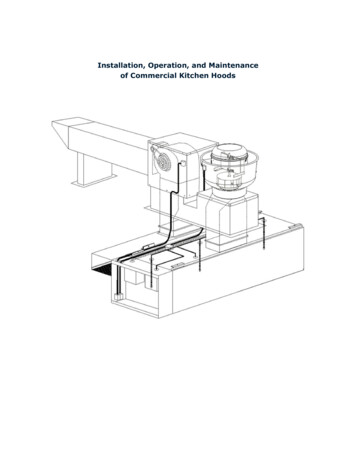
Parts SuppliedInstallation DimensionsFor information on ordering, see “Replacement Parts” section.NOTE: The grounded 3 prong outlet must be inside the uppercabinet. See “Electrical Requirements” section.GAAHD23⁷ ₈"(60.6 cm) min.*24¹ ₈"(61.2 cm) max.*I21" (53.3 cm) min.21⁵ ₈" (54.9 cm)**11¹⁵ ₁₆" (30.3 cm) min.13³ ₄" (34.9 cm) max.JBE39" (99.1 cm) min.KCLFA. L-brackets (2)B. Rear trimC. Bottom plateD. VisorE. Grease filterF. Damper assemblyMG. 16 mm wood screws (10)H. 9.5 mm metal screws (10)I. 16 mm round-head bolts (2)J. 17 mm shoulder screws (2)K. Washers (2)L. Hex keyM. Leveling screws (4)A. Grounded 3 prong outlet*Measure from the front edges of the side cabinets.**For installation with stainless steel filler panel.NOTE: To avoid stress on the power cord, a minimum of 1¹ ₂"(3.8 cm) must exist between the top surface of the microwaveoven’s upper component housing and the bottom of the uppercabinet.Product DimensionsLocation RequirementsCheck the opening where the microwave oven will be installed.The location must provide: Minimum installation dimensions. See “InstallationDimensions” illustration. Side cabinets: Support for weight of 75 lbs (34 kg) each,which includes microwave oven and items placed inside themicrowave oven and side cabinets. Grounded electrical outlet inside upper cabinet. See“Electrical Requirements” section.NOTES: Installation requires venting above the microwave oven. Recirculation installation requires venting through a kitchensoffit. See “Venting Requirements” section. A charcoal filterkit should be used for recirculation. See “Assistance” sectionfor information on ordering. If you are using a rectangular to round transition piece, 3"(7.6 cm) clearance needs to exist above the damperassembly so that the damper blade can open freely and fully.See “Rectangular to Round Transition” illustration in “VentingRequirements” section. Some cabinet and building materials are not designed towithstand the heat produced by the microwave oven forcooking. Check with your builder or cabinet supplier to makesure that the materials used will not discolor, delaminate orsustain other damages.11¹20⁷ ₁₆"(51.9 cm)³ ₁₆"12⁵ ₈"(3016¹ ₈"(40.9 cm).0 c(32m)m).8 c.0 cm)59₆" ( ₁23⁹3
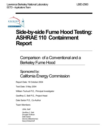
Electrical RequirementsWARNINGElectrical Shock HazardPlug into a grounded 3 prong outlet.Do not remove ground prong.Do not use an adapter.Do not use an extension cord.Failure to follow these instructions can result in death,fire, or electrical shock.Observe all governing codes and ordinances.Required: A 120 volt, 60 Hz, AC only, 15- or 20-amp electrical supplywith a fuse or circuit breaker.Recommended: A time-delay fuse or time-delay circuit breaker. A separate circuit serving only this microwave oven.GROUNDING INSTRUCTIONS Venting RequirementsThis section is intended for architectural designer andbuilder/contractor reference only.NOTES: If installing for recirculation, venting must be routed up andout through an exhaust register (not provided) in a kitchensoffit. A charcoal filter kit (not provided) should be used. See“Assistance” section for information on ordering. Vent materials needed for installation are not provided withmicrowave hood combination. We do not recommend using a flexible metal vent. To avoid possible product damage, be sure to vent airoutside, unless using recirculation installation. Do not ventexhaust air into concealed spaces, such as spaces withinwalls or ceilings, attics, crawl spaces or garages.For optimal venting installation, we recommend:using roof or wall caps that have back draft dampersusing a rigid metal vent using the most direct route by minimizing the length of thevent and number of elbows to provide efficient performance using uniformly sized vents using duct tape to seal all joints in the vent system using caulking compound to seal exterior wall or roof openingaround cap for optimal hood performance, do not install 2 elbowstogetherIf rectangular to round transition is used, be sure there is at least3" (7.6 cm) of clearance between the top of the damper assemblyand the transition piece. See “Rectangular to Round Transition”illustration. For all cord connected appliances:The microwave oven must be grounded. In the event ofan electrical short circuit, grounding reduces the risk ofelectric shock by providing an escape wire for the electriccurrent. The microwave oven is equipped with a cordhaving a grounding wire with a grounding plug. The plugmust be plugged into an outlet that is properly installedand grounded.WARNING: Improper use of the grounding plug canresult in a risk of electric shock. Consult a qualifiedelectrician or serviceman if the grounding instructions arenot completely understood, or if doubt exists as to whetherthe microwave oven is properly grounded.Recirculation ventingExhaust registerRoof ventingRoof capWall ventingWall capDo not use an extension cord. If the power supply cord istoo short, have a qualified electrician or serviceman installan outlet near the microwave oven.SAVE THESE INSTRUCTIONS4
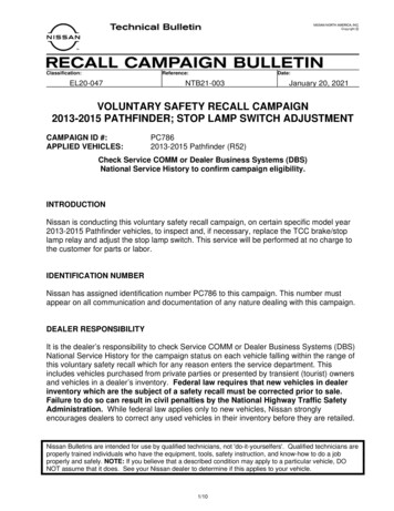
Rectangular to Round TransitionNOTE: The minimum 3" (7.6 cm) clearance must exist betweenthe top of the damper assembly and the rectangular to roundtransition piece so that the damper can open freely and fully.ABCDERecommended Vent LengthA 3¹ ₄" x 10" (8.3 x 25.4 cm) rectangular or 6" (15.2 cm) round ventshould be used.The total length of the vent system including straight vent,elbow(s), transitions and wall or roof caps must not exceed theequivalent of 140 ft (42.7 m) for either type of vent. See“Recommended Standard Fittings” section for equivalent lengths.For best performance, use no more than three 90 elbows.To calculate the length of the system you need, add the equivalentlengths of each vent piece used in the system. See the followingexamples:3¹ ₄" x 10" (8.3 x 25.4 cm) vent system 73 ft (22.2 m) totalF3" (7.6 cm)AB6 ft (1.8 m)A. Roof capB. 6" (15.2 cm) min. diameter round ventC. Elbow (for wall venting only)D. Wall capE. 3¹ ₄" x 10" to 6" (8.3 x 25.4 cm to 15.2 cm)rectangular to round transition pieceF. Vent extension piece, at least 3" (7.6 cm) highRecommended Standard FittingsThe following length equivalents are for use when figuring ventlength. See the examples in “Recommended Vent Length.”ABC2 ft(0.6 m)CA. One 3¹ ₄" x 10" (8.3 x 25.4 cm) 90 elbow 25 ft (7.6 m)B. 1 wall cap 40 ft (12.2 m)C. 2 ft (0.6 m) 6 ft (1.8 m) straight 8 ft (2.4 m)6" (15.2 cm) vent system 73 ft (22.2 m) totalAB6 ft (1.8 m)2 ft(0.6 m)CDEFGA. Rectangular to round transition piece: 3¹ ₄" x 10" to 6" 5 ft(8.3 x 25.4 cm to 15.2 cm 1.5 m)B. Roof cap: 3¹ ₄" x 10" 24 ft (8.3 x 25.4 cm 7.3 m)C. 90 elbow: 3¹ ₄" x 10" 25 ft (8.3 x 25.4 cm 7.6 m)D. 90 elbow: 6" 10 ft (15.2 cm 3 m)E. Wall cap: 3¹ ₄" x 10" 40 ft (8.3 x 25.4 cm 12.2 m)F. 45 elbow: 6" 5 ft (15.2 cm 1.5 m)G. 90 flat elbow: 3¹ ₄" x 10" 10 ft (8.3 x 25.4 cm 3 m)DA. Two 90 elbows 20 ft (6.1 m)B. 1 wall cap 40 ft (12.2 m)C. 1 rectangular to round transition piece 5 ft (1.5 m)D. 2 ft (0.6 m) 6 ft (1.8 m) straight 8 ft (2.4 m)If the existing vent is round, a rectangular to round transition piecemust be used. In addition, a rectangular 3" (7.6 cm) extension ventbetween the damper assembly and rectangular to round transitionpiece must be installed to keep the damper from sticking.5
INSTALLATION INSTRUCTIONSInstall L-Brackets1. Measure and mark a line on each of the side cabinets at least18¹ ₈" (46.0 cm) above the surface of the cooktop. See“Installation Dimensions” in the “Location Requirements”section.Make sure each line is level front to back, and that the linesare level to each other.4. Using 2 mm drill, drill holes marked in Step 3.5. Secure L-brackets to side cabinets with ten 16 mm woodscrews, 5 in each L-bracket.Prepare Upper Cabinet1. Find the centerline of the installation space. Mark thecenterline on the bottom of the upper cabinet.2. Measure and mark the power cord and vent holes, as shown,making sure they are centered on the centerline.B7" (17.8 cm)¹¹ ₁₆" (1.8 cm) min.Uppercabinetbottom7" (17.8 cm)Centerline5" (12.7 cm)A18¹ ₈" (46.0 cm) min.2¹ ₄"(5.7 cm)CRear wall3. Cut the power cord hole using the 1¹ ₂" (3.8 cm) hole drill bit.4. Cut 3/4" (19 mm) hole at one corner of the vent hole marking.5. Using a keyhole saw, cut out the rectangular vent area.A. Rear wallB. Side cabinetC. Cooktop surface2. Hold L-bracket against the side cabinet, with the bottom ofthe horizontal arm aligning with the line drawn in Step 1, andthe vertical arm against the rear wall.NOTES:If installing into frameless or flush face-frame cabinetry (nofront face or protruding trim), position each bracket so thatthe narrow arm is horizontal, and the wide arm is againstthe rear wall. If installing into face-frame cabinetry, position eachbracket so that the wide arm is horizontal, and the narrowarm is against the rear wall.3. Mark 3 holes through the horizontal arm onto the side cabinet,then mark 2 holes through the vertical arm onto the sidecabinet, 1 at the top and 1 at the bottom. Installation into frameless orflush face-frame cabinetry1¹ ₂" (3.8 cm)diam.Install Stainless Steel Panel Kit(optional steps)If you decide to cover the upper component housing with thestainless steel panel (not provided), you will need to order thestainless steel panel kit. See “Assistance” section for informationon ordering.The panel must be attached to the microwave oven beforeinstallation.1. Peel off adhesive strip covers on bottom edge of panel, andplace the panel on the top edge of the front facing of themicrowave oven.Installation into faceframe cabinetryCCABA. Bottom edge of stainless steel panelB. Top edge of microwave oven front facing2. Secure panel to upper component housing with 3 mountingscrews.ABA. Narrow armB. Wide armC. Mounting holes6
Install the Microwave Oven5. Place a washer on each 16 mm round-head bolt, then installeach bolt through the L-bracket base slot, into the mountinghole in the bottom of the microwave oven. Do not overtighten.1. Remove any contents of the microwave oven.WARNINGExcessive Weight HazardUse two or more people to move and installmicrowave oven.Failure to do so can result in back or other injury.2. Using 2 or more people, lift microwave oven, and place it ontothe L-brackets. Gently slide the microwave oven back againstthe rear wall.Install Damper Assembly1. Insert damper assembly through the upper cabinet cutout,and orient it so that the 3 mounting holes are toward the backof the microwave oven.A3. Check level of microwave oven.4. Start the leveling screws in the front and back holes of theL-bracket bases, and adjust the level using the hex key, ifnecessary.BCA. Damper assemblyB. Upper cabinet cutoutC. 9.5 mm metal screws (5)2. Secure the damper assembly to the upper componenthousing with five 9.5 mm metal screws.7
Install Bottom PlateNOTE: Pre-tap front mounting holes prior to bottom plateattachment. (See Step 2.)1. Hook the heads of the screws through the keyholes at theback of the microwave oven bottom, as shown, then slidebottom plate back.Install Rear Trim1. Measure the distance from the rear wall to the front edge ofthe rear frame of the bottom plate.ABDCA. Left side cabinet bottomB. Bottom plateC. Rear frame of bottom plateD. Rear wall2. Cut the rear trim to the same measurement.A2. Secure bottom plate onto microwave oven bottom using two9.5 mm metal screws through the front mounting holes.BA. Rear trimB. Adhesive cover3. Peel off adhesive strip covers, and place the rear trim againstthe rear wall and microwave oven bottom.NOTE: Make sure trim does not cover the opening for greasefilter.AA. Opening for grease filter4. Secure rear trim with three 9.5 mm metal screws.8
2. Insert wire rods to hold charcoal filter in place.Install Visor1. Open visor, and slide its mounting tray – with the mountingtray edges facing down – into the slot between the microwaveoven bottom and the bottom plate, as shown.AABCBA. Charcoal filterB. Grease filterC. Wire rodsC3. Install grease filter. See “Install Grease Filter” section.A. VisorB. Visor mounting trayC. Bottom plateInstall Grease Filter2. Secure visor by installing two 17 mm shoulder screws throughthe bottom plate into the visor mounting tray.1. Place bracket end of the grease filter into one side of thebottom plate opening, push toward the bracket end, andswing up the tabbed end of the grease filter.ACBABCA. VisorB. 17 mm shoulder screwsC. Bottom plateA. Grease filterB. TabsC. Bracket2. Push the tabbed end of the grease filter up until the tabs areabove the opening, then release the tension.Install Charcoal Filter Kit(for recirculation venting only)The charcoal filter kit should be used. See “Assistance” sectionfor information on ordering.To Install Charcoal Filter:1. Cover the inside of the grease filter with the charcoal filter.ABA. Charcoal filterB. Grease filter9
Complete Installation1. Connect all venting and ductwork necessary for the type ofinstallation (roof venting, wall venting or recirculation). See“Venting Requirements” section.2. Install turntable support and turntable.WARNINGNOTE: After installation is complete, the upper componenthousing on the top of the microwave oven will be visible (Figure 1).The housing may be covered using a stainless steel panel kit(Figure 1A). See “Assistance” section for information on ordering.The housing may also be covered using cabinet customization(Figure 1B). Check with your cabinet supplier/builder.Figure 1AElectrical Shock HazardPlug into a grounded 3 prong outlet.Do not remove ground prong.Do not use an adapter.Do not use an extension cord.Failure to follow these instructions can result in death,fire, or electrical shock.3. Plug microwave oven into grounded 3 prong outlet.4. Check the operation of microwave oven by placing 1 cup(250 mL) of water on the turntable, and programming a cooktime of 1 minute at 100% power. Test vent fan and exhaust byoperating the vent fan.5. If the microwave oven does not operate: Check that a household fuse has not blown, or that acircuit breaker has not tripped. Replace the fuse or resetthe circuit breaker. If the problem continues, call anelectrician. Check that the power supply cord is plugged into agrounded 3 prong outlet. See the Use and Care Guide for troubleshootinginformation.Figure 1ABInstallation is now complete.Save Installation Instructions for future use.Figure 1BAA. Upper component housingB. Stainless steel panel10
ASSISTANCECall your authorized dealer or service center. When you call, you will need the microwave oven model number and serial number. Bothnumbers can be found on the model and serial number plate, which is located behind the microwave oven door on the front frame ofthe microwave oven.If you need additional assistance, call us at our toll free number or visit our website listed in the Use and Care Guide.Replacement PartsIf any of the installation hardware needs to be replaced, call us atour toll free number listed in the Use and Care Guide.Following is a list of available replacement parts. You will needyour model number located on the front facing of the microwaveoven opening, behind the door. Damper Assembly Visor Rear Trim Mounting Screw Kit (includes parts G-M in “Parts Supplied” inthe “Tools and Parts” section) L-bracketsKitsThe following kits are not provided but may be ordered. Charcoal Filter Kit (Part Number W10610033) Includes:1 charcoal filter2 wire rods Stainless Steel Panel Kit (Part Number W11170104) Includes:1 stainless steel panel3 mounting screws1 Installation Instruction11
SÉCURITÉ DE L’ENSEMBLE FOUR À MICRO-ONDES/HOTTEVotre sécurité et celle des autres est très importante.Nous donnons de nombreux messages de sécurité importants dans ce manuel et sur votre appareil ménager. Assurez-vous detoujours lire tous les messages de sécurité et de vous y conformer.Voici le symbole d’alerte de sécurité.Ce symbole d’alerte de sécurité vous signale les dangers potentiels de décès et de blessures graves à vouset à d’autres.Tous les messages de sécurité suivront le symbole d’alerte de sécurité et le mot “DANGER” ou“AVERTISSEMENT”. Ces mots signifient :Risque possible de décès ou de blessure grave si vous nesuivez pas immédiatement les instructions.DANGERAVERTISSEMENTRisque possible de décès ou de blessure grave si vousne suivez pas les instructions.Tous les messages de sécurité vous diront quel est le danger potentiel et vous disent comment réduire le risque de blessure etce qui peut se produire en cas de non-respect des instructions.EXIGENCES D'INSTALLATIONOutils et piècesOutils nécessairesMatériaux nécessairesRassembler les outils et pièces nécessaires avant d’entreprendrel’installation. Lire et observer les instructions fournies avec chacundes outils de la liste ci-dessous. 12Mètre rubanCrayonCutterTournevis Phillips n 3PerceuseCloche à percer de 1¹ ₂"(3,8 cm) (pour bois) Foret 2 mmScie-cloche de 3/4"(19 mm)Scie à guichetRuban adhésif pourconduitNiveauRaccords standard pour évacuation. Voir la section“Exigences du circuit d'évacuation”.
Pièces fournies Pour la commande de pièces, voir la section “Pièces derechange”.GAHLes matériaux de certains placards et certains matériaux deconstruction peuvent ne pas résister à la chaleur émise par lefour à micro-ondes lors des opérations de cuisson. Consulterle constructeur de la maison ou le fabricant des placardspour déterminer si les matériaux utilisés pourraient subir unchangement de couleur, une déstratification ou d'autresdommages.Dimensions à respecter lors de l'installationREMARQUE : La prise de courant à 3 alvéoles reliée à la terre doitêtre située à l'intérieur du placard mural. Voir la section“Spécifications électriques”.DIAJBE23⁷ ₈"(60,6 cm) min.*24¹ ₈"(61,2 cm) max.*KC21" (53,3 cm) min.21⁵ ₈" (54,9 cm)**11¹⁵ ₁₆" (30,3 cm) min.13³ ₄" (34,9 cm) max.LFA. Supports en “L” (2)B. Garniture arrièreC. Plaque inférieureD. Écran mobileE. Filtre à graisseF. Clapet anti-retour39" (99,1 cm) min.MG. Vis en bois de 16 mm (10)H. Vis de tôlerie de 9,5 mm (10)I. Vis à tête ronde de 16 mm (2)J. Vis à épaulement de 17 mm (2)K. Rondelles (2)L. Clé à tête hexagonaleM. Vis de nivellement (4)Exigences d’emplacementInspecter l'ouverture où le four à micro-ondes sera installé. Il doitcomporter les caractéristiques suivantes : Dimensions minimales à respecter lors de l'installation. Voirl'illustration “Dimensions à respecter lors de l'installation”. Placards latéraux : Capables de supporter une charge de75 lb (34 kg) pour chaque placard - ceci comprend le four àmicro-ondes et les articles placés à l’intérieur du four àmicro-ondes et des placards latéraux. Prise de courant électrique reliée à la terre à l’intérieur duplacard mural. Voir la section “Spécifications électriques”.REMARQUES : Un système d'évacuation doit être installé au-dessus du fourà micro-ondes. Pour une installation sans décharge à l'extérieur (recyclage),l'évacuation doit se faire à travers un soffite dans la cuisine.Voir la section “Exigences du circuit d'évacuation”. Pour uneinstallation avec recyclage, on doit utiliser un ensemble defiltre à charbon. Voir la section “Assistance” pour connaître leprocessus de commande. Si l'on utilise un raccord de transition rectangulaire/rond, ondoit disposer d’un espace libre de 3" (7,6 cm) au-dessus duclapet anti-retour afin que la lame du clapet puissemanœuvrer complètement et librement. Voir l’illustration“Raccord de transition rectangulaire/rond” dans la section“Exigences du circuit d'évacuation”.A. Prise à 3 alvéoles reliée à la terre*Prendre les mesures à partir des rebords avant des placardslatéraux.**Pour une installation avec panneau de remplissage en acierinoxydable.REMARQUE : Afin d'éviter de créer une tension sur le cordond'alimentation, on doit laisser un dégagement minimal de 1¹ ₂"(3,8 cm) entre le haut du compartiment du composant supérieurdu four à micro-ondes et le bas du placard supérieur.Dimensions du produit11¹³ ₁₆"(3012⁵ ₈"16¹ ₈"(40,9 cm),0 c20⁷ ₁₆"(51,9 cm)(32m),0 cm)₆"3⁹ ₁m),8 c(59213
Spécifications électriquesAVERTISSEMENTRisque de choc électriqueBrancher sur une prise à 3 alvéoles reliée à la terre.Ne pas enlever la broche de liaison à la terre.Ne pas utiliser un adaptateur.Ne pas utiliser un câble de rallonge.Le non-respect de ces instructions peut causerun décès, un incendie ou un choc électrique.Observer les dispositions de tous les codes et règlements envigueur.Nécessaire : Une alimentation électrique de 120 volts, 60 Hz, CAseulement, 15 ou 20 ampères, protégée par un fusible ou undisjoncteur.Recommandé : Un fusible temporisé ou un disjoncteur temporisé. Un circuit distinct exclusif à ce four à micro-ondes.INSTRUCTIONS DE LIAISONÀ LA TERRE Pour tout appareil ménager connecté par un cordonde courant électrique :Il faut que le four à micro-ondes soit relié à la terre. Encas de court-circuit électrique, la liaison à la terre réduit lerisque de choc électrique car le courant électriquedispose d’un itinéraire direct d’acheminement à la terre.Le four à micro-ondes est doté d’un cordon de courantélectrique qui comporte un fil de liaison à la terre, avecbroche de liaison à la terre. On doit brancher la fiche surune prise de courant convenablement installée et reliée àla terre.AVERTISSEMENT : L’utilisation incorrecte dudispositif de liaison à la terre peut susciter un risque de chocélectrique. L’utilisateur qui ne comprend pas bien lesinstructions de liaison à la terre, ou qui n’est pas certain quele four à micro-ondes soit convenablement relié à la terre,devrait consulter un électricien ou un technicien qualifié.Exigences du circuit d'évacuationCette section présente de l'information de référence uniquement,à l'intention des architectes/concepteurs et constructeurs.REMARQUES : Pour une installation avec recyclage, les raccords deventilation doivent être acheminés jusqu'à (et à travers) unegrille d'évacuation (non fournie) dans un soffite de la cuisine.Utiliser un ensemble de filtre à charbon (non fourni). Voir lasection “Assistance” pour connaître le processus decommande. Les matériaux du circuit d'évacuation nécessaires àl’installation ne sont pas fournis avec l'ensemble four àmicro-ondes/hotte. On déconseille l'emploi d'un conduit métallique flexible. Pour éviter d'éventuelles détériorations du produit, veiller àce que l'air aspiré soit déchargé à l'extérieur (sauf dans le casd'une installation avec recyclage). Veiller à ce que l'air aspiréne soit pas déchargé dans un espace fermé dissimulé :cavités murales ou un plafond, grenier, vide sanitaire ougarage.Recommandations pour une installation optimale ducircuit d'évacuation :utiliser une bouche de décharge (murale ou sur toit)comportant un clapet anti-reflux à l’arrière utiliser un conduit métallique rigide utiliser l'itinéraire d'acheminement le plus direct; minimiser lalongueur du circuit et le nombre de coudes pour obtenir unfonctionnement efficace utiliser des conduits de taille uniforme assurer l'étanchéité de toutes les jointures du systèmed'évacuation avec du ruban adhésif pour conduits utiliser un composé de calfeutrage pour assurer l'étanchéitéautour de la bouche de décharge (murale ou sur toit) pour optimiser la performance de la hotte, ne pas connecterensemble 2 raccords coudésDans le cas d’une décharge à travers le toit, si on doit utiliser unraccord de transition (rectangulaire/rond), veiller à disposer d'unespace libre d'au moins 3"
4 Electrical Requirements Observe all governing codes and ordinances. Required: A 120 volt, 60 Hz, AC only, 15- or 20-amp electrical supply with a fuse or circuit breaker. Recommended: A time-delay fuse or time-delay circuit breaker. A separate circuit serving only this microwave oven. Venting Requirements