Transcription
VLT 6000 HVAC ContentsIntroduction to HVAC.Safety regulations .Warning against unintended start 5151516Programming18181819192022232324.Mechanical installation .IP 00 VLT 6400-6550 380-460 V .High voltage warning .Earthing .Cables .Screened/armoured cables .Extra protection with regard to indirect contact .RFI switch .High voltage test .Heat emission from VLT 6000 HVAC .Ventilation of integrated VLT 6000 HVAC .Electrical installation - earthing of control cables .Tightening-up torque and screw sizes .Mains connection .Pre-fuses .Motor connection .Direction of motor rotation .Motor cables .Motor thermal protection .Earth connection .DC bus connection .High-voltage relay .Control card .Connection examples, VLT 6000 HVAC .Control unit LCP .Control keys for parameter setup .Indicator lamps .Local control .Display mode .Navigation between display modes .Changing data .Manual initialisation .Quick Menu .All about VLT 6000 HVAC. 25Status messages . 25List of warnings and alarms . 27MG.60.C6.02 - VLT is a registered Danfoss trademark1
VLT 6000 HVACThe voltage of the frequency converteris dangerous whenever the equipmentis connected to mains. Incorrectinstallation of the motor or the frequency convertermay cause damage to the equipment, seriouspersonal injury or death.Consequently, the instructions in this manual,as well as national and local rules and safetyregulations, must be complied with.6. Do not remove the plugs for the motor and mainssupply while the frequency converter is connectedto mains. Check that the mains supply has beendisconnected and that the necessary time haspassed before removing motor and mains plugs.7. Reliable galvanic isolation (PELV) is not compliedwith if the RFI switch is placed in OFF position.This means that all control in - and outputscan only be considered low-voltage terminalswith basic galvanic isolation.8. Please note that the frequency converter hasmore voltage inputs than L1, L2 and L3, whenthe DC-bus terminals are used.Check that all voltage inputs have beendisconnected and that the necessary time haspassed before repair work is commenced. Safety regulations1. The frequency converter must be disconnectedfrom mains if repair work is to be carried out. Checkthat the mains supply has been disconnectedand that the necessary time has passed beforeremoving motor and mains plugs.2. The [OFF/STOP] key on the control panel ofthe frequency converter does not disconnectthe equipment from mains and is thus not to Warning against unintended start1. The motor can be brought to a stop bybe used as a safety switch.means of digital commands, bus commands,3. Correct protective earthing of the equipmentreferences or a local stop, while the frequencymust be established, the user must be protectedconverter is connected to mains.against supply voltage, and the motor must beIf personal safety considerations make it necessaryprotected against overload in accordance withto ensure that no unintended start occurs, theseapplicable national and local regulations.4. The earth leakage currents are higher than 3.5 mA.stop functions are not sufficient.5. Protection against motor overload is included in2. While parameters are being changed, thethe factory setting. Parameter 117, Motor thermalmotor may start. Consequently, the stop keyprotection default value is ETR trip 1.[OFF/STOP] must always be activated, followingNote: The function is initialised at 1.0 x ratedwhich data can be modified.motor current and rated motor frequency (see3. A motor that has been stopped may start if faultsparameter 117, Motor thermal protection).occur in the electronics of the frequency converter,or if a temporary overload or a fault in the supplymains or the motor connection ceases. Use on isolated mainsSee section RFI Switch regarding use on isolated mains.2MG.60.C6.02 - VLT is a registered Danfoss trademark
VLT 6000 HVACMG.60.C6.02 - VLT is a registered Danfoss trademarkIntroduction toHVACTouching the electrical parts may be fatal - even after the equipmenthas been disconnected from mains.Using VLT 6002-6005, 200-240 V:wait at least 4 minutesUsing VLT 6006-6062, 200-240 V:wait at least 15 minutesUsing VLT 6002-6005, 380-460 V:wait at least 4 minutesUsing VLT 6006-6072, 380-460 V:wait at least 15 minutesUsing VLT 6102-6352, 380-460 V:wait at least 20 minutesUsing VLT 6400-6550, 380-460 V:wait at least 15 minutesUsing VLT 6002-6006, 525-600 V:wait at least 4 minutesUsing VLT 6008-6027, 525-600 V:wait at least 15 minutesUsing VLT 6032-6275, 525-600 V:wait at least 30 minutes175HA490.11Warning:3
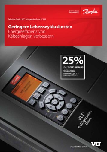
VLT 6000 HVAC Mechanical installation Installation of VLT 6002-6352Please pay attention to the requirementsAll frequency converters must be installed in athat apply to integration and field mountingway that ensures proper cooling.kit, see the below list. The information givenin the list must be observed to avoid serious damageCoolingor injury, especially when installing large units.The frequency converter must be installed vertically.The frequency converter is cooled by means of aircirculation. For the unit to be able to release its coolingair, the minimum distance over and below the unitmust be as shown in the illustration below.To protect the unit from overheating, it must beensured that the ambient temperature does not riseabove the max. temperature stated for the frequencyconverter and that the 24-hour average temperature isnot exceeded . The max. temperature and 24-houraverage can be seen from the General Technical Data.If the ambient temperature is in the range of 45 C -55 C, derating of the frequency converter will becomerelevant, see Derating for ambient temperature.The service life of the frequency converter willbe reduced if derating for ambient temperatureis not taken into account.4All Bookstyle and Compact units require a minimumspace above and below the enclosure.MG.60.C6.02 - VLT is a registered Danfoss trademark
VLT 6000 HVACSide by side/flange by flanged [mm]CommentsBookstyleVLT 6002-6005, 200-240 VVLT 6002-6011, 380-460 V100100Installation on a plane, vertical surface (no spacers)Compact (all enclosure types)VLT 6002-6005, 200-240 VVLT 6002-6011, 380-460 VVLT 6002-6011, 525-600 V100100100Installation on a plane, vertical surface (no spacers)VLTVLTVLTVLTVVVV200200225200Installation on a plane, vertical surface (no spacers)VLT 6042-6062, 200-240 VVLT 6100-6275, 525-600 V225225Installation on a plane, vertical surface (no spacers)VLT 6152-6352, 380-460 V225Installation on a plane, vertical surface (spacers can be used). IP 54 240380-460380-460525-600InstallationAll frequency converters can be mounted sideby side/flange by flange.IP 54 filter mats must be changed when they are dirty.mats must be changed when they are dirty.MG.60.C6.02 - VLT is a registered Danfoss trademark5
VLT 6000 HVAC Installation of VLT 6400-6550 380-460 V CompactIP 00, IP 20 and IP 54CoolingSide-by-sideAll units in the above-mentioned series require aminimum space of 400 mm above the enclosure andmust be installed on a plane floor. This applies toboth IP 00, IP 20 and IP 54 units.Gaining access to VLT 6400-6550 requires aminimum space of 605 mm in front of the frequencyconverter.All IP 00, IP 20 and IP 54 units in the above-mentionedseries can be installed side by side without any spacebetween them, since these units do not requirecooling on the sides. IP 00 VLT 6400-6550 380-460 VThe IP 00 unit is designed for installation in a cabinetwhen installed according to the instructions in the6VLT 6400-6550 Installation Guide MG.56.AX.YY.Please note, that the same conditions as for NEMA1/ IP20 and IP54 must be fulfilled.MG.60.C6.02 - VLT is a registered Danfoss trademark
VLT 6000 HVACthe cabinet rear plate, which must be made ofmetal, should be used as a common earth referenceplate. The metal cabinets of the different devicesare mounted on the cabinet rear plate using thelowest possible HF impedance. This avoids havingdifferent HF voltages for the individual devices andavoids the risk of radio interference currents runningin connection cables that may be used betweenthe devices. The radio interference will have beenreduced. In order to obtain a low HF impedance, usethe fastening bolts of the devices as HF connectionto the rear plate. It is necessary to remove insulatingpaint or similar from the fastening points.The voltage of the frequency converteris dangerous whenever the equipment isconnected to mains. Incorrect installationof the motor or the frequency converter may causedamage to the equipment, serious personal injuryor death. Consequently, the instructions in thisDesign Guide, as well as national and local safetyregulations, must be complied with. Touchingthe electrical parts may be fatal - even afterdisconnection from mains: Using VLT 6002-6005,200-240 V wait at least 4 minutesUsing VLT 6006-6062, 200-240 V wait atleast 15 minutesUsing VLT 6002-6005, 380-460 V wait at least 4 minutes CablesUsing VLT 6006-6072, 380-460 V wait atControl cables and the filtered mains cable shouldleast 15 minutesbe installed separate from the motor cables so as toUsing VLT 6102-6352, 380-460 V wait atavoid interference overcoupling. Normally, a distanceleast 20 minutesof 20 cm will be sufficient, but it is recommendedUsing VLT 6400-6550, 380-460 V wait atto keep the greatest possible distance whereverleast 15 minutespossible, especially where cables are installed inUsing VLT 6002-6006, 525-600 V wait at least 4 minutesparallel over a substantial distance.Using VLT 6008-6027, 525-600 V wait atWith respect to sensitive signal cables, such asleast 15 minutestelephone cables and data cables, the greatest possibleUsing VLT 6032-6275, 525-600 V wait atdistance is recommended with a minimum of 1 m per 5least 30 minutesm of power cable (mains and motor cable). It must bepointed out that the necessary distance depends onNB!:the sensitivity of the installation and the signal cables,It is the user’s or certified electrician’sand that therefore no precise values can be stated.responsibility to ensure correct earthing andIf cable jaws are used, sensitive signal cables are notprotection in accordance with applicableto be placed in the same cable jaws as the motornational and local norms and standards.cable or brake cable. If signal cables are to crosspower cables, this should be done at an angle of Earthing90 degrees. Remember that all interference-filledThe following basic issues need to be consideredin- or outgoing cables to/from a cabinet shouldwhen installing a frequency converter, so as to obtainbe screened/armoured or filtered.electromagnetic compatibility (EMC).See also EMC-correct electrical installation. Safety earthing: Please note that the frequencyconverter has a high leakage current and mustbe earthed appropriately for safety reasons.Apply local safety regulations.High-frequency earthing: Keep the earth wireconnections as short as possible.Connect the different earth systems at the lowestpossible conductor impedance. The lowest possibleconductor impedance is obtained by keeping theconductor as short as possible and by using thegreatest possible surface area. A flat conductor, forexample, has a lower HF impedance than a roundconductor for the same conductor cross-sectionCVESS. If more than one device is installed in cabinets,MG.60.C6.02 - VLT is a registered Danfoss trademark Screened/armoured cablesThe screen must be a low HF-impedance screen.This is ensured by using a braided screen ofcopper, aluminium or iron. Screen armour intendedfor mechanical protection, for example, is notsuitable for an EMC-correct installation. Seealso Use of EMC-correct cables. Extra protection with regard to indirect contactELCB relays, multiple protective earthing or earthing canbe used as extra protection, provided that local safety7Installation High voltage warning
VLT 6000 HVACregulations are complied with. In the case of an earthfault, a DC content may develop in the faulty current.Never use ELCB relays, type A, since such relaysare not suitable for DC fault currents.If ELCB relays are used, this must be: Suitable for protecting equipment with a directcurrent content (DC) in the faulty current(3-phase bridge rectifier) Suitable for power-up with short chargingcurrent to earth Suitable for a high leakage current8MG.60.C6.02 - VLT is a registered Danfoss trademark
VLT 6000 HVAC RFI switchMains supply isolated from earth:If the frequency converter is supplied from anisolated mains source ( IT mains), the RFI switch isrecommended to be turned off (OFF). In case optimumEMC performance is needed, parallel motors areconnected or the motor cable length is above 25 m, itis recommended to set the switch in ON position.In OFF position, the internal RFI capacities (filtercapacitors) between the chassis and the intermediatecircuit are cut off to avoid damage to the intermediatecircuit and to reduce the earth capacity currents(according to IEC 61800-3).Please also refer to the application note VLT onIT mains, MN.90.CX.02. It is important to useisolation monitors that are capable for use togetherwith power electronics (IEC 61557-8).Bookstyle IP 20VLT 6002 - 6011 380 - 460 VVLT 6002 - 6005 200 - 240 VInstallationNB!:The RFI switch is not to be operated withmains connected to the unit. Check thatthe mains supply has been disconnectedbefore operating the RFI switch.NB!:Open RFI switch is only allowed at factoryset switching frequencies.NB!:The RFI switch disconnects the capacitorsgalvanically to earth.The red switches are operated by means of e.g. ascrewdriver. They are set in the OFF position whenthey are pulled out and in ON position when theyare pushed in. Factory setting is ON.Compact IP 20 and NEMAVLT 6002 - 6011 380 - 460VLT 6002 - 6005 200 - 240VLT 6002 - 6011 525 - 6001VVVCompact IP 20 and NEMAVLT 6016 - 6027 380 - 460VLT 6006 - 6011 200 - 240VLT 6016 - 6027 525 - 6001VVVMains supply connected to earth:The RFI switch must be in ON position in order for thefrequency converter to comply with the EMC-standard.MG.60.C6.02 - VLT is a registered Danfoss trademark9
VLT 6000 HVACCompact IP 20 and NEMAVLT 6032 - 6042 380 - 460VLT 6016 - 6022 200 - 240VLT 6032 - 6042 525 - 6001VVVCompact IP 20 and NEMAVLT 6052 - 6122 380 - 460VLT 6027 - 6032 200 - 240VLT 6052 - 6072 525 - 6001VVVCompact IP 54VLT 6016 - 6032 380 - 460 VVLT 6006 - 6011 200 - 240 VCompact IP 54VLT 6102 - 6122 380 - 460 VCompact IP 54VLT 6042 - 6072 380 - 460 VVLT 6016 - 6032 200 - 240 V10Compact IP 54VLT 6002 - 6011 380 - 460 VVLT 6002 - 6005 200 - 240 VMG.60.C6.02 - VLT is a registered Danfoss trademark
VLT 6000 HVAC High voltage testA high voltage test can be carried out by short-circuitingterminals U, V, W, L1, L2 and L3 and energizingby max. 2.5 kV DC for one second betweenthis short-circuit and the chassis.NB!:The RFI switch must be closed (positionON) when high voltage tests are carried out.The mains and motor connection must beinterrupted in the case of high voltage tests of the totalinstallation if the leakage currents are too high.Installation Heat emission from VLT 6000 HVACThe tables in General technical data show thepower loss P (W) from VLT 6000 HVAC. Themaximum cooling air temperature tIN MAX, is 40 at 100% load (of rated value). Ventilation of integrated VLT 6000 HVACThe quantity of air required for cooling frequencyconverters can be calculated as follows:Add up the values of P for all the frequencyconverters to be integrated in the same panel.The highest cooling air temperature (t IN) presentmust be lower than tIN, MAX (40 C). The day/nightaverage must be 5 C lower (VDE 160). Theoutlet temperature of the cooling air must notexceed: tOUT, MAX (45 C).2. Calculate the permissible difference betweenthe temperature of the cooling air (tIN) andits outlet temperature (tOUT ):t 45 C-tIN.3. Calculate the requiredquantity of air m3/ht in Kelvininsert1.The outlet from the ventilation must be placed abovethe highest-mounted frequency converter. Allowancemust be made for the pressure loss across thefilters and for the fact that the pressure is goingto drop as the filters are choked.MG.60.C6.02 - VLT is a registered Danfoss trademark11
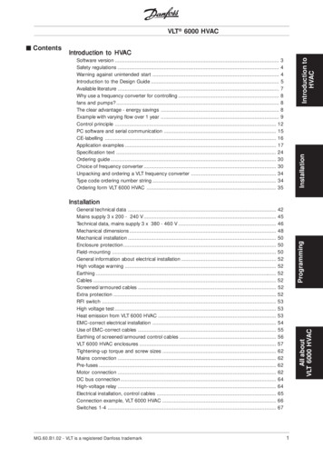
VLT 6000 HVAC Electrical installation - earthing of control cablesGenerally speaking, control cables must be braidedscreened/armoured and the screen must beconnected by means of a cable clamp at bothends to the metal cabinet of the unit.The drawing below indicates how correct earthing iscarried out and what to be done if in doubt.Correct earthingControl cables and cables for serial communicationmust be fitted with cable clamps at both ends toensure the best possible electrical contactWrong earthingDo not use twisted cable ends (pigtails), since theseincrease the screen impedance at high frequencies.Protection with respect to earth potentialbetween PLC and VLTIf the earth potential between the frequency converterand the PLC (etc.) is different, electric noise mayoccur that will disturb the whole system. Thisproblem can be solved by fitting an equalising cable,to be placed next to the control cable. Minimumcable cross-section: 16 mm 2.For 50/60 Hz earth loopsIf very long control cables are used, 50/60 Hz earthloops may occur. This problem can be solved byconnecting one end of the screen to earth via a100nF capacitor (keeping leads short).Cables for serial communicationLow-frequency noise currents between two frequencyconverters can be eliminated by connecting one end ofthe screen to terminal 61. This terminal is connectedto earth via an internal RC link. It is recommendedto use twisted-pair cables to reduce the differentialmode interference between the conductors.12MG.60.C6.02 - VLT is a registered Danfoss trademark
VLT 6000 HVAC Tightening-up torque and screw sizes Mains connectionThe table shows the torque required when fittingMains must be connected to terminals 91, 92, 93.terminals to the frequency converter. For VLTMains voltage 3 x 200-240 V6002-6032, 200-240 V, VLT 6002-6122, 380-460 and91, 92, 93Mains voltage 3 x 380-460 V525-600 V the cables must be fastened with screws.L1, L2, L3Mains voltage 3 x 525-600 VFor VLT 6042-6062, 200-240 V and for VLT 6152-6550,380-460 V, the cables must be fastened with bolts.NB!:These figures apply to the following terminals:Check that the mains voltage fits the mains91, 92, 93voltage of the frequency converter, whichMains terminals (Nos.)L1, L2, L3can be seen from the nameplate.Motor terminals (Nos.)96, 97, 98U, V, WEarth terminal (Nos.)94, 95, 99Tightening-upScrew/bolttorquesize3 x 200 - 240 VAllenkeysizeVLT 6002-60050.5-0.6 NmM3VLT 6006-60111.8 Nm (IP 20)M4VLT 6006-60161.8 Nm (IP 54)M4VLT 6016-60273.0 Nm (IP 20)M53)4 mmVLT 6022-602754)2)M53)4 mm5 mm3.0 Nm (IP Pre-fusesSee Technical data for correct sizing of pre-fuses.InstallationVLT typeSee Technical data for correct sizing of cablecross-sections. Motor connectionThe motor must be connected to terminals 96,97, 98. Earth to terminal 94/95/99.VLT 60326.0 NmM63)VLT 6042-606211.3 NmM8 (bolt)Tightening-upScrew/boltAllen96. 97. 98torquesizekeyU, V, WsizeNo. 94/95/99Nos.VLT type3 x 380-460 VVLT 6002-60110.5-0.6 NmM3VLT 6016-60271.8 Nm (IP 20)M4VLT 6016-60321.8 Nm (IP 54)M4VLT 6032-60523.0 Nm (IP 20)M53)4 mmVLT 6042-605254)2)M53)4 mm3.0 Nm (IPVLT 6062-60726.0 NmM63)5 mmVLT 6102-612215 Nm (IP 20)M83)6 mm24 Nm (IP 54)1)3)8 mmVLT 6152-635219 Nm4)M10 (bolt)VLT 6400-655042 NmM12 (bolt)Tightening-upScrew/bolttorquesizeVLT type3 x 525-600 VAllen0.5-0.6 NmEarth connectionSee Technical data for correct sizing of cablecross-sections.All types of three-phase asynchronous standard motorscan be used with a VLT 6000 HVAC unit.Small-size motors are normally star-connected.(220/380 V,/Y). Large-size motors aredelta-connected (380/660 V, /Y). The correctconnection and voltage can be read fromthe motor nameplate.keysizeVLT 6002-6011Motor voltage 0-100 % of mains voltageM3VLT 6016-60271.8 NmM4VLT 6032-60423.0 Nm2)M53)4 mmVLT 6052-60726.0 NmM63)5 mmVLT 6100-615011.3 NmM8VLT 6175-627511.3 NmM8NB!:In older motors without phase coilinsulation, a LC filter should be fitted tothe frequency converter output. See theDesign Guide or contact Danfoss.1. Loadsharing terminals 14 Nm/M6, 5 mm Allen key2. IP 54 units with RFI filter line terminals 6 Nm3. Allen screws (hexagon)4. Loadsharing terminals 9.5 Nm/M8 (bolt)MG.60.C6.02 - VLT is a registered Danfoss trademark13
VLT 6000 HVAC Direction of motor rotationProblems may arise at the start and at low rpm valuesif the motor sizes are widely different. This is becausethe relatively high ohmic resistance in small motorscalls for a higher voltage at the start and at low rpmvalues. In systems with motors connected in parallel,the electronic thermal relay (ETR) of the frequencyconverter cannot be used as motor protection forthe individual motor. Consequently, additional motorprotection is required, such as thermistors in eachmotor (or individual thermal relays).NB!:Parameter 107 Automatic Motor Adaptation,AMA and Automatic Energy Optimization, AEOin parameter 101 Torque characteristics cannotbe used if motors are connected in parallel.The factory setting is for clockwise rotation with thefrequency transformer output connected as follows.Terminal 96 connected to U-phaseTerminal 97 connected to V-phaseTerminal 98 connected to W-phaseThe direction of motor rotation can be changed byswitching two phases in the motor cable. Parallel coupling of motorsVLT 6000 HVAC is able to control several motorsconnected in parallel. If the motors are to have differentrpm values, the motors must have different ratedrpm values. Motor rpm is changed simultaneously,which means that the ratio between the ratedrpm values is maintained across the range. Thetotal current consumption of the motors is notto exceed the maximum rated output currentIVLT,N for the frequency converter.14 Motor cablesSee Technical data for correct sizing of motorcable cross-section and length.Always comply with national and local regulationson cable cross-sections.NB!:If an unscreened cable is used, someEMC requirements are not complied with,see EMC test results.If the EMC specifications regarding emission areto be complied with, the motor cable must bescreened, unless otherwise stated for the RFI filterin question. It is important to keep the motor cableas short as possible so as to reduce the noise leveland leakage currents to a minimum.The motor cable screen must be connected to themetal cabinet of the frequency converter and to themetal cabinet of the motor. The screen connectionsare to be made with the biggest possible surface (cableclamp). This is enabled by different installation devicesin the differentT frequency converters. Mounting withtwisted screen ends (pigtails) is to be avoided, sincethese spoil the screening effect at higher frequencies.If it is necessary to break the screen to install a motorisolator or motor contactor, the screen must becontinued at the lowest possible HF impedance.MG.60.C6.02 - VLT is a registered Danfoss trademark
VLT 6000 HVAC Motor thermal protectionThe electronic thermal relay in UL-approved frequencyconverters has received UL-approval for single motorprotection, as long as parameter 117 Motor thermalprotection has been set to ETR Trip and parameter 105Motor current IVLT,N, has been programmed for the ratedmotor current (can be read from the motor nameplate).Installation Earth connectionSince the leakage currents to earth may be higherthan 3.5 mA, the frequency converter must alwaysbe earthed in accordance with applicable na-tionaland local regulations. In order to ensure goodmechanical connection of the earth cable, its cablecross-section must be at least 10 mm2. For addedsecurity, an RCD (Residual Current Device) may beinstalled. This ensures that the frequency converterwill cut out if the leakage currents get too high.See RCD instructions MI.66.AX.02. DC bus connectionThe DC bus terminal is used for DC back-up,with the intermediate circuit being suppliedfrom an external DC source.Terminal nos.88, 89Contact Danfoss if you require further information. High-voltage relayThe cable for the high-voltage relay must be connectedto terminals 01, 02, 03. The high-voltage relay isprogrammed in parameter 323, Relay 1, out-put.No. 1Relay ouput 11 3 break, 1 2 makeMax 240 V AC, 2 AmpMin. 24 V DC 10 mA or24 V AC, 100 mAMax Cross-section:4 mm2/10 AWGTorque:0.5-0.6 NmScrew size:M3 Control cardAll terminals for the control cables are located underthe protective cover of the frequency converter. Theprotective cover (see drawing below) can be removedby means of a pointed object - a screwdriver or similar.MG.60.C6.02 - VLT is a registered Danfoss trademark15
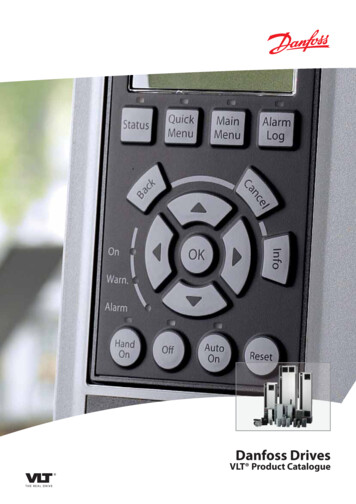
VLT 6000 HVAC Connection examples, VLT 6000 HVACThe diagram below gives an example of a typicalVLT 6000 HVAC installation.The mains supply is connected to terminals 91 (L1),92 (L2) and 93 (L3), while the motor is connected to96 (U), 97 (V) and 98 (W). These numbers can also beseen from the terminals of the frequency converter.An external DC supply or a 12-pulse option canbe connected to terminals 88 and 89. Please askDanfoss for a Design Guide to learn more.Analogue inputs can be connected to terminals 53 [V],54 [V] and 60 [mA]. These inputs can be programmedfor either reference, feedback or thermistor. SeeAnalogue inputs in parameter group 300.16There are 8 digital inputs, which can be connectedto terminals 16-19, 27, 29, 32, 33. These inputscan be programmed in accordance with the tablein Inputs and outputs 300-328.There are two analogue/digital outputs (terminals42 and 45), which can be programmed to showthe present status or a process value, such as0-fMAX. Relay outputs 1 and 2 can be used forgiving the present status or a warning.On terminals 68 (P ) and 69 (N-) RS 485 interface,the frequency converter can be controlled andmonitored via serial communication.MG.60.C6.02 - VLT is a registered Danfoss trademark
VLT 6000 HVAC Electrical installation, control cablesMax. control cable cross section: 1.5 mm 2 /16 AWGTorque: 0.5-0.6 NmScrew size: M3See Earthing of screened/armoured control cablesfor correct termination of control cables.No.Funct
VLT 6000 HVAC Introduction to HVAC Warning: 175HA490.11 Touching the electrical parts may be fatal - even after the equipment has been disconnected from mains. Using VLT 6002-6005, 200-240 V: wait at least 4 minutes Using VLT 6006-6062, 200-240 V: wait at least 15 minutes Using VLT 6002-6005, 380-460 V: wait at least 4 minutes