Transcription
Lightolier Controls is a registered trademark of Genlyte Thomas Group LLC.Lytemode and LyteScene are trademarks of Genlyte Thomas Group LLC.Lightolier ControlsA Genlyte Company10911 Petal StreetDallas, TX 75238214-647-7880Fax: 214-647-8032www.lolcontrols.comThis manual is for informational use only and is subject to change without notice.Lightolier Controls assumes no responsibility or liability for any claims resultingfrom errors or inaccuracies that may appear in this manual.Version as of: December 2005Document: 85-1463Lytemode 6-Button Remote Station User’s Guide 2005 Genlyte Group LLC. All Rights Reserved.
Table of ContentsCustomer Service .2Lytemode System Overview .3Quick Start .46-Button Remote Station Overview .5Installation .6Setting ILS Network ID .7Basic Setup .9Mode .9ID Address . 11IR Address .13LED Intensity .13Display Version .14Operation .15Selecting a Scene .15Changing Channel Levels .16Remote Keypad Functions .16Factory Defaults and Troubleshooting .17Resetting Factory Defaults .17Troubleshooting .18Installing Custom Buttons .19Specifications .20Accessories .206-Button Remote Station User’s Guide1
Customer ServiceTechnical and Sales assistance for Lytemode products areavailable worldwide.Phone: 1-800-526-2731 (In the United States and Canada) 1-214-647-7880 (Worldwide)2Customer Service
Lytemode System OverviewThe Lytemode System is designed to control architecturallighting by distributing both power and intelligence. The systemprovides processing power and control at each respective Master orRemote Station, eliminating the need for a central processor.Lytemode Master Stations provide individual control for up to 16channels, 13 scenes plus “Off”, and adjustable fade times. MultipleMaster Stations may be linked together for control of up to 128Channels and 13 preset scenes. By combining Lytemode MasterStations with Lytemode Remote Stations, the system providesremote access to scenes, Master Raise/Lower control, Multi-roompartition control, or Master Station Lockout. Lytemode MasterStations are easily programmed using the front panel buttons,without removing the Master Station from the wall, and without theneed for a computer. Lytemode Master Stations are compatible withboth Lightolier Controls Insulated Gate Bipolar Transistor(IGBT) Dimming Cabinets as well as Silicon Controlled Rectifier(SCR) Dimming Panels.Lytemode products are controlled by the Intelligent LytemodeSystem (ILS) protocol. All Lytemode control devices must beconnected to the ILS system and given a unique ID (or address) inorder to interact properly. The ID identifies the device on thenetwork and allows the device to avoid network collisions whentransmitting data.6-Button Remote Station User’s Guide3
Quick StartTo get the 6-Button Remote Station up and running quickly, use thefollowing checklist:Step 1. Install unit (refer to “Installation” on page 6).Step 2. Connect to Lytemode ILS Network (refer to “Setting ILSNetwork ID” on page 7).Step 3. Set the mode (refer to “Mode” on page 9).The unit should now be ready for operation.Notes:4 If the unit was set up as a Remote, then a Lytemode Mastermust be set to the same ID for the unit to function properly. If the unit was set up as a Global Remote, then a LytemodeMaster must be set up to allow Global Remotes - matchingthe unit’s ID - in order function properly.Quick Start
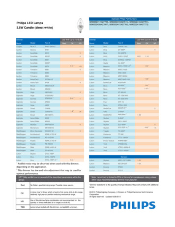
6-Button Remote Station OverviewThe Lytemode 6-Button Remote Station (ILS-CL-6RES) can beused to trigger Scenes and perform Master Raise/Lower, or act as aremote keypad for any specified ILS Master Station. It can beprogrammed to control multiple Master Stations, if required.The following diagram provides an overview of the 6-ButtonRemote Station controls:All Raise/Lower Buttons - Pressing will increase or decreaseall channel levels, respectively. This can be done at any timeand will not affect the stored levels.InfraRed Receiver Allows control byhandheld remote.*ONABON Button - PressingON will fade lights tothe stored preset level.CDOFF Button Pressing OFFfades lights out.OFFA, B, C and D Scenes Pressing any Scenebutton will fade lights tothe stored preset level.Note: Channel levels and fade rates for ON,OFF and Scenes A-D are stored at thecorresponding ILS Master Station.* Optional CLMIRTES Infra-Red Handheld Remote sold separately.6-Button Remote Station User’s Guide5
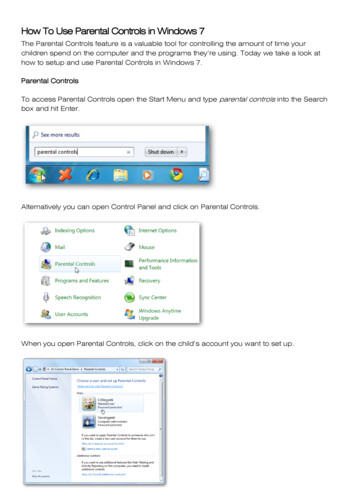
InstallationThe Lytemode ILS Network consists of a single CAT5e cableconnecting all ILS modules in a daisy chain manner. All unitsconnect to the network using a 9-pin connector (included).To install:Step 1. Unpack unit and inspect for any signs of shipping damage.Ensure that two mounting screws are included.Step 2. Connect ILS Network Cable to 9-pin connector at back of6-Button Remote Station.9-Pin Connector Wiring6-ButtonRemote Station9-PinConnectorRough-In Box(not included)PIN123456789SIGNALWH/OR ( Data)OR (- Data)SHIELDWH/GN ( Volts)GN (Ground)WH/BL ( Volts)BL (Ground)WH/BR ( Volts)BR (Ground)FaceplateStep 3. Insert 6-Button Station into standard deep rough-in box(not included). Secure with two supplied mounting screws.Step 4. Snap faceplate into place.6Installation
Setting ILS Network IDLytemode products are controlled by the Intelligent LytemodeSystem (ILS) protocol. All Lytemode ILS devices must be given anID (or address), which identifies the device on the network andallows it to avoid network collisions when transmitting data.Standard IDs are in the range of 1 to 255. An ID of 0 will disablethe unit and prevent it from transmitting on the network.IDs are typically unique. For example, an ILS Master will require aunique ID to allow dimmers to track its channel levels. However,ILS Remotes should be given the same ID as the ILS Master itcontrols. ILS Remotes rely on the fact that they are manuallytriggered to avoid network collisions with other ILS Remoteshaving the same ID.The table on the following page provides guidelines for addressing.6-Button Remote Station User’s Guide7
ILS Network Addressing:DeviceIDSub-IDDevices / IDRemotelyPolled?Notes *Remote1-2550MultipleNo1Two ButtonRemoteAuto0n/aNo4Global Remote1-2550MultipleNo2Remote Keypad1-2550-71Yes3Remote I/O1-2550-71Yes3Room 2550-71Yes3RS-232 PortAuto0n/aNo4Smart MatrixDimmer Rack1-255n/a1Yes3Capio DimmerRack1 -255n/a1Yes3* Notes:1 – Matches ILS Master ID.2 – ILS Masters must be programmed to accept.3 – Will respond to Remote Polls, Status Requests and Commands.4 – Unit uses a self generated ID.Note: Refer to the instructions included with your particulardevice(s) in order to set corresponding control IDs.8Setting ILS Network ID
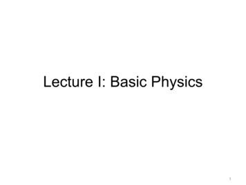
Basic SetupThis section describes how to program the unit’s Mode, Address, IRAddress, LED Brightness, and display the unit’s Software Version.ModeThe unit can be set to function in one of several Modes as follows:StepONABCDOFF1. Press and hold B and C for 3 or moreseconds. (ON LED will blink rapidly.)Step 2. Enter Mode by setting C, D and OFFbuttons as either Off or On as shown in thefollowing table. (LEDs will blink for anyMode not supported.)ModeCD0 – RemoteOffOffOffB1 – Global RemoteOffOffOnC2 – Remote KeypadOffOnOffD3 – Remote I/OOffOnOnONExample:Mode 3AOFFOFFStep 3. Press ON to save and exit.ONABC6-Button Remote Station User’s Guide9
ModeFunction0 – RemoteUsed to trigger Scenes and performMaster Raise/Lower on ILS Masters.1 – Global RemoteSame as Remote, but transmits a Globalcommand used to link several ILSMasters. ILS Masters must beprogrammed to respond to the Global ID.2 – Remote KeypadTransmits key presses and releases.LEDs are controlled by RemoteCommands.3 – Remote I/OControls a connected I/O module.10Basic Setup
ID AddressBecause there are not enough buttons/LEDs to address the full 0255 ID range, the ID must be entered in two stages. The three mostsignificant ID bits are entered first, followed by the five leastsignificant ID bits.ONABCDOFFONABCDOFFStep 1. Press and hold A and D for 3 or moreseconds. (ON LED will blink On 75% andOff 25%.)Step 2. Enter three most significant ID bits in CD-OFF. Use Raise/Lower to increment/decrement value.Step 3. Press ON. (ON LED will blink On 25%and Off 75%.)Step 4. Enter five least significant ID bits in A-BC-D-OFF. Use Raise/Lower toincrement/decrement value.Step 5. Press ON to save and exit.ID Values:ONABCDOFFC 128 (most significant ID)D 64 (most significant ID)OFF 32 (most significant ID)A 16 (least significant ID)B 8 (least significant ID)C 4 (least significant ID)D 2 (least significant ID)OFF 1 (least significant ID)6-Button Remote Station User’s Guide11
While in the Addressing Mode, the device will transmit a NetworkTest Command every 2 seconds (ON will blink). All devices on thenetwork will blink an LED to indicate their reception of thiscommand. If a receiving device matches the transmitted ID, it willblink all of its LEDs. Those devices that are capable of being polledwill return a Network Test Response if the transmitted ID matchestheir own ID. If the transmitting device sees a Network TestResponse, it will double blink its ON LED. This is useful fornetwork testing and to determine if the ID is unique.Note: When programming the ID of a unit set to Remote (Mode 0),tapping the Raise or Lower button on a Master, Mini-Master, oranother Remote unit will capture the ID and exit the Set ID mode.12Basic Setup
IR AddressThe IR Room select can be set as follows:ONABCDOFFONAStep 1. Press and hold A and C for 3 or moreseconds. A-B-C-D-OFF LEDs will turnOn. (Blinking LED shows presentlyselected room.)Step 2. Set IR Room as follows:A Room 1, B Room 2C Room 3, D Room 4OFF Disable IRStep 3. Press ON to save and exit.BLED IntensityThe intensity (brightness) of the LEDs can be set as follows:ONABCDOFFStep 1. Press and hold B and D for 3 or moreseconds. A-B-C-D LEDs will display fourintensity choices. (Current intensity settingbutton will blink.)Step 2. Press desired intensity button.Step 3. Press ON to save and exit.ON6-Button Remote Station User’s Guide13
Display VersionThe software version can be displayed as follows:ONABCDOFFStep 1. Press and hold D and OFF for 3 or moreseconds.The Version is displayed in binary formaton A-OFF.Step 2. Add up values for each illuminated LEDand then add 1.00.6-Button LEDValueABCDOFF.16.08.04.02.01Example:LEDs C and OFF are On, therefore .04 .01 1.00 Version 1.0514Basic Setup
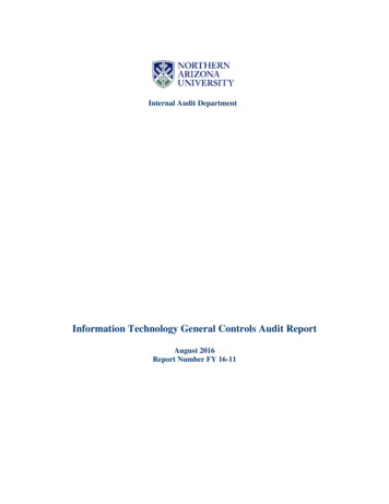
OperationSelecting a SceneA 6-button keypad can select all 14 Scenes (OFF, ON, A-L) bypressing a single button or a button combination as follows: To select Scenes OFF, ON, or A-D, press desired button. To select Scenes E-F-G-H, press ON and A-B-C-D. To select Scenes I-J-K-L, press OFF and A-B-C-D.For Scenes E-L, two LEDs will illuminate dimly for the patterns.OFF, ON, A-D Scenes:press desired button.I-J-K-L Scenes: pressOFF, plus desired button.E-F-G-H Scenes: pressON, plus desired FF6-Button Remote Station User’s Guide15
Changing Channel LevelsThe 6-Button Remote Station can perform Master Raise/Lowerfunctions. Pressing Raise or Lower will increase or decrease allchannel levels, respectively. This can be done at any time and willnot affect the stored levels.To change channel levels:ONABCStep 1. Select any Scene (ON, A-L). Refer to“Selecting a Scene” on page 15.Step 2. Press Raise to increase channel levels orLower to decrease channel levels.DOFFRemote Keypad FunctionsWhen set in Mode 2 (see “Mode” on page 9), the 6-Button RemoteStation will transmit key presses and releases to an ILS MasterStation. In this configuration, the LEDs are controlled by RemoteCommands. For key press instructions, refer to the User’s Guidewhich came with your Master Station unit.16Operation
Factory Defaults and TroubleshootingResetting Factory DefaultsTo set the unit back to its Factory Defaults, do the following:ONABCDOFFONABCDStep 1. Press and hold ON and OFF for 3 or moreseconds. (All LEDs will start to blink.)Step 2. While still holding ON/OFF buttons, alsopress and hold A. (After another 3seconds, unit will reset back to its FactoryDefaults.)Factory Defaults are as follows: Unit Mode 0 (Remote) Unit ID 0 (Disabled) LED intensity 75% IR DisabledOFF6-Button Remote Station User’s Guide17
TroubleshootingIn order to determine if all Lytemode ILS Network devices arecommunicating, a network test signal can be sent by placing thedevice in the Addressing Mode. While in this mode, the device willtransmit a Network Test Command every 2 seconds (ON willblink). All devices on the network will blink an LED to indicatetheir reception of this command. If a receiving device matches thetransmitted ID, it will blink all of its LEDs. Those devices that arecapable of being polled will return a Network Test Response if thetransmitted ID matches their own ID. If the transmitting device seesa Network Test Response, it will double blink its ON LED.ONABCTo send Network Test Command:Step 1. Press and hold A and D for 3 or moreseconds. Network will send out test signal.Step 2. Press ON to return to normal operation.DOFFONABCDOFF18Factory Defaults and Troubleshooting
Installing Custom ButtonsCustom engraved buttons* are available for Lytemode products.If you received custom buttons with your unit or obtain them in thefuture, use the following procedure for installation.To install custom buttons:Step 1. At 6-button unit, remove faceplate.Step 2. Remove 6-button plate by removing two screws.Step 3. Remove existing button pad.Step 4. Insert custom button pad and re-assemble components.PC BoardButton Pad6-Button PlateScrew (4)6-Button UnitFaceplate* Available from Lightolier Controls: www.lolcontrols.com6-Button Remote Station User’s Guide19
SpecificationsElectrical: Input Power: 18-26 VDC (powered from Lytemode ILS network) Current: 20mA Temperature- Storage: -25 to 85 C- Operating: 0 to 40 C- Relative Humidity: 30-90% (non-condensing)AccessoriesPart NumberDescriptionILSCK6B *Color Kit for 6-Button Remote StationCE6BES***Custom Engraved 6-Button Keypad MembraneCOMFP1 **Compli Screwless Faceplate, 1-GangCOMFP1CE ***Custom Engraved, Compli Screwless Faceplate, 1-GangLB-1G1-Gang Locking Security CoverCLMIRTESInfra-Red Handheld Remote*Color Kits available in: AL Almond, LA Light Almond, I Ivory, BR Brown,GR Gray, and BL Black**Faceplates available in: W White, AL Almond, LA Light Almond, I Ivory,BR Brown, GR Gray, and BL Black*** To order custom engraved keypads and faceplates, please visit our website at:www.lolcontrols.com20Specifications
3 YEAR LIMITED WARRANTYLightolier Controls warrants that this product will be free from defects in workmanship ormaterials. This warranty is void on any electronic controls which have been overloaded,abused, improperly installed or altered in any manner.Lightolier Controls’ sole obligation will be at its option to repair or replace any electroniccontrols product proven defective if it is returned, postage prepaid, to Lightolier Controls,10911 Petal St. Dallas, Texas 75238. Lightolier Controls will not pay for any charge-back orcharge for labor or material that does not have its prior written approval.This warranty shall be in lieu of any other warranty, express or implied, including but notlimited to any implied warranty of merchantability or fitness for a particular purpose. Somestates do not allow limitations on how long an implied warranty lasts and do not allow theexclusion or limitation of incidental or consequential damages, so the above limitation orexclusions may not apply to you. This warranty gives you specific legal rights, and you mayalso have other rights, which vary from state to state.Certain products illustrated in this manual are protected by applicable patents and patentspending. Lightolier Controls will aggressively defend all of its intellectual property. Thisproduct may be covered by one or more of the following U.S. Patents: #4,413,211;4,430,576; 4,465,956; 4,733,138; 4,792,731; 4,880,950; 4,988,840; 4,992,709; 5,004,969;5,004,969; 5,128,654; 5,153,816; 5,189,259; 5,194,858; 5,239,255; 5,239,255; 5,371,439;5,371,444; 5,506,480; 5,636,111; 5,642,104; 5,646,490; 5,814,550; 5,821,704; 5,920,156;5,930,126; Des. #307,578; 333,124; 435,203; 440,207; License #4482844; 5,004,969;5,239,255; and corresponding foreign patents. Other Utility, Design and Foreign PatentsPending.We reserve the right to change details of design, materials and finish in any way that will notalter the installed appearance or reduce function performance. Specifications are subject tochange without notice.
Lightolier Controls A Genlyte Company 10911 Petal Street Dallas, TX 75238 214-647-7880 Fax: 214-647-8032 www.lolcontrols.com This manual is for informational use only and is subject to change without notice. Lightolier Controls assumes no responsibility or liability for any claims resulting from errors or inaccuracies that may appear in this .