Transcription
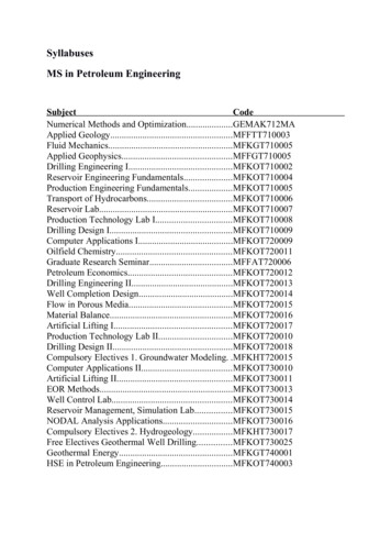
Installation Manual5755E00DAscent Toilet Pumping SystemModelsASC-1Macerator Unit, 115V,1 phase, AutomaticASC-2Toilet TankASC-3Toilet BowlContents1.) General InformationIMPORTANT:2.) IntroductionPrior to installation, record Model, Serial Number, andCode Number from pump nameplate for future reference.3.) InstallationMODELSERIAL4.) OperationCODE5.) Troubleshooting Chart6.) Parts DiagramINSTALLATIONDATE7.) Warranty7000 Apple Tree AvenueBergen, NY 14416Phone: (800) 543-2550Fax: (585) 494-1839www.libertypumps.com Copyright 2008 Liberty Pumps Inc. All rights reserved
1. General InformationBefore installation, read the following instructions carefully. Each Liberty pump is individually factory tested to insure properperformance. Closely following these instructions will eliminate potential operating problems, assuring years of trouble-free service. Risk of electric shock. Always disconnect the pump from the power source before handling or making adjustments.These pumps are not to be installed in locations classified as hazardous in accordance with the National Electric Code,ANSI/NFPA 70.The electrical connections and wiring for a pump installation should only be made by qualified personnel. This pump is supplied with a grounding conductor or a grounding-type attachment plug. To reduce the risk of electric shock, becertain that the grounding conductor is connected only to a properly grounded control panel or, if equipped with a grounding-typeplug, that it is connected to a properly grounded, grounding-type receptacle. Do not bypass grounding wires or remove ground prong from attachment plugs.Do not remove cord and strain relief, and do not connect conduit to pump.Do not use an extension cord.The installation must be in accordance with the National Electric Code and all applicable local codes and ordinances. Do not use these pumps in water over 120 F.Do not lift macerating tank by the power cord. Use the hand grip overhang on the cover.1-1INSPECTION UPON RECEIPT.The Ascent is shipped in 3 separate packages, the toilet tank (model ASC-2), toilet bowl (model ASC-3) and macerating unit(model ASC-1). The shipping containers should be immediately inspected for damage that may have occurred in shipment.Exercise care in opening the shipping container to avoid damage to the contents. Remove any blocking and cushioning fromwithin the containers.Check all cushioning for spare parts before discarding. Visually check the pump and any spare parts for damage. Check fordamaged electrical wires, especially where they exit the macerating tank. Report any damage or shortage of parts. This willinsure that the impeller and cutter is free of any seizure due to prolonged storage.1-2STORAGE BEFORE USELiberty pumps are shipped from the factory ready for installation and use. If storage is necessary, the pump should remain inits shipping container. It should be stored in a warehouse or storage shed that has a clean, dry temperature-stable area wherethe pump and its container should be covered to protect it from water, dirt, dust, etc. The ends of the cables - (plugs) must beprotected against moisture.1-3IMPORTANT. Do not allow the pump to freeze. If the home is allowed to freeze during winter months, ensure the maceratingunit and toilet is evacuated of water before closing the home. The tanks should be filled with plumber’s anti-freeze to protectagainst freezing conditions.2. Introduction2-1The macerating system can simultaneously receive wastewater from several sanitary fixtures, e.g. bidet, sink, shower,bathtub, or urinal, but only one water closet per unit.2-2Macerating systems are designed for the disposal of human waste, toilet paper and water. They are not intended to replacekitchen waste, neither are they intended to be used for the disposal of waste water from such pumped appliances asdishwashers and clothes washers.2-3Sanitary fixtures connected to the macerating system must be located on the same level. Copyright 2008 Liberty Pumps Inc.All rights reserved.2
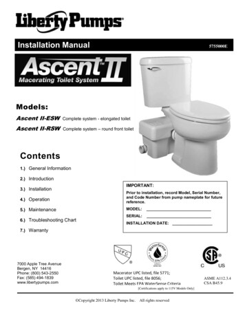
2-4The macerating system is a residential pumping system for toilet and bathroom fixtures. The macerator pump unit connects tothe outlet of a rear discharge toilet. The system is comprised of three major components: the macerator unit, the toilet bowland the toilet tank.2-5The macerator unit also consists of three major parts: the container which houses the operating mechanism; a pressurechamber which automatically activates and deactivates; the induction motor which drives the cutter blade and the impeller.2-6SANITARY INLETS: The macerating pump unit is equipped with two additional 1-1/2” inlets, one on either side of the case.These inlets, which incorporate an internal check valve, are used to connect the drainpipe of other sanitary fixtures to themacerating pump unit. Note: in case none of the inlets are used by other fixtures, you will need to block off the inlet with theplugs provided.2-7BATHTUBS AND SHOWER STALLS: Any regular bathtub or shower kit can be used. When installing these fixtures, oneshould build an 8” high platform, on which the fixture is placed. This gives enough space for a p-trap and slope toward thewastewater inlets. When installing a shower, manufacturers sometimes offer a pre-fabricated raised shower base. NOTE: Theactual distance between the p-trap of the additional fixture and macerating pump determines the necessary clearance to installthe p-trap and elevation required to ensure a minimum pitch of ¼” per foot.2-8NORMAL OPERATING CYCLE: As the flush is operated or as the bath, shower, or lavatory discharges, the water and wastematter enter the unit and the water level begins to rise, triggering the micro-switch in the pressure chamber. For safety themacerating unit should never be activated with the lid removed.3. InstallationNOTE: All installations should be done in accordance with federal, state and local codes. It is recommended that a certified orqualified installer perform these operations.3-1PREPARING THE MACERATING PUMP UNIT FOR INSTALLATION3-23-1-1Push the flapper check / elbow assembly into the discharge grommet on the tank lid. Orient the elbow as you wishand secure with a provided hose clamp.3-1-2Install the adapter grommet to the discharge elbow with a hose clamp. This adapter allows for either ¾” or 1”schedule 40 PVC discharge pipe to be connected to the system.3-1-3Install a rubber 1-1/2” grommet to the vent cylinder on the tank lid. Secure with a hose clamp. This grommet allowsfor 1-1/2” schedule 40 PVC vent pipe to be connected to the system.3-1-4If other fixtures are to be installed, install the appropriate 1-1/2” rubber grommets with hose clamps to the side(s) ofthe tank. Remove the ¼ turn plug before installation of the grommet. Included with the system is one 1-1/2” x 2”adapter for installations with 2” schedule 40 piping.SYSTEM ASSEMBLYSchematics: Typical Installation Diagrams. Refer to these diagrams when needed during the assembly process.Installations may vary per local plumbing and electrical codes. Also, discharge and vent pipe routing can vary perinstallation.Typical 2x4 construction wallVent piping,typicallybehind wallTo fixture:¼” per footslopeminimumSide View Copyright 2008 Liberty Pumps Inc.Front ViewAll rights reserved.Discharge piping,typically behindwallTo fixture:¼” per footslopeminimum3
3-33-43-53-2-1Place the macerating pump unit in the desired location and connect all inlet and outlet waste piping to the unit. Thenon-inlet side of the tank should be up against the wall to ensure proper toilet placement.3-2-2Assemble the toilet in accordance to the installation manuals provided with it.3-2-3Place the toilet in front of the macerating tank and slide the accordion style flapper over the discharge port on thetoilet. Do not install a hose clamp yet. Position the toilet such that the toilet tank is about 1 inch from the wall. Markthe floor through the two holes in the toilet bowl.3-2-4Remove toilet and bore two holes approximately 2-1/4” deep with a 5/16” masonry drill bit. Insert plastic plugs intoholes. If the floor is wood, bore a pilot hole with a ¼” drill bit.3-2-5Place the toilet over the holes in the floor. Slip the plastic china protectors over the lag screws. Tighten lag screws (donot over tighten) and snap plastic cover caps in place. Connect the accordion style grommet on the macerating tankto the toilet using a hose clamp to secure it.3-2-6Connect the toilet to the fill valve using a water supply hose.CONNECTION TO THE DISCHARGE PIPE WORK3-3-1The macerating unit has a “step-down” coupler. Simply cut off the appropriate portion of the coupler in order to fit it tothe discharge pipe. Use ridged wall pipe, not flexible pipe or hose, as flexible pipe may distort over time. ¾” or 1” pipemay be used.3-3-2Install a “full-port” ball or gate valve and a union in the discharge pipe in order to facilitate the removal of themacerating pump unit. Place the union or hose connector then the valve at the lower portion of the discharge pipe.CONNECTION TO THE SOIL-STACK OR SEWER3-4-1The macerating system will pump up to 15 feet, with a ¼” per foot gravity fall (minimum) constantly throughout thehorizontal run to the point of discharge. If you require a vertical lift it should precede any “horizontal” run and shouldcommence as near as possible to the discharge elbow. Once you have started the horizontal run, you may notchange directions in a vertical manner.3-4-2If you wish the unit to pump vertically and horizontally you may calculate 3 feet of vertical lift is equivalent to 30 feet of“horizontal” run. Each bend or change of direction gives a pressure drop, which must be deducted from the dischargeperformance figures in accordance with the usual head loss practice. As an estimate, reduce discharge height by 3feet for a 90 bend.3-4-3The discharge pipe work can be made from ¾” or 1” diameter CPVC or PVC pipe. Use long turn bends and notelbows where possible. The connection to the soil-stack or sewer pipe should be made with an approved wye fitting.CONNECTION TO ELECTRICAL SUPPLY3-5-1All wiring should be done in accordance with the applicable electrical codes. The macerating system requires asingle-phase, 120 volt, 15 amp supply. When installed in a bathroom, the GFCI (ground fault interrupter circuit) outletshould be installed in accordance with local and state electrical codes. It is recommended that the receptacle be 40inches away (in a straight line) from a shower or bathtub.Risk of electric shock. This pump is supplied with a grounding conductor and ground plug typeattachment plug to reduce the risk of electrical shock. Be certain that it is connected only a properlygrounded-type receptacle. Copyright 2008 Liberty Pumps Inc.All rights reserved.4
3-6EXTENSION PIPE3-6-13-7For installations where the macerating tank is hidden behind a wall, an extension pipe kit K001184 will be needed(sold separately). The extension pipe is 16” long. One end slips inside the macerator connector and is secured with ahose clamp. The toilet should be raised by at least 3/8” to facilitate proper gravity flow toward the maceratorbox. See schematic below.CONNECTION TO A VENT SYSTEM3-7-1The product must be vented. The macerating pump has a hub on the lid (1-1/2 inch in diameter). All plumbing codesrequire that the case be vented. Connect 1-1/2” pipe to the adapter installed in section 3-1-3.Do not use an air admittance valve or a mechanical spring-loaded venting device, as these devices are oneway valves. The air pressure in and outside the macerating pump unit must be equal, a “cheater” vent willobstruct the airflow one direction.3-8INSTALLATION TIPS3-8-1PIPE SUPPORTSAll sanitary pipe work must be supported in accordance with the pipe manufacturer’s recommendations. Avoiddipping or trapping, which may cause the build up of residual “solids” and subsequent blockage.3-8-2BENDSWherever possible, long sweeping bends should be used. Do not use short elbows. If a sweeping 90 elbows are notavailable, use two 45 elbows to make a 90 turn.3-8-3VERTICAL INSTALLATION FIRSTIf vertical lift is required, this must precede the horizontal pipe run.3-8-4DIRECTLY VERTICALAll vertical lifts should rise as directly above the unit as possible, allowing only for the need to clear the toilet tank.Any initial horizontal pipe run from the unit, prior to a vertical lift should not exceed 12”. Copyright 2008 Liberty Pumps Inc.All rights reserved.5
3-8-5EASY ACCESSThe unit should be accessible and removable in the event of maintenance being required. During the installation afull-port ball valve should be installed at the base of any vertical discharge pipe work form the unit to allow easyservice of the unit.3-8-6GRAVITY FALL:The unit accepts wastewater by gravity; it does not “vacuum” in water. All inlet pipe work must have a positive gravityfall (1/4” per foot minimum). All horizontal piping from the macerating unit must also have a positive gravity fall toallow free drainage when the pump stops.3-8-7THREE FEET MINIMUMThe macerating unit must be at least 3 feet from the soil stack. This will allow the macerator to operate for anadequate period of time to ensure efficient waste reduction.3-8-8SOIL STACK CONNECTIONAll discharge pipe work must be connected to the soil stack by an appropriate and approved connection. A “tee” or “y”fitting as shown is preferable.3-8-9NO DIAGONAL “UPHILL” PIPE RUNSAll discharge pipe work from the unit should run either directly vertical or in a horizontal plane (with a minimum ¼” perfoot) to the point of discharge. Pipe work should not be installed with a diagonal upward slope from the unit to thepoint of discharge.3-8-10PIPE WORKAll pipe work should be copper, PVC, or CPVC. Do not use flexible piping. Hangers should not be less than 4 feetapart to prevent pipe rattling.3-8-11FLUSHINGMacerating systems requires a minimum of 1.6 gallons of water to operate satisfactorily.3-8-12DISCHARGENever discharge directly into an open drain, fixture, manhole or rainwater drainpipe. It is illegal for it constitutes ahealth hazard. Direct connections into sanitary waste systems only shall be acceptable.3-8-13FREEZINGEnsure all pipe work susceptible to freezing is adequately insulated or heated. In unheated buildings, the toilet, pipingand macerating unit must be properly winterized. Use plumbers’ anti-freeze or drain completely.3-8-14ELECTRICITYBefore attempting any maintenance or servicing, the unit must be disconnected from the power source. Themacerating system must be connected to a Ground Fault Circuit Interrupter (GFCI). Copyright 2008 Liberty Pumps Inc.All rights reserved.6
4. Operation4-1ACTIVATING THE UNIT4-24-1-1Ensure that the toilet has been assembled per the instructions provided with the toilet.4-1-2Open the shut-off valve and let the tank fill up.4-1-3Ensure the macerating unit is plugged in and the power supply is turned on.4-1-4Flush toilet several times with intervals in between depositing a few sheets of toilet paper into the bowl tocheck discharge piping. There should be no paper remaining in the bowl after each flush.USAGE4-34-2-1The toilet works as a conventional flushing toilet and needs no maintenance in normal use. However, thereis nothing wrong with cleaning out the macerating pump unit once a year. Do not use bleach. Be careful notto let water enter the electrical cord opening.4-2-2The macerating system starts automatically once the toilet is flushed or the bath, shower, hand basin, etc.discharges and ceases operation once the contents have been pumped away. It is normal for themacerating unit to cycle rapidly, especially if there is not a lot of pressure head on the system.CAUTIONARY NOTES4-3-1The macerating system is not designed for the disposal of sanitary napkins, tampons, condoms, kitchenwaste, disposable diapers or paper towels. It should only be used for human waste and toilet paper.Disregarding the above might damage macerating unit and will void the warranty.4-3-2Do not dispose of acids, alkalis, solvents, oils, paint, paint strippers, food waste, cotton swabs, plastic bags,kitty litter or anything that could halt, damage or corrode the unit. Off the shelf toilet cleansers will normallynot hurt the macerating unit.4-3-3Do not hang bleach blocks or hypochlorite cleaners in the toilet tank. These solutions have been shown todeteriorate the plastic and neoprene components of the flush and fill valves, and may cause leaks. In theevent of a power loss, do not use the toilet or any other sanitary fixture connected to the macerating unitsince it will fail to pump until the power is restored.4-3-4Ensure that there are no faucets left open. Dripping faucets will eventually fill the tank. Continued drippingafter the tank is full may cause the motor to operate frequently, potentially overheating the motor. If thisoccurs for long enough, the thermal overload will activate, shutting off the motor. If this happens, a floodcould occur.5. Troubleshooting5-1BEFORE REFERING TO TROUBLESHOOTING CHART5-1-1Check plumbing system. Flush toilet and ensure water supply is turned on.5-1-2Check electrical system. Ensure GFCI breaker and receptacle are on. Check condition of circuit breaker or fuse.Ensure plug is not loose. If thermal overload has activated, it will take about 20 minutes to reactivate.5-1-3Check the hydraulic system. Check that the discharge pipe and breather opening (vent pipe) are not blocked.5-1-4If the macerating pump turns on intermittently without the flush having been activated or water having beendischarged, check that water out of the toilet tank is not leaking into the bowl. Or, that there is no leakage back intothe macerating unit due to incorrect seating of the check valve and/or that the discharge elbow is seated properly. Copyright 2008 Liberty Pumps Inc.All rights reserved.7
5-2TROUBLESHOOTING CHARTRISK OF ELECTRIC SHOCK. ALWAYS DISCONNECT THE POWER SUPPLY BEFORE PERFORMINGANY SERVICE TO THE MACERATING TANK.PROBLEMCAUSEREMEDYMOTOR TURNS NORMALLY BUTTHE WATER EVACUATES SLOWLYFROM THE BOWL (FLUSHINCOMPLETE)DISCHARGE PIPE BLOCKED OR VALVENOT VENTED PROPERLY.CLEAN DISCHARGE AND VENTPIPING.WASTE BUILD UP IN BOWL.INADEQUATE WATER SUPPLY FROMWATER CLOSET.CHECK AND/OR ADJUST WATERLEVEL IN TOILET TANK.THE MACERATING PUMP UNITDOES NOT START UP. WATERDOES NOT EVACUATE.POWER SUPPLY OFF. THERMALOVERLOAD CUT OUT.CHECK ELECTRICAL. WAIT FORTHERMAL OVERLOAD TO ENGAGE(APPROX. 20 MINUTES).THE MOTOR HUMS BUT DOES NOTTURN AND THE WATER DOES NOTEVACUATE.FOREIGN BODY BLOCKING THEMACERATING BLADES OR PUMP.REMOVE COVER, CLEAN AROUNDMACERATING BLADE. ENSUREDISCHARGE AND VENT PIPING NOTBLOCKED.THE WATER EVACUATES FROMTHE TOILET BUT THE MOTOR RUNSFOR A VERY LONG TIME, THERMALOVERLOAD ACTIVATESKINKED / BLOCKED DISCHARGE PIPE,DAMAGED MEMBRANE, DEFECTIVEIMPELLER, AND PARTIALLY BLOCKEDPUMP.CHECK INSTALLATION, AND/ORINSIDE THE MACERATING PUMPUNIT.AFTER EVACUATION THE MOTORENGAGES SEVERAL TIMES INSUCCESSION BEFORE IT STOPSCOMPLETELY.WATER SIPHONS BACK INTO THEMACERATING PUMP UNIT. CHECKVALVE IS NOT FUNCTIONINGPROPERLY.FLUSH ONCE OR TWICE WITH CLEANWATER TO CLEAR VALVE ORREMOVE VALVE TO CLEAN ORREPLACE.MOTOR TURNS NOISILY WITHOUTSTOPPING OR PUMPING.SIPHONAGE OR INSUFFICIENT BACKPRESSURE IN DISCHARGE PIPE,CAUSING AIR-LOCK. FOREIGN OBJECT.MODIFY DISCHARGE PIPE RUN TOELIMINATE SIPHONAGE AND/ORINCREASE BACKPRESSURE BYREDUCING PIPE SIZE. REMOVEFOREIGN OBJECT.AFTER EVACUATION THE MOTORSTARTS, STOPS, AND RE-ENGAGESINDEFINITELY.WATER LEAKING FROM TOILET TANKINTO BOWL. FAULTY NON-RETURNCHECK VALVE.CHECK FLUSH VALVE. CHECK ANDCLEAN NON-RETURN CHECK VALVE.MOTOR TURNS WITH A RATTLINGNOISE.SOLID ITEM HAS FALLEN INTO THEGRILL OF THE MACERATING PUMPUNIT.CLEAR OBJECT FROM GRILL AREA.WATER BACKS UP INTO SHOWERTRAY OR BATHTUB.INADEQUATE GRAVITY-FALL INTOMACERATING UNIT OR BLOCKAGE INDRAIN PIPING. FAULTY INLET CONTROLFLAP.1/4" PER FOOT GRAVITY FALLMINIMUM INTO MACERATING PUMPUNIT FROM OTHER SANITARYFIXTURES. CLEAN OUT THE FLAP. Copyright 2008 Liberty Pumps Inc.All rights reserved.8
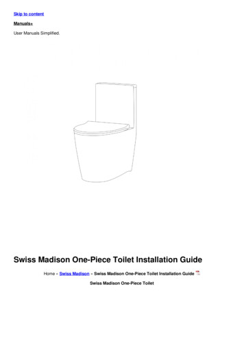
6. Parts DiagramITEMDESCRIPTION123TOILET BOWLTOILET TANK & LIDTOILET LID ONLYMACERATOR PUMP (INCLUDESITEMS 4-11)ACCORDION GROMMETELBOW, 1.5" RUBBERCHECK VALVE / ELBOW 1.5"3/4", 1" DISCHARGE ADAPTERCOUPLER, 1.5" X 1.5" RUBBERPLUG, 1/4 TURNCOUPLER, 1.5" X 2" RUBBEREXTENSION PIPE, WITH REARHUB SEAL456789101112 Copyright 2008 Liberty Pumps Inc.REPLACEMENT 79K001180K001181K001182K001183K001184All rights reserved.9
7. 2 Year Limited Warranty NOTE: Liberty Pumps, Inc. assumes no responsibility for damage or injury due to disassembly in the field. Disassembly,other than at Liberty Pumps or its authorized service centers, automatically voids warranty.Liberty Pumps, Inc. warrants that pumps of its manufacture are free from all factory defects in material and workmanshipfor a period of 2 years from the date of purchase. The date of purchase shall be determined by a dated sales receiptnoting the model and serial number of the pump. The dated sales receipt must accompany the returned pump if the dateof return is more than 2 years from the "CODE" (date of manufacture) number noted on the pump nameplate.The manufacturer's obligation under this Warranty shall be limited to the repair or replacement of any parts found by themanufacturer to be defective, provided the part or assembly is returned freight prepaid to the manufacturer or itsauthorized service center, and provided that none of the following warranty-voiding characteristics are evident.The manufacturer shall not be liable under this Warranty if the product has not been properly installed; if it has beendisassembled, modified, abused or tampered with; if the electrical cord has been cut, damaged or spliced; if the pumpdischarge has been reduced in size; if the pump has been used in water temperatures above the advertised rating, orwater containing sand, lime, cement, gravel or other abrasives; if the product has been used to pump chemicals orhydrocarbons; if a non-submersible motor has been subjected to excessive moisture; or if the label bearing the serial,model and code number has been removed. Liberty Pumps, Inc. shall not be liable for any loss, damage or expensesresulting from installation or use of its products, or for consequential damages, including costs of removal, reinstallation ortransportation.There is no other express warranty. All implied warranties, including those of merchantability and fitness for a particularpurpose, are limited to two years from the date of purchase.This Warranty contains the exclusive remedy of the purchaser, and, where permitted, liability for consequential orincidental damages under any and all warranties are excluded.7000 Apple Tree AvenueBergen, NY 14416Phone: (800) 543-2550Fax: (585) 494-1839www.libertypumps.com Copyright 2008 Liberty Pumps Inc.All rights reserved.10
Manual de instalación5755E00DBomba para inodoro Ascent ModelosASC-1Macerador, 115 V,1 fase, automáticoASC-2Tanque del inodoroASC-3Taza del inodoroÍndiceIMPORTANTE:1.) Información generalApunte el modelo, el número de serie y el código queaparecen en la placa de la bomba antes de instalarla paraque le sirvan de referencia en el futuro.2.) IntroducciónMODELO3.) InstalaciónSERIE4.) OperaciónCÓDIGO5.) Diagnóstico de problemas6.) Diagrama de piezasFECHA DEINSTALACIÓN7000 Apple Tree AvenueBergen, NY 14416Teléfono: (800) 543-2550Fax: (585) 494-1839www.libertypumps.com Copyright 2008 Liberty Pumps Inc. Todos los derechos reservados
1. Información generalLea con atención estas instrucciones antes de instalar la bomba. Todas las bombas Liberty se someten a pruebas en fábrica paragarantizar su funcionamiento. Siga estas instrucciones al pie de la letra para prevenir problemas de funcionamiento y asegurar largosaños de servicio satisfactorio. Riesgo de descarga eléctrica. Desenchufe la bomba siempre que vaya a moverla o a realizar algún ajuste.La bomba no se deberá instalar en un lugar clasificado como peligroso según el código eléctrico nacional (NEC) de los EstadosUnidos, ANSI/NFPA 70.Sólo personal calificado podrá encargarse de instalar las conexiones y cables eléctricos necesarios para montar la bomba. Esta unidad lleva un conector a tierra y un enchufe tomacorriente con conexión a tierra. Para reducir el riesgo de descargaseléctricas, el conector de puesta a tierra tiene que estar conectado a un panel de control a tierra o si lleva un enchufe a tierratendrá que enchufarse a un tomacorriente conectado a tierra. No derive los cables de puesta a tierra ni retire las espigas a tierra de los enchufes.No quite el cable ni la protección contra tirones, y no conecte canal para cables a la bomba.No use extensiones eléctricas.Se deberá instalar la unidad según las disposiciones del código eléctrico nacional (NEC) de los Estados Unidos y todos loscódigos y regulaciones locales que correspondan La bomba no se debe utilizar con agua a temperatura superior a los 49 C (120 F).No levante el tanque macerador tirándolo del cable eléctrico. Use el mango que se extiende de la cubierta.1-1INSPECCIÓN INICIALEl Ascent se envía en 3 paquetes separados: el tanque del inodoro (modelo ASC-2), la taza del inodoro (modelo ASC-3) y elmacerador (modelo ASC-1). Inspeccione inmediatamente las cajas para comprobar si se ha producido algún daño durante eltransporte. Tenga cuidado al abrirlas para no dañar el contenido. Saque todo el embalaje de protección del interior de lascajas.Revise bien este embalaje antes de desecharlo para asegurarse de que no haya ninguna pieza de repuesto en él. Haga unainspección visual de la bomba y de las piezas de repuesto. Compruebe que no haya ningún cable dañado, especialmente ala salida del tanque macerador. Informe de cualquier daño que pueda haberse producido y si falta alguna pieza. Si el rotor ylos discos están agarrotados debido a un prolongado período de almacenamiento, esta operación los soltará.1-2ALMACENAMIENTO ANTES DEL USOLas bombas Liberty ya vienen de fábrica listas para su instalación y uso. Pero si necesita almacenarla, no la saque de lacaja. Guárdela en un almacén o caseta limpio y seco a temperatura estable y cubra la caja y el recipiente para protegerloscontra el agua, el polvo, etc. Proteja los extremos de los cables (enchufes) contra la humedad.1-3IMPORTANTE. No deje que la unidad se congele. Si se permite que la vivienda quede a merced del frío durante los mesesde invierno, asegúrese de que el macerador y el inodoro sean evacuados de agua antes de abandonar la vivienda. Lostanques deberán ser llenados con líquido anticongelante para tuberías, para protegerlos de las condiciones decongelamiento.2. Introducción2-1El sistema de maceración puede recibir simultáneamente aguas residuales de diferentes instalaciones sanitarias, por ejemplo,bidet, fregadero, regadera, tina de baño o mingitorio, pero solamente de un sólo sanitario por unidad.2-2Los sistemas de maceración están diseñados para eliminar desechos humanos, papel higiénico y agua. No se deberán usarpara reemplazar sistemas de residuos de cocina, ni para desechar aguas residuales de electrodomésticos como lavaplatos ylavadoras de ropa.2-3Las instalaciones sanitarias conectadas al macerador deben estar ubicadas al mismo nivel. Copyright 2008 Liberty Pumps Inc. Todos los derechos reservados2
2-4El macerador es una bomba residencial para inodoros y accesorios de baño. La bomba del macerador se conecta a la salidaubicada en la parte posterior del inodoro. El sistema está formado por tres componentes principales: el macerador, la taza delinodoro y el tanque del inodoro.2-5El macerador también está compuesto de tres piezas principales: el recipiente que aloja el mecanismo de operación, unacámara de presión que se activa y se desactiva automáticamente y el motor de inducción que impulsa la cuchilla y el rotor.2-6ENTRADAS SANITARIAS: El macerador está equipado con dos entradas adicionales de 3.75 cm (1-1/2 plg), una a cada ladode la caja. Estas entradas, que incorporan una válvula de retención interna, se utilizan para conectar el tubo de drenaje deotras instalaciones sanitarias al macerador. Nota: En caso de que las entradas no se utilicen para otras instalaciones, sedeberán bloquear con los tapones incluidos.2-7TINAS DE BAÑO Y REGADERAS: Se puede utilizar cualquier tipo de tina de baño o sistema de regadera. Al instalar estasunidades, se deberá construir una plataforma de 15 cm (8 plg) de altura sobre la cual colocar la unidad. Esto ofrece suficienteespacio para colocar un colector de agua en forma de P con inclinación hacia las entradas de aguas residuales. Para lainstalación de la regadera, los fabricantes a veces ofrecen bases elevadas prefabricadas. NOTA: La distancia real entre elcolector de agua en P de la instalación adicional y el macerador determinará el espacio libre necesario para instalar dichocolector y la elevación requerida para asegurar un flujo mínimo de .6 cm por 30 cm (1/4 plg por pie).2-8CICLO NORMAL DE OPERACIÓN: Cuando se jala de la cadena o a medida que se desagua la tina, regadera o lavabo, elagua y las materias de desecho ingresan en la unidad y el nivel de agua comienza a elevarse, activando un microinterruptoren la cámara de presión. Por seguridad, nunca se deberá activar el macerador con la tapa desmontada.3. InstalaciónNOTA: Todas las instalaciones se deberán hacer según los códigos federales, estatales y locales. Se recomienda que uninstalador certificado o calificado se ocupe de llevar a cabo estas operaciones.3-1PREPARACIÓN DEL MACERADOR PARA LA INSTALACIÓN3-23-1-1Empuje el sistema de tapón/codo del inodoro hacia el ojal de desagüe en la tapa del tanque. Oriente el codo a sugusto y asegúrelo con la abrazadera para manguera incluida.3-1-2Instale el ojal adaptador al codo de desagüe con una abrazadera para manguera. Este adaptador permite laconexión de un tubo PVC 40 de 3/4 ó 1 plg al sistema.3-1-3Instale un ojal de goma de 1-1/2 plg al cilindro
Installation Manual 5755E00D Ascent Toilet Pumping System Models ASC-1 Macerator Unit, 115V, 1 phase, Automatic ASC-2 Toilet Tank ASC-3 Toilet Bowl . 2-1 The macerating system can simultaneously receive wastewater from several sanitary fixtures, e.g. bidet, sink, shower, bathtub, or urinal, but only one water closet per unit. .