Transcription
Installation Manual5755000EModels:Ascent II-ESWComplete system - elongated toiletAscent II-RSWComplete system – round front toiletContents1.) General Information2.) IntroductionIMPORTANT:3.) Installation4.) OperationPrior to installation, record Model, Serial Number,and Code Number from pump nameplate for futurereference.5.) MaintenanceMODEL:SERIAL:6.) Troubleshooting ChartINSTALLATION DATE:7.) Warranty7000 Apple Tree AvenueBergen, NY 14416Phone: (800) 543-2550Fax: (585) 494-1839www.libertypumps.comMacerator UPC listed, file 5771;Toilet UPC listed, file 8056;Toilet Meets EPA WaterSense Criteria[Certifications apply to 115V Models Only] Copyright 2013 Liberty Pumps Inc.All rights reservedASME A112.3.4CSA B45.9
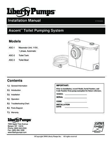
1. General InformationBefore installation, read the following instructions carefully. Each Liberty pump is individually factory tested to ensureproper performance. Closely following these instructions will eliminate potential operating problems, assuring years oftrouble-free service.Explosion Hazard and/or Health Hazard during installation or maintenance 1-1Risk of electric shock. Always disconnect the macerator from the power source before handling or makingadjustments.These pumps are not to be installed in locations classified as hazardous in accordance with the National ElectricCode, ANSI/NFPA 70.Qualified personnel should only make the electrical connections and wiring for a pump installation.This pump is supplied with a grounding-type attachment plug. To reduce the risk of electric shock, be certain that it isconnected to a properly grounded, grounding-type receptacle.This product must be connected to a ground fault circuit interrupter (GFCI) receptacle or circuit breaker.Do not bypass grounding wires or remove ground prong from attachment plugs.Do not use an extension cord.The installation must be in accordance with the National Electric Code and all applicable local codes and ordinances.The Macerator has a large opening to accept the discharge hub of a rear discharge toilet. DO NOT place hand orother objects into this opening even if unit is unplugged. The macerator has razor sharp cutters within this opening.Decorative covers must be installed for operation, a safety device is integrated into the covers to prevent unintendedoperation. The unit may start when energized the first time.Explosion hazard during installation. PVC cleaners, primers, and cements can release explosive vapors. Theseheavier than air vapors can accumulate in the tank. The heat of soldering or sweating copper or other metal pipe canignite these vapors causing a violent explosion. If the unit is to be connected to copper discharge or vent piping, allsolvent welded PVC joints must be allowed to cure a minimum of 24 hours. The access cover must be removed toallow the macerator to be thoroughly ventilated prior to sweating copper pipe near the unit.Do not use macerator in water over 104 F.Do not lift macerator by the power cord.Do not use an air admittance valve or a mechanical springloaded venting device.INSPECTION UPON RECEIPT.The Ascent II is shipped in 3 separate packages, the toilet tank(model: Ascent II - TW), toilet bowl (model: Ascent II – RW or EW)and macerating unit (model: Ascent II - MUW). The shippingcontainers should be immediately inspected for damage that mayhave occurred in shipment. Exercise care in opening the shippingcontainer to avoid damage to the contents. Remove any blockingand packaging from within the containers.Check all packaging for spare parts before discarding. Visuallycheck the macerating unit and any spare parts for damage.Check for damaged electrical wires, especially where they exit themacerating tank. Report any damage or shortage of parts toLiberty Pumps 1-800 543-2550.ASCENT - EWList of included parts:Toilet BowlToilet TankMaceratorMacerator tankRubber couplings with clampsReducing bushings9-volt batteryAllen wrench - 3/16”Grease packet Copyright 2013 Liberty Pumps Inc.ASCENT - RWASCENT - MUWAll rights reserved.2
1-2STORAGE BEFORE USELiberty products are shipped from the factory ready for installation and use. If storage is necessary, the pump should remain in its shippingcontainer. It should be stored in a warehouse or other area that is clean, dry and temperature-stable. The pump and packaging should becovered to protect it from water, dirt and dust.IMPORTANT: After installation, do not allow the pump to freeze. If the home is allowed to freeze during winter months, ensure the maceratingunit and toilet are evacuated of water before closing the home. The tanks should be properly winterized and filled with plumber’s anti-freeze toprotect against freezing conditions. The battery should also be disconnected.2. Introduction2-1MACERATING SYSTEM: The macerator is designed to accept wastewater from a rear discharge toilet but can also simultaneously receivewastewater from several sanitary fixtures like a sink, shower, bathtub, or urinal (a single bathroom group). However, only one water closet(toilet) per unit may be connected.2-2USAGE: The macerating system is designed for the disposal of human waste, toilet paper and water. It is not intended for kitchen waste, nor is itintended to be used for the disposal of wastewater from such pumped appliances as dishwashers and clothes washers. This product is notdesigned for emptying large pools or spas.2-3TOILET: The toilet works as a conventional flushing toilet and needs no special maintenance in normal use. All standard cleaners can be usedjust as with a standard conventional toilet.2-4BATH LAYOUT: Sanitary fixtures connected to the macerating system must be located on the same floor level.2-5AUXILIARY INLETS: The macerator unit is equipped with two inlet ports, one on each side. These ports are designed for standard PVC pipe.Included with the system are two 2” flexible PVC couplers and 1-1/2” reducing bushings. These inlets, which incorporate an internal checkvalve, are used to connect the drainpipe of other sanitary fixtures to the macerating pump unit. Typically, the 2” drain is used with shower stallsonly. A tub, shower/tub combo, or sink would use a 1-1/2” drain line. From the factory, the auxiliary inlets are plugged - if the port is to be usedthe plug must be removed. The plug can be removed by rotating until the rib is vertical and then pulling outward. If the unit has been stored forsome time pliers may be needed to assist in removal.2” coupler1-1/2” reducing bushing2-6BATHTUBS AND SHOWER STALLS: Any regular bathtub up to 100 gallons or shower can be used. When installing these fixtures, build a 6” highplatform on which the fixture is placed. This gives enough space for a p-trap and slope toward the Macerator’s auxiliary inlets. When installinga shower, manufacturers sometimes offer a pre-fabricated raised shower base. NOTE: The actual distance between the p-trap of theadditional fixture and Macerator determines the necessary clearance to install the p-trap and elevation required to ensure a minimum pitch of¼” per foot drop.2-7OPERATION: The macerating system starts automatically once the toilet is flushed or liquid from other fixtures enters the unit. It automaticallyshuts-off once the contents have been pumped away. Run times will vary depending on inflow and source. See Section 2-9 for normaloperating cycles.2-8USER INTERFACE: The macerator has a user interface (touchpad with LED’s) located on the top left side of the unit. This label contains threeLED lights: GREEN – identifies the unit has power, YELLOW – 9-volt battery needs to be replaced, and RED – alarm. If the unit is unable toevacuate the holding tank or cannot keep up with the incoming flow the red light and audible alarm will activate. The label has two pushbuttons – a “Push to Silence” which will silence the audible alarm and a “Push to Run” which will over-ride the internal switch and manually runthe macerator and pump. Copyright 2013 Liberty Pumps Inc.All rights reserved.3
2-9NORMAL OPERATING CYCLE: The macerator’s IST switch is capable of distinguishing between different modes of operation and optimizes therun time accordingly. Advanced run detection will energize the cutters once the unit detects a flush. In doing so, the cutters are spinning atmaximum speed (rpm) prior to fluid and debris reaching the cutting system. The unit may pulse during a shower or draining a bathtub becausethe macerator can pump at a higher rate than the incoming flow.2-10 ALARM: The macerator has an integral alarm that will sound if the unit cannot remove liquid or keep up with incoming water. If the alarm sounds,a number of conditions could exist; please see the trouble shooting guide to determine the cause and solution. A silence button located on theuser interface touchpad will stop the audible alarm. The alarm light will continue to illuminate. Discontinue using the product until the problemhas been identified and resolved. In the event of a power outage, a 9-Volt battery will power the alarm. (Note: In the event of a power outageand if necessary, the macerator will accept two flushes prior to alarm activation. After that, the unit should not be used again until the power isrestored.) The alarm automatically resets once a normal cycle is performed. If the yellow light is illuminated on the LED touchpad, the 9 voltbattery needs to be replaced. The expected life of the supplied battery is 5 to 7 years.2-11 ACCESS COVER: The macerator has an access cover that can be removed to gain access to the pumping and macerating cartridge to removedebris or perform maintenance. Once the right hand decorative cover and access cover have been removed, the cartridge can be slid towardsthe opening to provide access to the basket and cutting mechanism. The blades or entire cutting base can be replaced if needed. See themaintenance section 4-3 of this manual for detailed instructions.3. Installation 3-1NOTE: All installations should be done in accordance with federal, state and local codes. It is recommended that a certified or qualifiedinstaller perform these operations. Do not use an air admittance valve or a mechanical spring-loaded venting device.The bathroom layout should be designed prior to installation.a)Make certain the power source (GFCI receptacle) is within range of the macerator’s 8’ power cord. The cord can be configuredto exit the unit on either the left or right side. Do not use an extension cord. When exiting the left side of the macerator the ventflange must be removed so the cord can be routed between the positioning clips. Reinstall vent flange after routing the cord.b)If possible, the right side of the macerator should remain unobstructed. An access cover is located under the decorative coverthat allows access to the cutting mechanism. In the event of a jam, the decorative cover as well as the access cover will needto be removed from the macerator and working room to do so would be beneficial.c)Auxiliary inlet ports are located on either side towards the back of the macerator’s tank. These ports can accept waste fromsink or tub/shower.d)An optional discharge extension allows the macerator to be positioned behind a wall. For instance, the macerator could bepositioned on the floor of a linen closet or utility room. DO NOT fully frame unit into a wall -- access to macerator must bemaintained.e)The macerator features Quickfliptm discharge and vent flanges that can be oriented in a vertical or horizontal orientation to bestfit your installation.f)A sink should be plumbed into one of the auxiliary inlets and not the discharge line of the macerator even if elevations wouldallow such an installation. The discharge line is pressurized and the plumbing system needs to accommodate this.g)The water supply line for the toilet tank is located on the left side. When roughing in, pay attention to allow for the macerator.h)Long downward pitched runs of discharge piping, or piping where the point of discharge is at a lower elevation than themacerator unit, should be designed to prevent siphoning from the macerator tank.i)Rough in dimensions – The toilet hold down fasteners should be located 16” from the wall and spaced 7” apart. This assumesa typical baseboard of ¾” x 5.5” with ¾” quarter round. Actual baseboard dimensions must be taken into account during theinstallation and thus rough in dimensions might change. Copyright 2013 Liberty Pumps Inc.All rights reserved.4
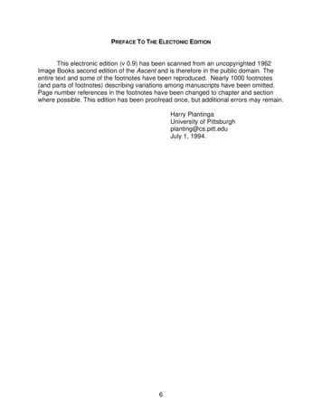
3-2PREPARING THE MACERATING PUMP UNIT FOR INSTALLATION3-2-1The decorative covers are shipped from the factory assembled on the unit. However, during the installation both covers must beremoved from the macerator. The auxiliary inlet couplers, Allen wrench, grease packet, hardware, and 9-volt battery can be found ina depression in the access cover.3-2-2Auxiliary inlets should be plumbed using the supplied aux. inlet couplings and/or reducing bushing when connecting to either 2” or 11/2” standard sch 40 pvc pipe. The plug must be removed by turning until the rib is vertical and pulling outward, pliers might berequired if unit has been stored.3-2-3Both the discharge and vent flanges are shipped from the factory in the horizontal orientation. If the installation allows for a verticalorientation, the four screws must be removed from each in order to flip the flange. The decorative cover will need to be modified withthe use of a hole saw and cutters to remove material. A template is provided on the underside of the decorative cover.3-2-4When installing the toilet to the macerator, first apply a small amount of silicone grease (grease package is provided) to the rubbersealing lip of the macerator. This will provide for a very simple and smooth installation.Discharge FlangePVC solvent weld1" sch. 40 PVC pipeVent FlangePVC solvent weld1-1/2" sch. 40 PVC pipeDischarge and vent flangesIn horizontal orientation3-3Discharge and vent flangesIn vertical orientationSYSTEM ASSEMBLY3-3-1Schematics: Typical Installation Diagrams. Refer to these diagrams when needed during the assembly process. Installations mayvary per local plumbing and electrical codes. Also, discharge and vent pipe routing can vary per installation.3-3-2Place the macerator in the desired location and connect all inlet and outlet waste piping to the unit. The non-inlet side of the tankshould be towards the wall to ensure proper toilet placement. Copyright 2013 Liberty Pumps Inc.All rights reserved.5
3-43-3-3Assemble the toilet in accordance to the installation manual(s) provided with it. Be careful when tightening fasteners as to not crackthe porcelain.3-3-4To mount the toilet to a concrete floor, drill two holes approximately 2-1/4” deep with a 5/16” masonry drill bit. Insert plastic plugsinto holes. If the floor is wood, bore a pilot hole with a ¼” drill bit.3-3-5Place the toilet in front of the macerating tank and apply silicone grease to sealing lip of macerator. Then slide the discharge hub ofthe toilet into the rubber sealing ring of the macerator.3-3-6Place the toilet over the holes in the floor. Slip the plastic china protectors over the lag screws ensure proper orientation. Tighten lagscrews (do not over tighten) and snap plastic caps in place.3-3-7Connect the water supply line to the fill valve, located directly below the flush lever, on the bottom of the toilet tank.CONNECTION TO THE DISCHARGE AND VENT FLANGES3-4-1The Macerator has a PVC discharge flange with an integrated check valve that can be configured in a vertical or horizontalorientation. Standard 1” schedule 40 PVC pipe can be solvent welded directly to the flange. Excessive amounts of glue should beavoided. The check valve can be removed from the flange if required. Replacement flanges can be ementParts/3-4-2A “full-port” ball or gate valve and a union should be installed in the discharge pipe to facilitate the removal of the macerator or toperform maintenance if required. In addition, a drain off point is also recommend to allow the discharge piping to be drained ifrequired.3-4-3The macerator is equipped with a PVC vent flange, which can be configured in a vertical or horizontal orientation. Standard 1-1/2”Schedule 40 PVC pipe can be solvent welded directly into the flange.3-4-4The macerator must be vented to allow for proper toilet flush performance. Depending on the installation, the product should eitherbe connected to the stack vent of the dwelling or vented (plumbed) directly outside.3-4-5***Do not use an air admittance valve or a mechanical spring-loaded venting device, as these devices are one-way3-4-63-5valves. The air pressure in and outside the macerating pump unit must be equal, a “cheater” vent will obstruct the airflow in onedirection and prevent proper toilet function.The Macerator is not designed to support the discharge and vent piping; proper pipe hangers are required.CONNECTION TO THE SOIL-STACK OR SEWER3-5-1The macerator has a shut-off head of 36 feet. All frictional losses from horizontal runs and elbows need to be accounted for. Theminimum flow rate for 1” PVC sch. 40 pipe is 5 gal/min compared to 3 gal/min for ¾” PVC pipe. If you require a vertical lift, it shouldprecede any “horizontal” run and should commence as near as possible to the discharge of the macerator. Once you have startedthe horizontal run, you may not change directions in a vertical manner.NOTE: Friction losses from horizontal runs without ¼” per foot pitch will reduce the amount of vertical liftthe system is capable of handling. See sections 3-5-2 and 3-5-3. Consult factory for proper sizing if youhave long runs or multiple elbows. Phone: 1-800-543-2550.3-5-2The discharge piping can be made from ¾” or 1” diameter CPVC or PVC pipe. Use long turn bends and not elbows where possible.The connection to the soil-stack or sewer pipe should be made with an approved wye fitting. Copyright 2013 Liberty Pumps Inc.All rights reserved.6
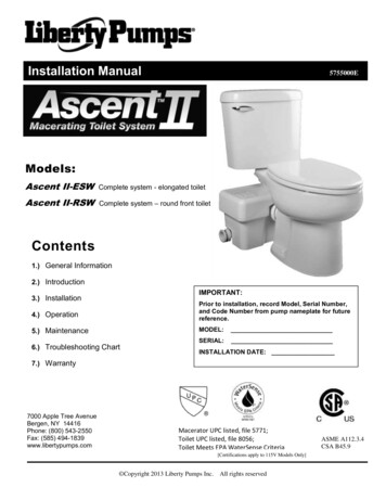
3-5-3If you wish the unit to pump vertically and horizontally you may calculate 3 feet of vertical lift is equivalent to 30 feet of “horizontal”run. Each bend or change of direction gives a pressure drop, which must be calculated into the total head of the unit. As anestimate, reduce discharge height by 3 feet for each 90 bend.For example: 1” SCH. 40 PVC pipe is used for the discharge and runs horizontally for 1’; then turns 90 and rises 5’ vertical.Then it travels horizontal with another 90 turn (3 turns in total) and connects with the soil-stack. See illustration below.Calculations:Total vertical lift 5’ 5’ verticalTotal Horizontal run 43’ 4.3’ verticalTotal of three 90 elbows 9’ verticalNow add the three together we get 18.3’ of vertical lift. Reading theperformance curve below indicates the application would result in a flowrate of 23 gal/min(60Hz).All fixtures must be properly ventedTub / Shower should be installedon a riser to accommodate the P trap Copyright 2013 Liberty Pumps Inc.All rights reserved.7
3-6CONNECTION TO ELECTRICAL SUPPLY3-6-1All wiring should be done in accordance with the applicable electrical codes. The macerating system requires a properly sizedsingle-phase GFCI (ground fault circuit interrupter) type receptacle. Receptacle should be installed in accordance with local andstate electrical codes. It is recommended that the receptacle be 40 inches away (in a straight line) from a shower or bathtub. Ifinstallation is performed in a basement, the receptacle should be 48 inches from the floor.3-6-2If the electrical power receptacle (outlet) is in close proximity to the macerator, the “extra power cord” can be coiled and tuckedaway in a large depression designed into the access cover that is located under the right decorative cover.Risk of electric shock. This pump is supplied with agrounding-type attachment plug. To reduce the risk ofelectric shock, be certain that it is connected to aproperly grounded, grounding-type receptacle.3-73-8EXTENSION PIPE3-7-1To install the macerator behind a wall, a Liberty extension pipe kit # K001184 (soldsperately) will be needed. Included in the kit are an 18.75” long extension pipe, adecorative trim ring, and a grease packet. Rubber rings seal both ends of the extensionpipe. To prevent tearing, always grease both seals prior to installing the pipe. Slipthe decorative trim ring onto the pipe. To install the pipe, no fasteners are required, slipthe extension pipe over the toilet’s discharge, and then insert the pipe into themacerator. To finish the installation, fasten the toilet to the floor and secure themacerator discharge and vent piping. For proper flushing performance, ensure that thebase of the toilet is not below the base of the macerator. Check the extension pipe witha level, and verify that the pipe is either level or sloped towards the macerator unit andaway from the toilet.3-7-2Liberty recommends only one extension pipe be used.INSTALLATION TIPS3-8-1PIPE SUPPORTS: All sanitary pipe work must be supported in accordancewith the pipe manufacturer’s recommendations. Avoid dipping or trapping,which may cause the buildup of residual “solids” and subsequent blockage.3-8-2BENDS: Wherever possible, long sweeping bends should be used. Do not useshort elbows. If sweeping 90 elbows are not available, use two 45 elbows tomake a 90 turn.3-8-3VERTICAL PIPING FIRST: If vertical lift is required, this must precede thehorizontal pipe run.3-8-4BATTERY: Battery must be installed AFTER the macerator is connected to theAC power supply. Failure to follow this procedure could result in the unit notfunctioning properly.3-8-5DIRECTLY VERTICAL: All vertical lifts should rise as close to the maceratoras possible, allowing only for the need to clear the toilet tank; the initial horizontal run should not exceed 12”.3-8-6NO DIAGONAL “UPHILL” PIPE RUNS: All discharge piping from the unit should run either directly vertical or in a horizontal plane(with a minimum ¼” per foot drop) to the point of discharge. Pipe work must not be installed with a diagonal upward slope from theunit to the point of discharge.3-8-7EASY ACCESS: The unit should be accessible and removable in the event of maintenance being required. During the installation, afull-port ball valve should be installed near the discharge flange to allow easy service of the unit.3-8-8GRAVITY FALL: The unit accepts wastewater by gravity; it does not “vacuum” in water. All inlet pipe work must have a positivegravity fall (1/4” per foot drop minimum). All horizontal piping from the macerator must also have a ¼” per foot drop to allow freedrainage when the pump stops.3-8-9SOIL STACK CONNECTION: All discharge pipe work must be connected to the soil stack by an appropriate and approvedconnection like a “tee” or “y” fitting.3-8-10PIPE WORK: All pipe work should be copper, PVC, or CPVC. Do not use flexible piping. Hangers should not be less than 4 feetapart to prevent pipe rattling.3-8-11FLUSHING: Macerator is designed to work with a low flow toilet (1.28 gallons per flush).3-8-12DISCHARGE: Never discharge directly into an open drain, fixture, manhole or rainwater drainpipe. It is illegal, as it constitutes ahealth hazard. Direct connections into sanitary waste systems only shall be acceptable.3-8-13FREEZING: Ensure all pipe work susceptible to freezing is adequately insulated or heated. In unheated buildings, the toilet, pipingand macerating unit must be properly winterized. Use plumbers’ anti-freeze or drain completely.3-8-14ELECTRICITY: The macerating system must be connected to a Ground Fault Circuit Interrupter (GFCI).Installed positionBefore attempting any maintenance or servicing, the unit must be disconnected from the power source.3-8-15SHOWER: The water height will be 4.5” in the Macerator tank before the unit starts pumping. The shower stall floor must be wellabove this level, Liberty recommends at least 6” - 8” to ensure proper shower drainage and prevent any backflow. Copyright 2013 Liberty Pumps Inc.All rights reserved.8
4. Operation4-14-24-3ACTIVATING THE UNIT4-1-1Ensure that the toilet / tank have been assembled per the instructions provided with the toilet tank.4-1-2Ensure any ball or gate valve in the discharge line is in the open (full flow) position.4-1-3Open the shut-off valve and let the toilet tank fill up. Look for leaks at connections.4-1-4Ensure the macerating unit has both decorative covers installed and is plugged in with the power supply turned on.The green light should be illuminated. If the green light is blinking, check to confirm the decorative covers areproperly seated.4-1-5Deposit a few sheets of toilet paper into the bowl and flush the toilet. There should be no paper remaining in the bowlafter the flush. This should be repeated several times.4-1-6Either flushing the toilet or the height of water in the tank activates the Macerator’s adaptive switch system. The unitwill turn on shortly after the toilet is flushed or when a water depth of 4.5” is achieved. The duration of operation willdiffer depending upon the installation. Note, the Macerator may not run immediately upon sink usage.CAUTIONARY NOTES4-2-1The macerating system is designed for human waste and toilet paper.4-2-2Do not dispose of acids, alkalis, solvents, oils, paint, paint strippers, food waste, and cotton swabs. Off-the-shelf toiletcleansers will normally not hurt the macerating unit. During cleaning or when using a plunger the macerator couldturn on.4-2-3Do not hang bleach blocks or hypochlorite cleaners in the toilet tank. These solutions have been shown todeteriorate the plastic and neoprene components of the flush and fill valves, and may cause leaks.4-2-4In the event of a power loss, the toilet can be used twice. Use of sanitary fixtures like a sink should be limited. Do notuse shower or tub as the macerating unit will fail to pump until the power is restored.MAINTENANCEThe macerator is designed such that every component can easily be serviced or replaced if required.Risk of electric shock, always disconnect the macerator from the power source before handling or makingadjustments. Health hazard: sharp blades within unit, wear rubber gloves.4-3-1Decorative covers: Both the right and left decorative covers sit on the product and are retained with some simple clipsand posts. The right side can be removed by pulling it horizontally away from the macerator and then lifting vertically. Theleft decorative cover is secured and positioned by two mating posts on the main cover.Left sideRight side4-3-2Discharge and Vent Flanges: Both the discharge and vent flanges are fastened tothe main cover and can be removed by unscrewing the four fasteners and pulling theflange away from the main cover. Copyright 2013 Liberty Pumps Inc.All rights reserved.9
4-3-3Check Valve: The discharge flange has an integrated check valve. The valve is held in place by a support backing platethat is also connected to the discharge hose. To access the check valve, first remove the discharge flange from the maincover by removing 4 screws. Then, remove the hose followed by the two screws. The hose nipple can then be separatedfrom the flange by pulling it outward. The check valve snaps onto the hose nipple. When reinstalling, the hinge of thecheck valve must be aligned with the “notch” in the hose nipple or backing plate. After installation of the hose nipple,confirm the check valve opens completely.4-3-4Access cover: The access cover is secured to the main cover with five fasteners. If required, use the 3/16 Allen wrenchsupplied to loosen the fasteners. Once the screws have been removed, the access cover can be lifted upward. Somemanipulation might be necessary if the Macerator is located directly under the toilet’s reservoir tank.Once the access cover is removed pull the powercartridge towards openinga)b)c)d)Once the access cover is removed, the power cartridge can be slid towards the opening by grasping the handle ofthe basket and pulling to the right towards the opening. In some instances, debris might be caught between the tankand the basket so some manipulation might be required.With the power cartridge fully slid over, the cutters should be in view at the center of the basket. Any obstruction orobject can be removed at this point. The cutters are very sharp and extreme caution should be used.To replace the cutters the 3/16 Allen wrench (supplied) should be inserted into one of the holes located on thebasket floor. This will create a wedge preventing the blade assembly from turning. The locking fastener can beunscrewed with the use of a 7/16” socket (1/4” drive). Once loose, the screw and cap can be removed by pullingupward which exposes the two razor blades. Liberty Pumps recommends stainless steel blades, although anycommon utility knife style razor blade with two holes can be used as a replacement. When replacing the razor bladessimply insert the blade onto the two pins. The cap and screw should then be replaced.The base of the cutting cartridge can be replaced as well. After removing the razor blades a thin slotted screwdrivercan be inserted into the center hole and once engaged the base can be rotated counterclockwise until it is free. Copyright 2013 Liberty Pumps Inc.All rights reserved.10
To remove capUnscrewfastenerScrewCapUtility bladeBasePlace Allenwrenchin hole to preventcutter fromturning4-3-5Cutting and health hazard,caution must be used whenhandling razor blades.Accessibility to Motorized cartridge:The motorized cartridge can be accessed through the access opening or removal of the main cover.1)Removal of power cartridge through the access opening:Once the access cover has been removed and the basket is slid towards the opening, the fourfasteners securing the basket can be unscrewed. The basket can then be removed through theopening followed by the power cartridge.2)Removal of power cartridge by disassembly of macerator:If a ball valve was installed in the discharge line, it should be closed to eliminate the possibility ofwaste discharging from
Ascent II 7000 Apple Tree Avenue Bergen, NY 14416 Phone: (800) 543-2550 Fax: (585) 494-1839 www.libertypumps.com Contents 1.) General Information 2.) Introduction 3.) Installation 4.) Operation 5.) Maintenance 6.) Troubleshooting Chart 7.) Warranty Installation Manual 5755000E Models: Ascent II-ESW Complete system - elongated toilet