Transcription
SITE-TO-SITE LAYER 2 VPNWITH PPP BCPLay Minh (Makito)CCIE # 47682, MikroTik Certified Trainer, MikroTik ConsultantApril 24th, 2017MikroTik User Meeting, Phnom Penh, Cambodia
ABOUT ME Lay Minh (Makito)MikroTik Certified Trainer & Consultant Chief Technology Officer @ i-BEAM Experiences: 12 years in ISP industry since 2005 Billing solutions for service providers ISP core network design and operations Certifications: Areas of interest: BGP, MPLS, IPv6CCIE # 47682
AGENDAAbout VPN VPN Types VPN Topologies VPN Implementation
ABOUT VPN VPN stands for Virtual Private Network. A cost-effective technology that can virtually connect youfrom one location to another location (usually via Internet)for sharing resources on the networks:File sharing Remote access to company intranet or ERP system Secured access with authentication and encryption
ABOUT VPN (CONT.) Traditionally we need rent a leased line for connecting toremote locations, BUT depends on the geographicaldistance some connections might not be available or might not be practical to implement with reasonable budget With latest technologies, MPLS VPN is also anotheralternative, it is simple (for customers) and the quality isguaranteed, BUT there are still a few points to consider:Difficult to change ISP if you are unhappy with them Your ISP might not cover all locations that you want Poor interop capability when service is covered by multiple ISPs
VPN TYPES Remote AccessFor individual employee to access company’s resources fromhome or remote locations VPN Server is usually VPN router at office VPN Client is usually employee’s PC/laptop at home Site-to-site For sharing company’s resources by connecting:Head Quarter to Branch Office Office 1 to Office 2 etc. VPN Server is usually VPN Hub router at Head Quarter VPN Client is usually VPN Spoke router at Branch Office
SITE-TO-SITE VPN TYPES Site-to-site Layer 2 VPNSite-to-site Layer 3 VPNAll sites share same LAN IP subnetEach site has different LAN IP subnetBroadcast domain is end-to-endeverywhereBroadcast is not possiblebetween sitesCentralized DHCP ServerIndependent DHCP Serverin each siteCentralized Internet GatewayPossible individual Internet Gatewayin each siteBased on bridgingNo routing requiredStatic Route orDynamic Routing Protocol required Site Location Office
SITE-TO-SITE VPN TOPOLOGIES Common VPN Topologies:Hub-and-spokeFull MeshPartial Mesh
SITE-TO-SITE VPN TOPOLOGIES(CONT.) Hub-and-spokeFull/Partial Mesh1 or more Hub routersEvery router is at the same levelHub routers are usually located at HQ Their relationship is peer-to-peerEvery Spoke router establishes onlyVPN tunnel to HubEvery router has VPN tunnel to otherroutersNumber of VPN tunnels:Hub routers X Spoke routersNumber of VPN tunnels: Full Mesh: n (n – 1) / 2n Number of routers Partial Mesh: depends on numberof actual VPN links in the designEasy to deploy and maintainHeavy task on deployment andmaintenanceSingle point of failureGood redundancyLow risk on bridging loopHigh risk on bridging loopUsually STP is used
VPN DIAGRAMDue to the popularity in real world and ease ofimplementation, in this presentation, we will only focus onSite-to-site Layer 2 VPN with Hub-and-spoke topology. For simplicity, we will setup only 1 Hub router (HQ) and 2Spoke routers (Branch01 and Branch02) for our sample config.
L2VPN METHODS IN ROUTEROS Ethernet over IP (EoIP) BridgingRequires Public IP is every location Requires static configuration on both Hub router and Spokerouter for each EoIP Tunnel Easy to configure, but hard to maintain Point to Point Protocol (PPP) Bridge Control Protocol (BCP)Only Hub router needs Public IP Hub router configuration is one time work, for each new location,only Spoke router needs to be configured Client-Server type VPN, requires more efforts on initialconfiguration
VPN CONFIGURATIONEOIP METHOD HQ: 3 steps to complete1.2.3. Create Bridge InterfaceCreate EoIP Tunnel to each BranchAdd your LAN interface and EoIP Tunnel as Bridge Portsto the Bridge you created in Step 1Branches: 3 steps to complete1.2.3.Create Bridge InterfaceCreate EoIP Tunnel to HQAdd your LAN interface and EoIP Tunnel as Bridge Portsto the Bridge you created in Step 1
CONFIGURATION – EOIPHQ (STEP 1) Create a VPN Bridge:Bridge menu [ ] Interface Name: BR-VPN (arbitrary) STP Protocol Mode: rstp
CONFIGURATION – EOIPHQ (STEP 2) Create a EoIP Tunnels toBranch01: Interface menu [ ] EoIP TunnelLocal Address is Public IPof the HQRemote Address is PublicIP of Branch01Tunnel ID is unique forevery EoIP Tunnel, mustbe same between peersIPsec Secret can beconfigured if you needencryption, must be samebetween peers
CONFIGURATION – EOIPHQ (STEP 2, CONT.) Create a EoIP Tunnels toBranch02: Interface menu [ ] EoIP TunnelLocal Address is Public IPof the HQRemote Address is PublicIP of Branch02Tunnel ID is unique forevery EoIP Tunnel, mustbe same between peersIPsec Secret can beconfigured if you needencryption, must be samebetween peers
CONFIGURATION – EOIPHQ (STEP 3) Add LAN interface (ether2) and EoIP Tunnels to VPN Bridge: Bridge menu Ports [ ]
CONFIGURATION – EOIPBRANCHES (STEP 1) Create a VPN Bridge:Bridge menu [ ] Interface Name: BR-VPN (arbitrary) STP Protocol Mode: rstp
CONFIGURATION – EOIPBRANCHES (STEP 2) Create a EoIP Tunnels toHQ: Interface menu [ ] EoIP TunnelLocal Address is Public IPof the BranchRemote Address is PublicIP of HQTunnel ID is unique forevery EoIP Tunnel, mustbe same between peersIPsec Secret can beconfigured if you needencryption, must be samebetween peers
CONFIGURATION – EOIPBRANCHES (STEP 3) Add LAN interface (ether2) and EOIP-HQ to VPN Bridge: Bridge menu Ports [ ]
VPN CONFIGURATIONPPP BCP METHOD There are a few kinds of PPP Tunnels supported inRouterOS: Point to Point Tunneling Protocol (PPTP) Layer 2 Tunneling Protocol (L2TP) Well-knownCan combine with IPsec for encryptionSecure Socket Tunneling Protocol (SSTP) Very secure, can bypass most of the firewall, but slowBCP is Bridge Control Protocol, allows sending EthernetFrame over PPP. Due to all PPP Tunnels’ configurations are quite similar,we will show only L2TP example in this presentation.
VPN CONFIGURATIONPPP BCP METHOD (CONT.) HQ: 6 steps to complete1.2.3.4.5.6. Create Bridge InterfaceAdd LAN interface to the BridgeCreate IP Pool for VPN point-to-point IPsCreate PPP Profile by assigning the Bridge in the profileCreate PPP Secret using PPP Profile you created in Step 4Enable L2TP VPN Server with Multi-Link PPPBranches: 4 steps to complete1.2.3.4.Create Bridge InterfaceAdd LAN interface to the BridgeCreate PPP Profile by assigning the Bridge in the profileCreate L2TP Client Interface with Multi-Link PPP
WHAT IS MULTI-LINK PPP? RFC 1990 Multi-Link Point to Point Protocol (MP, Multi-Link PPP,MultiPPP or MLPPP) is a method of splitting, recombining, andsequencing data across multiple logical data links. https://tools.ietf.org/html/rfc1990Source: https://wiki.mikrotik.com/wiki/Manual:MLPPP over single and multiple linksIn short, for Layer 2 VPN to work, Ethernet frames have totravel through VPN tunnelBUT generally VPN MTU is smaller than size of Ethernet frame SO in order to have “bigger MTU”, we can establish multiple PPPtunnels and combine them together, so-called Multi-Link PPP
CONFIGURATION – PPP BCPHQ (STEP 1 & 2)1.Create a VPN Bridge:Bridge menu [ ] Interface Name: BR-VPN(arbitrary) STP Protocol Mode: rstp 2.Add LAN interface(ether2) as Bridge Ports:Bridge menu Ports [ ] Interface: ether2 Bridge: BR-VPN
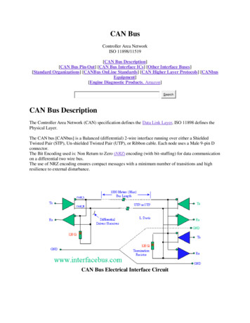
CONFIGURATION – PPP BCPHQ (STEP 3) Create IP Pool for VPN point-to-point IP: IP Pools [ ]When Branches connected to VPN, they will get IP fromthis IP range, and these IPs can be used for monitoring.
CONFIGURATION – PPP BCPHQ (STEP 4) Create PPP Profile, enableBCP by assigning VPNBridge in the PPP Profile:PPP menu Profiles [ ] Local Address is HQ’s VPNP2P IP Remote Address isBranches’ VPN P2P IP range By assigning BR-VPN toBridge, BCP will be enabledon this VPN Server, and allVPN Clients with BCPcapability will be addedautomatically to the Bridgewhen connected
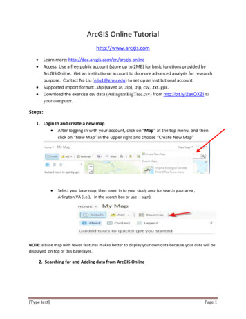
CONFIGURATION – PPP BCPHQ (STEP 5) Create PPP Secrets forBranches: PPP menu Secrets [ ]Name is VPN UsernamePassword is VPN PasswordService can be l2tp or anyAssign the PPP Profile thatyou created in Step 4 asProfileTechnically you can use:same PPP Secret for allBranches or different PPP Secret perBranch
CONFIGURATION – PPP BCPHQ (STEP 6) Enable L2TP VPN Serverwith Multi-Link PPPcapability:PPP menu L2TP Serverbutton MRRU: 1600 Default Profile: SITE-TOSITE-L2VPN Fill in IPsec Secret if youwant to have encryptionon the link
CONFIGURATION – PPP BCPBRANCHES (STEP 1 & 2)1.Create a VPN Bridge:Bridge menu [ ] Interface Name: BR-VPN(arbitrary) STP Protocol Mode: rstp 2.Add LAN interface(ether2) as Bridge Ports:Bridge menu Ports [ ] Interface: ether2 Bridge: BR-VPN
CONFIGURATION – PPP BCPBRANCHES (STEP 3) Create PPP Profile, enable BCP by assigning VPN Bridge in thePPP Profile:PPP menu Profiles [ ] By assigning BR-VPN to Bridge, BCP will be enabled on this VPNClient, PPP Interfaces using this profile will be added automaticallyto the Bridge when connected to VPN Server that supports BCP
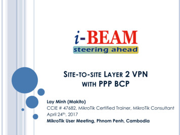
CONFIGURATION – PPP BCPBRANCHES (STEP 4) Create L2TP Client Interfacewith Multi-Link PPP, connectto L2TP Server in HQ: PPP [ ] L2TP ClientMRRU: 1600Connect To HQ’s Public IPUser and Password areName and Password of PPPSecret in VPN ServerProfile: SITE-TO-SITE-L2VPNFill in IPsec Secret if youwant to have encryption onthe link
QUESTIONS & ANSWERSIf you have any questions, please feel free to ask!
THE ENDTHANKS FOR YOUR ATTENTION!Contact Memakito.ogawa@gmail.comSkype: akn makitoViber: 85511277300
VPN TYPES Remote Access For individual employee to access company's resources from home or remote locations VPN Server is usually VPN router at office VPN Client is usually employee's PC/laptop at home Site-to-site For sharing company's resources by connecting: Head Quarter to Branch Office Office 1 to Office 2 etc. VPN Server is usually VPN Hub router at Head Quarter