Transcription
Pub. # 890049-04-00Sept.2020Quick Start GuideRSi “SW” Series VFDUsing the 7-segment (4 digit LED) Keypad/DisplayContents1.Display and Keypad Buttons - Operation . 22.Wiring . 3A.Power Terminals . 3B.Control Terminals . 43.Quick Start Parameters . 5A.Cmd Source (Start/Stop). 5B.Freq Ref Src (Speed Reference) . 5C.Motor Parameters . 5D.Protection Parameters . 54.Parameter Setting - Example “Frequency Reference (Cmd Freq)” . 65.Control and Speed Reference Settings - Detail . 76.Faults and Warnings . 8A.Voltage and Current Faults . 8B.Drive Faults . 9C.External Input Faults. 9D.Communication Faults . 9E.Warnings. 10This guide contains basic parameter settings for control and protection of a standardinduction motor when using the 7-segment (4 digit LED) keypad that comes mounted onthe drive. The default settings are used for a standard induction motor controlled with alinear (fixed) V/Hz. pattern with a base frequency of 60 Hz.Software 12.89 (Benshaw)Page 1 of 10
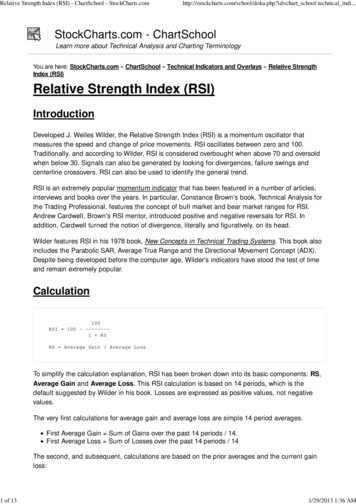
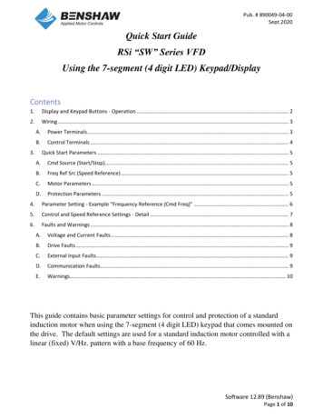
Pub. # 890049-04-00Sept.20201. Display and Keypad Buttons - OperationNo.❶Name7-Segment (LED)Display❷SET Indicator❸RUN Indicator❹❺FWD IndicatorREV IndicatorPushbutton,,DescriptionDisplays running speed (Hz. default), operational status,parameters (codes), parameter choices and Fault Codes.LED turns on (steady) when in program (set) mode (see ENTbutton).Flashes when the ESC key operates as the multi-function key.LED turns on (steady) during running. Flashes during speedchanges (acceleration and deceleration).LED turns on during forward operation.LED turns on during reverse operation.Name[RUN] buttonDescriptionPress to start/run the inverter when set to Keypad control.STOP: Stops the inverter when set to Keypad control.[STOP/RESET]Note: When using remote keypad (LCD), the Stop button is notactive.buttonRESET: Resets the inverter following fault condition.Move between parameters (codes) within a group.[ ] Up button,When in program (set) mode, increase or decrease parameter[ ] Down button values/settings.[ ] Left button[ ] Right button[ENT] button[ESC] buttonMove between parameter groups.Move the cursor when in program (set) mode.Press ENT to enter the program (set) mode of the displayedparameter. After making changes, Press ENT twice to confirmparameter changes.A multi-function button used to configure different functions,such as: Cancellation of a parameter setting Jog operation Local/Remote mode switchingSoftware 12.89 (Benshaw)Page 2 of 10
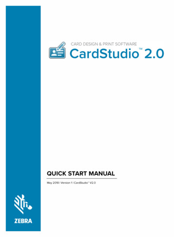
Pub. # 890049-04-00Sept.20202. WiringA. Power Terminals0.5 - 1 HP, (0.4-0.8kW)5.0 - 5.4 HP (3.7 - 4.0kW)2 - 3 HP, (1.5 - 2.2kW)230V, 7.5 - 20 HP (5.5–15kW)460V, 7.5 HP - 30 HP (5.5 - 22kW)Terminal LabelsR(L1)/S(L2)/T(L3)*Use R(L1) and T(L3) forsingle phase power.P1( )/N(-)P1( )/P2( )P2( )/BU/V/WNameDescriptionAC Power InputTerminalsAC Supply Power ConnectionsDC Bus TerminalsDC Reactor TerminalsBrake Resistor TerminalsMotor Output TerminalsDC Voltage TerminalsDC Reactor Wiring Connection (When using aDC reactor, the shorting bar must be removed.)Brake Resistor Wiring Connection3-Phase Induction Motor Wiring ConnectionsSoftware 12.89 (Benshaw)Page 3 of 10
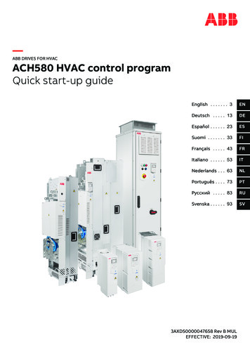
Pub. # 890049-04-00Sept.2020B. Control TerminalsSoftware 12.89 (Benshaw)Page 4 of 10
Pub. # 890049-04-00Sept.20203. Quick Start ParametersA. Cmd Source(Start/Stop)B. Freq Ref Src (SpeedReference)C. Motor ParametersABCSettingsOption #Desc.FunctionGroupParameterRangeDefault0KeypadCmd SourceOperations1Fx/Rx-1drv0: Keypad2Fx/Rx-2(Control-Start/Stop(Main)3Int 4850Keypad-11Keypad-2Freq Ref SrcOperations2V1Frq0: Keypad-14V2(Speed Reference)(Main)5I26Int 485Motor ParametersLoad Duty(Normal/Heavy)Pr04Motor Capacitydr14D. ProtectionParametersPole NumberRated SlipRated Curr(Motor FLA)111213Noload CurrMotor VoltNormal Duty1: Heavy DutyHeavy Duty0.3 HP0.5 HP1.0 HP1.5 HP2.0 HP3.0 HP4.0 HPVaries with5.0 HPDriveRating5.5 HP7.5 HP10 HP15 HP20 HP25 HP30 HP2 480-3000(Rpm)Dependent on1.0-1000.0(A)motor y1664-100(%)Dependent onmotor settingAC Input Volt19170-480(V)240/480Run Prevent(Motor ard Prev 0: NoneReverse PrevProtection Parameters05OL Trip Select(Motor Overload)20OL Trip LevelOL Trip TimeETH Trip Sel(Electronic ThermalMotor Overload)11 Displayed as: 00 as:In-OutPhase Loss Chk(Input/Output PhaseLoss)Pr00Off Off11012On or Cooling41ETH 1 minETH Cont424301201On On Off Off1: Free-Run150601:Free-Run0:Self-cool150115Software 12.89 (Benshaw)Page 5 of 10
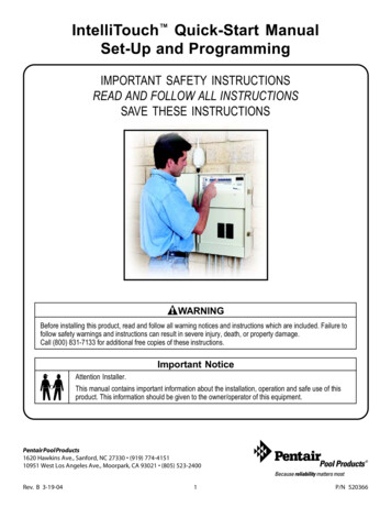
Pub. # 890049-04-00Sept.20204. Parameter Setting - Example “Frequency Reference (Cmd Freq)”After entering the Quick Start parameters, when Frq (Freq Ref Src) is set to Keypad-1 (default), press the ESCbutton to return to the main display in the Operations Group. Program the running speed (Hz.) per the belowtable.Software 12.89 (Benshaw)Page 6 of 10
Pub. # 890049-04-00Sept.20205. Control and Speed Reference Settings - DetailHand - Off - AutoLocal - Off - In.6715Setting2nd V1V2I2Hand Mode-Command Sourcedrv-Speed ReferenceFrqAuto Mode--Cmd Aux (2nd) sourcebA.01Frq Aux (2nd) sourcebA.02With P3 Input Open - VFD uses drv and Frq setingsWith P3 Input Closed - VFD uses bA.01 and bA.02 settingsSoftware 12.89 (Benshaw)Page 7 of 10
Pub. # 890049-04-00Sept.20206. Faults and WarningsThere are 3 levels of Fault conditions in addition to Warning messages. Non-Latched Faults: Do not require a Reset. When the fault is corrected, the fault or warning messagedisappears. The fault is not saved in the fault history.Latched Faults: Require a reset (keypad or external). When the fault is corrected and reset, the faultdisappears. The fault is saved in the fault history.Fatal: Drive requires power to be cycled Off then On.Faults are stored and can be viewed at Pr.91 through Pr.95. When more than 1 fault occurs at the same time,the keypad displays the higher priority fault. Warnings: To be displayed, all warning messages have to enabled with the associated parameters,except IOLW (Inverter Overload Warning). The most recent warning message can be viewed at Pr.90.A. Voltage and Current Motor Overload. Motor current exceeds the set overload levels. Activated whenPr.20 is set to 1 or 2 and the output current has exceeded the Pr.21 level (%) forlonger than the Pr.22 time (seces.).Motor Underload. Motor current is less than the set underload levels. Activatedwhen Pr.27 is set to 1 or 2 and the output current is lower than the Pr.30 level (%)for longer than the Pr.28 time (secs.). Active when the motor speed above twicethe motor slip speed (freq.) bA.12.Pr.04, bA.13, Pr.20,Pr.21, Pr.22OLtOver LoadLatchULtUnder LoadLatchOCtOver Current1 LatchInverter Over Current-1. Output current exceeded 200% of the rated current.-OC2Over Current2 LatchInverter Over Current-2. Excessive output current indicating a short circuitcondition.-OutOver Voltage LatchOver Voltage. Internal DC bus voltage exceeded the trip level.-LutLow VoltageLu2NonLatchedbA.13, Pr.27, Pr.28,Pr.29, Pr.30Low Voltage. Internal DC bus voltage is less than the trip level.bA.19, Pr.81Low Voltage2 LatchLow Voltage-2. Internal DC bus voltage is less than the trip level.bA.19, Pr.82GFtGround Trip* LatchGround Fault. Ground current exceeds a fixed value, varies with invertercapacity ( 30% for 30 msecs.).EtHE-ThermalElectronic Thermal Overload. Inverter has predicted a rise in motor temperature.Activated when Pr.40 is set to 1 or 2 and the output current has exceeded thePr.42 or Pr.43 levels (%). Common Fault during low speed ( 20 Hz.) operation.bA.13, Pr.40, Pr.41,Pr.42, Pr.43Output Phase Open. Current in one or more phases is less than 15% of inverterrated current. Activated when Pr.05 is set to 01.Pr.05Input Phase Open. DC Bus ripple voltage is higher than normal indicating amissing input phase. Activated when Pr.05 is set to 10.Pr.05, Pr.06Inverter Overload. Output current has exceeded the Inverter rated current.Overload ratings for the inverter are 150% for 1 min and 200% for 4 sec.-LatchIPOOutput PhaseLatchOpenInput PhaseLatchOpenIOLInverter OLTnMtNo Motor Trip LatchPOtLatchLow Current Fault .Activated when Pr.31 is set to 1 and the output current isbelow the Pr.32 level (%) for the Pr.33.time (secs.).-bA.13, Pr.31, Pr.32,Pr.33* Ground Fault monitoring is not supported inverters 5.0 HP and lower. An over voltage Fault (ovt) or over current Fault (OCT) will occur.Software 12.89 (Benshaw)Page 8 of 10
Pub. # 890049-04-00Sept.2020B. Drive FaultsDisplayOHtFaultOver HeatTypeLatchHWtH/W-DiagTripFatalFAnFan TripLatchRelatedParametersDescriptionInverter Over Heat. Inverter heat sink temperature exceeded 110 C.-Hardware diagnostic Fault. Error detected in the Inverter Control Board. Areasmonitored are memory (EEPRom), analog-digital converter output (ADC Off Set),or CPU watchdog (Watch Dog-1, Watch Dog-2).EEP Err: An error occurred in reading/writing parameters due to keypad ormemory (EEPRom) Fault.ADC Off Set: An error in the current sensing circuit (U/V/W terminal, currentsensor, etc.).Cooling Fan Fault. Inverter detected an issue with the cooloig fan. ActiavtedPr.79when Pr.79 is set to 0 (zero).-C. External Input ionIn.65 - In.69External TripInverterOutputdisabled(blocked)LatchExternal Fault. Input signal at terminal Px set to (4) External Trip is activated.NonLatchedBX Fault, Inverter Disabled. Input signal at terminal Px set to (5) BX is activated. In.65 - In.69ntCNTC OpenLatchPidPre-PID FailLatchxbrExt-BrakeLatchSafety A(B)ErrLatchbxSFA/SFbInternal Temperature Sensor Fault. Temperature sensor of the Insulated GateBipolar Transistor (IGBT) is open or sensing below 10 C.In Pre-PID mode, PID feedback is measured below the AP.35 level (%) for longerAP.34, AP.35, AP.36than the AP.36 Pre-PID time (secs.).When using External Brake Control, the Inverter output starting current remainedAd.41, Ad.42below the value set at Ad.41, Brake Open Current.Safe Torque Off Fault. One of the two safety (STO) input terminlas (SA, SB, SC)is open.-D. Communication FaultsDisplayLOrFaultLostCommand orReferenceTypeNonLatchedIOtIO Board Trip LatchErrCPArParaWriteTripOPtOption Trip-1 LatchLatchRelatedParametersDescriptionLost Command Source (Start/Stop control): Lost command over communcations(RS-485 and other network options).Pr.12, Pr.13, Pr.14,Lost Frequency Reference Source (Speed control): Lost speed reference viaPr.15analog or communications.Conbtrol board (I/O board) or external communication card is not connected tothe inverter.Displayed when the error code continues for more than 5 sec. Displayed as:(‘Errc’ - ’-rrc’ - E-rc’ - ’Er-c’ - ‘Err-‘ - ’- -rc’ - ‘Er- -‘ - ’- - - -‘- ’Errc’ - )Parameter Writing Error when using remote display (LCD). Displayed whencommunication fails during parameter writing due to a control cable Fault or a badconnection.Option Board Fault. Error is detected between the inverter and thecommunication board.--Software 12.89 (Benshaw)Page 9 of 10
Pub. # 890049-04-00Sept.2020E. tionMotor Overload Warning. Activated when Pr.17 (overload warning) is set to 1and the motor current is above the Pr.18 level (%) for longer than the Pr.19 time(secs.). One of the digital output terminals (Relay 1 or Q1) can be set to 5 (OverLoad) to output the warning.Motor Underload Warning. Activated when Pr.25 is set to 1 and the outputcurrent is lower than the Pr.30 level (%) for longer than the Pr.26 time (secs.).One of the digital output terminals (Relay 1 or Q1) can be set to 7 (Under Load) tooutput the warning.Inverter Overload Warning. Displayed after 36 secs. of a 150% overload. Oneof the digital output terminals (Relay 1 or Q1) can be set to 6 (IOL) to output thewarning.Lost Command Warning: Lost RS-485 communications at the terminal block(Start/Stop or Speed Reference) or lost analog speed reference based on theconditions set at Pr.13- 15. Warning occurs even with Pr.12 set to 0. Applies toboth Start/Stop control (when over communications) and Speed Reference viaanalog or communications. One of the digital output terminals (Relay 1 or Q1) canbe set to 13 (Lost Command) to output the warning.Cooling Fan Warning. Activated when Pr.79 is set to 1. One of the digital outputterminals (Relay 1 or Q1) can be set to 8 (Fan Warning) to output the warning.Pr.04, Pr.17, Pr.18,Pr.19, OUT.31,OUT.33OLWOver LoadWarningULWUnder LoadWarningIOLWINV OverLoadWarningLCWLostCommand orReferenceWarningFAnWFan WarningWarningDB Warn%EDWarningDynamic Brake Warning. DB resistor usage rate exceeds the set percentage.Pr.66Retry Tr Tune WarningSensorless Auto Tuning warning. The warning occurs when the motor’s rotortime constant (Tr) is either too low or too high.DRV.09, bA.20dbWtrtrbA.13, Pr.04, Pr.25,Pr.26, OUT.31,OUT.33OUT.31, OUT.33Pr.12, Pr.13, Pr.14,Pr.15Pr.79, OUT.31,OUT.33Software 12.89 (Benshaw)Page 10 of 10
RSi "SW" Series VFD Using the 7-segment (4 digit LED) Keypad/Display Contents . VFD uses drv and Frq setings. Software 12.89 (Benshaw) Page 8 of 10 Pub. # 890049-04-00 Sept.2020 6. Faults and Warnings There are 3 levels of Fault conditions in addition to Warning messages.