Transcription
An InformationTechnology ManagementReference ArchitectureImplementationDesigned for the Sun Internet Data Center Mail andMessaging Reference ArchitectureBy Edward Wustenhoffhttp://www.sun.com/blueprintsSun Microsystems, Inc.4150 Network CircleSanta Clara, CA 95045 USA650 960-1300Part No. 816-6725-10Revision A
Copyright 2002 Sun Microsystems, Inc., 4150 Network Circle, Santa Clara, California, U.S.A. All rights reserved.This product or document is protected by copyright and distributed under licenses restricting its use, copying, distribution, and decompilation.No part of this product or document may be reproduced in any form by any means without prior written authorization of Sun and its licensors,if any. Third-party software, including font technology, is copyrighted and licensed from Sun suppliers.Sun, Sun Microsystems, the Sun logo, Sun BluePrints, Sun Enterprise, Sun Fire, Sun Management Center,Sun ONE, Sun StorEdge, SunProfessional Services, Sun Ray, Authorized iForce , Java, Netra and Solaris are service marks, trademarks, or registered trademarks of SunMicrosystems, Inc. in the United States and other countries.The OPEN LOOK and Sun Graphical User Interface was developed by Sun Microsystems, Inc. for its users and licensees. Sun acknowledgesthe pioneering efforts of Xerox in researching and developing the concept of visual or graphical user interfaces for the computer industry. Sunholds a non-exclusive license from Xerox to the Xerox Graphical User Interface, which license also covers Sun’s licensees who implement OPENLOOK GUIs and otherwise comply with Sun’s written license agreements.RESTRICTED RIGHTS: Use, duplication, or disclosure by the U.S. Government is subject to restrictions of FAR 52.227-14(g)(2)(6/87) andFAR 52.227-19(6/87), or DFAR 252.227-7015(b)(6/95) and DFAR 227.7202-3(a).DOCUMENTATION IS PROVIDED "AS IS" AND ALL EXPRESS OR IMPLIED CONDITIONS, REPRESENTATIONS AND WARRANTIES, INCLUDINGANY IMPLIED WARRANTY OF MERCHANTABILITY, FITNESS FOR A PARTICULAR PURPOSE OR NON-INFRINGEMENT, ARE DISCLAIMED,EXCEPT TO THE EXTENT THAT SUCH DISCLAIMERS ARE HELD TO BE LEGALLY INVALID.Copyright 2002 Sun Microsystems, Inc., 4150 Network Circle, Santa Clara, California, Etats-Unis. Tous droits réservés.Ce produit ou document est protégé par un copyright et distribué avec des licences qui en restreignent l’utilisation, la copie, la distribution, et ladécompilation. Aucune partie de ce produit ou document ne peut être reproduite sous aucune forme, par quelque moyen que ce soit, sansl’autorisation préalable et écrite de Sun et de ses bailleurs de licence, s’il y en a. Le logiciel détenu par des tiers, et qui comprend la technologierelative aux polices de caractères, est protégé par un copyright et licencié par des fournisseurs de Sun.Des parties de ce produit pourront être dérivées des systèmes Berkeley BSD licenciés par l’Université de Californie. UNIX est une marquedéposée aux Etats-Unis et dans d’autres pays et licenciée exclusivement par X/Open Company, Ltd.Sun, Sun Microsystems, the Sun logo, Sun BluePrints, Sun Enterprise, Sun Fire, Sun Management Center, Sun ONE, Sun StorEdge,SunProfessional Services, Sun Ray, Authorized iForce, J ava, Netra et Solaris sont des met arques de fabrique ou des marques déposées, oumarques de service, de Sun Microsystems, Inc. aux Etats-Unis et dans d’autres pays.L’interface d’utilisation graphique OPEN LOOK et Sun a été développée par Sun Microsystems, Inc. pour ses utilisateurs et licenciés. Sunreconnaît les efforts de pionniers de Xerox pour la recherche et le développement du concept des interfaces d’utilisation visuelle ou graphiquepour l’industrie de l’informatique. Sun détient une licence non exclusive de Xerox sur l’interface d’utilisation graphique Xerox, cette licencecouvrant également les licenciés de Sun qui mettent en place l’interface d’utilisation graphique OPEN LOOK et qui en outre se conforment auxlicences écrites de Sun.CETTE PUBLICATION EST FOURNIE "EN L’ETAT" ET AUCUNE GARANTIE, EXPRESSE OU IMPLICITE, N’EST ACCORDEE, Y COMPRISDES GARANTIES CONCERNANT LA VALEUR MARCHANDE, L’APTITUDE DE LA PUBLICATION A REPONDRE A UNE UTILISATIONPARTICULIERE, OU LE FAIT QU’ELLE NE SOIT PAS CONTREFAISANTE DE PRODUIT DE TIERS. CE DENI DE GARANTIE NES’APPLIQUERAIT PAS, DANS LA MESURE OU IL SERAIT TENU JURIDIQUEMENT NUL ET NON AVENU.PleaseRecycle
An Information TechnologyManagement ReferenceArchitecture ImplementationThis article is the fifth in a series of articles by Edward Wustenhoff on the data centermanagement infrastructure. The focus of this article is on the implementation of themanagement infrastructure.It is a follow-up article on the “An information Technology Management ReferenceArchitecture” article published earlier by Edward Wustenhoff and the SunBluePrints group. It describes the implementation of IT management referencearchitecture in the Authorized iForceSM Ready Center (iFRC) program that displaysan IDC Mail and Messaging Architecture. The iFRC program is a Sun program thatprovides reference implementations and proof of concepts to assist our customers inavoiding common pitfalls.This article describes the technical aspects and details of the management andorganization (M&O) architecture deployment. Conceptually, the IDC Mail andMessaging Reference Architecture implementation consists of two majorcomponents. The first component of the implementation is the Message Server(Sun ONE) that represents the mission-critical business application. The secondmajor component of this implementation is the systems management tools that areimplemented to monitor, maintain, and report on availability and SLA adherence ofthe business application. This is the M&O architecture.This article describes the implementation of these tools and their interactions, anddiscusses how they are combined into a systems management and Service LevelAgreement (SLA) reporting solution. This article provides topological views of themanagement implementation, individual tool implementations, combined toolsimplementations, and details of the essential integration points between the tools.1
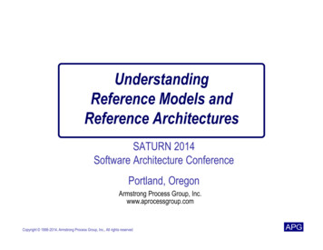
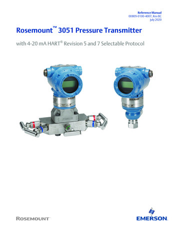
LimitationsThis article does not describe the people and process aspects of IT management.Further, this article is not intended to be a detailed implementation reference. It is tobe viewed as a proof of concept, showing the structure and essential functionality tobe addressed in an M&O architecture. Also, the M&O architecture is not designedwith a focus on availability and performance.System TopologyFIGURE 1 shows the implementation of the M&O architecture. Note how thehierarchy matches the management architecture that was discussed in “Concepts, ITManagement Framework” in the previous article. Also, note that the actualimplementation does not include anything outside the box that indicates the ITinfrastructure management framework.FIGURE 2 presents the basic topology of the actual system environment. This diagramis organized so that there is a distinction between the managed systems and thesystems that are to perform the systems management function.Note that the systems pictures do not represent the actual system types that weredeployed. All of the management systems were Netra X1 servers.2An Information Technology Management Reference Architecture Implementation July 2002
Infrastructure management frameworkAgentEmail Phone ss-1 process-2YaamguestAgentManagementconsole- Business application health- Application infrastructure health- System and storage health- Network healthFIGURE 1SupportFrameworkconsoleIT Management ArchitectureNotice in FIGURE 2 that individual systems are implemented to support the servercomponents of the management tools being implemented. This particularconfiguration was chosen primarily for logistical reasons and would not likely bepractical in a production environment. The exact layout of an implementation isdetermined by many factors including size of machine, speed of networkconnections, port conflicts between products, and limiting the impact of outages.With this basic system configuration established, the following sections detail theimplementation of the systems management tool set used in the iFRC program andthe manner in which they are interfaced to each other. The final section in this articledescribes the combined tools implementation in order to present a comprehensiveview of the environment.System Topology3
ps02DirectoryservicessunmcManaged systemsMail transferagentsManagement earraysdeladminmmp01CoremailFoundrynetwork serversteamqMailmultiplexersncimpFIGURE 2iFRC Management Configuration of the IDC Mail and Messaging ReferenceArchitecture DeploymentTools SelectionReferring to the requirements described in the previous article, the followingproducts were deployed to facilitate the different views. 4MicroMuse Netcool provides the NOC view that shows all alerts in allcomponents. These components have their own views:An Information Technology Management Reference Architecture Implementation July 2002
MicroMuse ISM provides the SLA view that reports the status of themessaging application against a predefined .MicroMuse Netcool and ISM provides the applications infrastructure SLAview that reports on the status of the software components that support theapplication. Lightweight Directory Access Protocol (LDAP), Network TimeProtocol (NTP) and domain name service (DNS) are included in this. Sun Management Center (SunMC) software is the core of the systemadministration view that reports on the status and supports the administration ofall Sun computer and storage systems. TeamQuest is responsible for the performance view that monitors the status ofthe system and networks as far as they relate to being able to handle theprocessing load. Foundry’s Ironview with MicroMuse’s Netcool provide the network view thatreports on network alerts and supports the administration of the networkcomponents.Using the same organization as described in “Implementation Requirements,Management at All Layers” of the previous article, TABLE 1 summarizes the managedaspects per tool by layer.TABLE 1Tools Distribution by LayerLayeriForce rityBusinessapplicationMessage Server 5.1(Sun Micro-MuseTBDTBDTeamQuestMicromuseTBDDirectory Server 4.13(Sun TBDNetra T1 serverSunMCSunMCTBDTeamQuestTBDNetra 1405 serverSunMCSunMCTBDTeamQuestTBDSun Fire 6800 uctureComputing andstorageplatformTools Selection5
TABLE eTools Distribution by LayeriForce rityNetra X1 serverSunMCSunMCTBDTeamQuestTBDSun StorEdge T3arraySunMCSunMCTBDTeamQuestTBDSun Enterprise A1000 hardwareSunMCN/ATBDTeamQuestTBDSun SAN switchesSunMCTBDTBDTeamQuestTBDSun Cluster 3.0softwareSunMCSunMCTBDTeamQuestTBDSolaris OperatingEnvironment (SolarisOE)SunMCSunMCTBDTeamQuestTBDFoundry NetIronFoundryFoundryTBDTeamQuestTBDFoundry ServerIronFoundryFoundryTBDTeamQuestTBDFoundry BigIronFoundryFoundryTBDTeamQuestTBDiForce LabN/AN/AN/AN/AN/ATools Implementation DetailsThe following sections describe the details of the tools implemetation.IronViewThe IronView product set monitors and manages the networking equipment fromFoundry Networks. IronView provides a console for direct access to the networktopology. Its main function is the administration of the network topology. It wasimplemented on the deladmin server.The Foundry Network devices issue SNMP traps directly to Netcool for the NetworkOperations Center (NOC) and SLA processing. In this implementation, IronView isinstalled co-resident with the Message Server (Sun ONE) delegated administratorservices because the IronView processing requirements are very low.6An Information Technology Management Reference Architecture Implementation July 2002
Sun Management Center 3.0The SunMC 3.0 software is an element manager that details and monitors theoperation of Sun servers, peripherals, and applications. In the context of the iFRCprogram, SunMC is used primarily to provide low-level monitoring of theapplication servers to report on hardware and operating system stresses and faults.Loren Pearce from SunPS collected and described the following details on SunManagement Center 3.0.SunMC 3.0 has a three-tier architecture. The first tier includes the “agents” thatcollect information and alerts from the individual systems being monitored. Thesecond tier is a server component that collects information from the monitoringagents and reports this information to the clients. This tier also provides automationcapabilities.The third tier is the client tier that is usually provided by the server, console, and anagent component all executing on one system. Additional agents are deployed to theapplication servers for monitoring of these systems. The console is viewed usingSun Ray appliance displays. While this is not unusual, it is not necessary tocombine the three components of SunMC 3.0 on one system.In addition to monitoring and reporting on the application servers, SunMC 3.0agents are deployed on the systems management servers in order to monitor theiroperation and alert the systems administrator to any problems within themonitoring complex.Tools Implementation Details7
Managed s01idam02idaps02SunMC agent monitoringManagement ha02NotDirectlymonitored monitoreddevices by SunMCdeladminmmp01FIGURE 3SunMC 3.0 ConfigurationTABLE 2 details how the various components of SunMC 3.0 are distributedthroughout the system topology.TABLE 28SunMC 3.0 Component DistributionComponentSystemPort(s)NotesSunMC serversunmc1621631641651661671682099SunMC consolesunmcVariableSunMC agentAn Information Technology Management Reference Architecture Implementation July 2002
TABLE 2SunMC 3.0 Component MC agent replacesstandard snmp 161ldapm01161ldapm02161mmp01–mmp06161The Netcool SunMC probe collects alerts for reporting to the NOC and the SLAmanager. This probe acts as a client to SunMC to capture the system level events andforwards them to the Netcool database.SunMC also provides investigation and alert management through its console. Theconsole is made available as part of the system administration view so that a systemoperator can obtain additional details pertaining to outages detected in theenvironment. With this information, the system administrator can determine thecorrect course of action for resolving the operational impact.TeamQuestTeamQuest performance software monitors the performance metrics of theenvironment against the best practices as defined in the Sun Professional Services SM(SunPS) program performance tuning and capacity planning methodology, outlinedin the “Implementation Requirements” section of the previous article. Whenperformance target violations are detected, alerts are sent to Netcool in the form ofSNMP traps that are then processed and forwarded to the NOC and SLA views.Tools Implementation Details9
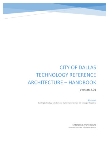
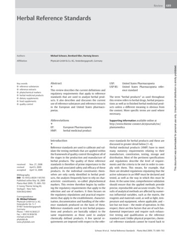
TeamQuest also provides capacity planning and performance tuning capabilities.This section describes the details of how the iFRC implemented certain aspects ofperformance management. It was provided by Scott Johnson, Senior Engineer andJoe Rich, Manager Corporate Technical Relations, from TeamQuest Corporation, whoprovided the technical expertise and tools.TeamQuest View and TeamQuest Model were the two products used in the iFRC toprovide a mechanism to capture and report on the performance and capacity of thesystems in the architecture.TeamQuest View is a comprehensive, analytical tool that reports system performanceand helps locate bottlenecks. Performance data is collected from several differentsources on the system and stored into a local database for real-time or historicalanalysis.TeamQuest Model provides predictive analysis required for long-term capacityplanning. This tool, using data retrieved from the architecture systems, was used tobuild models of the systems and applications. These models were validated againstthe benchmark data and were used to experiment with “what-if” questions relatingto the number of users and the effects of equipment changes.TeamQuest ViewTeamQuest View consists of a server-based component (framework) that isresponsible for (among other things) performance data collection and storage andthreshold violation notification. TeamQuest View also has a Motif-based client GUI(TQView) which, when connected over TCP/IP to the server component, producesgraphical displays of both real-time and historical performance data. In the iFRC, theclient GUI with associated reports is located on a separate server with automaticlogin capability from any one of several management stations connected to a SunRayserver. Upon login, TQView automatically establishes a connection to the desiredarchitecture server and produces a series of predefined performance reports(operational views). The reports consist of a number of statistics that were selectedfrom baseline performance monitoring metrics as defined in the SunPS performancetuning and capacity planning methodology. FIGURE 4 is one example, showingimportant CPU metrics, the top 10 busiest disks, the number of RPC client calls persecond and the buffer read and write cache hit percentages. In addition to thesereports, TeamQuest provides a large number of pre-defined reports and alsosupports ad hoc report generation.10An Information Technology Management Reference Architecture Implementation July 2002
FIGURE 4Operational View Example of the Message Server (Sun ONE) from TeamQuestViewThreshold Violation Detection and NotificationThe TeamQuest Framework component samples data at a preset interval and storesthat data into its performance database. default sampling rate of one minute isimplemented. As the data is collected, TeamQuest automatically checks the values ofthe statistics against any defined threshold levels. A set of thresholds, based onbaseline performance monitoring metrics as defined in the SunPS performancetuning and capacity planning methodology, was established for all of the servers inthe architecture.When a threshold criterion is met, an alert is issued. The default action is to log theevent into the performance database in the alarm log. In addition, the iFRC teamchose to send all alerts through an SNMP trap to the MicroMuse Netcool Omnibusconsole. MicroMuse assisted in the integration of the TeamQuest View client as atool under Netcool so that it could be launched in context to the server that issuedthe alert. In this way, a report showing a graph of the statistic in violation canautomatically be generated. FIGURE 5 and FIGURE 6 show drilling down from an alertevent sent to Netcool to the statistic in violation on the server under stress.Tools Implementation Details11
FIGURE 512MicroMuse/TeamQuest View IntegrationAn Information Technology Management Reference Architecture Implementation July 2002
FIGURE 6TeamQuest View Report as a Result of the “Start in Context” by MicroMuseApplication Level Resource ReportingWhen monitoring, tuning, and predicting capacity of systems, identifying the criticalapplications (or workloads) of the system is imperative. SLAs are usually created forthese critical applications, and thus dictate which workloads must be monitored.TeamQuest provides a mechanism, through identification of the processes thatcomprise an application, to track the resource consumption of that group ofprocesses. Through a definitional language, the user builds process groups that arecalled workloads.For the IDC Mail and Messaging Architecture, a common set of workload definitionsis created and loaded into the TeamQuest performance database on each system.Tools Implementation Details13
Note – To enhance the data collection, Solaris OE process accounting was enabledon all of the systems. Thus when a sample was taken, both the running processactivity and the completed process activity was merged to provide the best captureratio.Note – TeamQuest reduction processing was deactivated so that each and everyprocess captured was recorded into the performance database.As TeamQuest process-level data was collected, it was compared to the workloaddefinitions and deposited into the appropriate workload container. This allowed theiFRC team to do several very important functions: Monitor (and alert on) the resource consumption by workload. Provide the basic operational entities for the capacity planning exercisesdescribed later. In addition to the prestored workload definitions, TeamQuest hasthe capability to reprocess the raw process data after the fact into workloads, thusallowing for “tuning” and further refinement of the workloads. TABLE 3 lists theworkloads and their definitions for the MAIL servers.TABLE 3Sample and Workload DefinitionsWorkload es associated with TeamQuestPerformance software or SunMCmonitoring agentsProcesses associated with Sun ClusterMessage store maintenance program(deadlock checks, message deletion, andso forth)Processes that handle POP3 messagesto/from MMP serverscommand /tq.*/ orcommand esdcommand popd andlogin mailsrvProcesses that handle IMAP4 messagesto/from MMP serverscommand imapd andlogin mailsrvProcesses that handle the MTA queuefor (SMTP) messageslogin mailsrv and((command tcp smtp server) or(command ims master))login mailsrvClusterStoredPost OfficeProtocol(POP)(InternetMail AccessProtocol(IMAP)Simple MailTransferProtocol(SMTP)OtherMessageServer (SunONE)Other14Any other processes associated with theMessage Server (Sun ONE) applicationfullcmd /.*cluster.*/command stored andlogin mailsrvAny processes not explicitly included inthe preceding workloadsAn Information Technology Management Reference Architecture Implementation July 2002
FIGURE 7 is a screen display of one of the mail servers showing the overall CPUutilization along with the same utilization broken out by course applicationworkloads and finally by a finer granularity set of workloads. It is easy to see howmuch of the resource each application is consuming and, within the Message Server5.1 (Sun ONE) application, which specific mail protocol is using the most resources(POP).FIGURE 7Overall CPU Utilization By WorkloadCapacity PlanningAs mentioned earlier, TeamQuest Model is the capacity planning tool that was usedin this study. TeamQuest Model applies operational analysis principles to measuredcomputer system performance data to build baseline performance models. You canthen modify the baseline models to predict system performance when configurationsand/or workloads change.Tools Implementation Details15
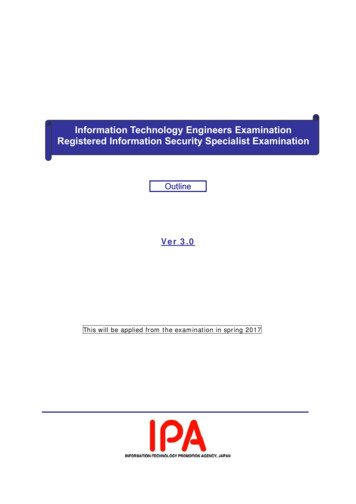
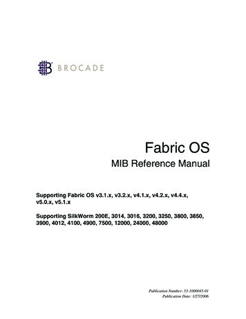
The models are known as queuing network models (QNMs). A QNM consists of a setof resources (CPU, disks, terminals, and so forth) that can be visited by customersfrom one or more workloads. Workloads can have unique intensities (arrival rates orpopulations), priorities, and average service demands (visits and service times pervisit) at resources. Solving a QNM produces estimates of throughputs, responsetimes, queue lengths, and utilizations for each workload at each resource, as well asestimates of overall workload throughputs and response times.Results are presented in spreadsheet like displays and charts. For example,components of response time charts allow performance analysts to quickly assessimpacts of queuing delays at resources on workload response times.TeamQuest Model provides two methods to solve QNMs—approximate mean valueanalysis (MVA) and simulation. Approximate MVA is normally used, since it ismuch faster than simulation. Approximate MVA iterates solving for response times,throughputs and queue lengths until convergence occurs for all workloads at allresources. Approximate MVA is the method that was used to model the messagingIDC reference architecture systems.Baseline models of several representative benchmarks were created, including anenterprise model, built by including a representative system from each server classin the messaging system.Since actual transaction completion rates were not available for the user activity, asynthetic transaction rate was constructed based on the email sender test profile andthe number of users. FIGURE 8 shows the throughput of the two major workloads forthe enterprise. The throughput rate is the transactions per second based on thesynthetic transaction definition discussed previously.16An Information Technology Management Reference Architecture Implementation July 2002
4540Transaction rate3530252015105014,0009,00024,000 34,000 44,000 54,000 64,000 74,000 84,000 94,00014,000 19,000 24,000 29,000 34,000 39,000 44,000 49,000UsersPOPFIGURE 8SMTPMajor Workload ThroughputThe SMTP workload throughput increases as the number of email senders increases.However, the throughput for the POP workload increases steadily only to the 54000/29000 user level and reaches a plateau by the 64000/34000 user level. This indicatesthat something is constraining the activity of the POP workload.Further analysis indicates that the constraint occurred in the MMP server. FIGURE 9shows that the CPU for mmp01 is about 95 percent utilized and is most likely theconstraining factor.Tools Implementation Details17
10090Percent used8070605040302010014,0009,00034,000 54,000 74,000 94,000 114,000 134,000 154,000 174,000 194.00019,000 29,000 39,000 49,000 59,000 69,000 79,000 89,000 99,000Usersmmp01 CPUFIGURE 9c1t0d0mmp01 controller1mmp01 controller0mmp01 c0t0d0Five Most Active Resources for System mmp01In the benchmark, the configuration consisted of six MMP servers, which wouldappear to be able to support about 8000 email readers. The models suggest that tosupport the 94,000 email reader level would require 12 Netra T1 systems.Since TeamQuest Model allows you to play “what-if” scenarios both on populationgrowth and on configuration changes, you can see the results of the same workloadrun on a two-CPU or a four-CPU Netra t1405. (The relative performancecharacteristics of the CPUs were provided by SunPS).With the MMP servers upgraded to a two-CPU Netra t1405, the enterprise is able toadequately process the work. FIGURE 10 shows the throughput for both the POP andSMTP workloads steadily increasing as the number of users increases.18An Information Technology Management Reference Architecture Implementation July 2002
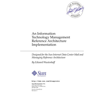
4540Transaction rate3530252015105014,0009,00024,000 34,000 44,000 54,000 64,000 74,000 84,000 94,00014,000 19,000 24,000 29,000 34,000 39,000 44,000 49,000UsersPOPFIGURE 10SMTPPOP and SMTP Throughputs on MMP Servers as Two-CPU Netra t1405ServersThe active resource utilization for each system indicates that there are not anybottlenecks in any of the systems (MMP – 8 percent, messaging – 39 percent, MTA –18 percent). However, if we continue our modeling exercise, and double the numberof active users, the MMP server becomes saturated. Then, increasing the hardwareon the MMP server is necessary. By modeling a number of “what-if” scenarios, wearrive at a four-CPU configuration that adequately supports the doubling of thepopulation. FIGURE 11, FIGURE 12, and FIGURE 13 show the active resource utilizationfor each system type, supporting up to a 194000/99000 user level.Tools Implementation Details19
1009080Percent used70605040302010014,0009,00034,000 54,000 74,000 94,000 114,000 134,000 154,000 174,000 194.00019,000 29,000 39,000 49,000 59,000 69,000 79,000 89,000 99,000Usersmmp01 CPUc1t0d0FIGURE 11mmp01 controller1mmp01 controller0mmp01 c0t0d0mmp01 Active Resource Utilization (4-CPU Netra t1405 Server)10090Percent used8070605040302010014,0009,00034,000 54,000 74,000 94,000 114,000 134,000 154,000 174,000 194.00019,000 29,000 39,000 49,000 59,000 69,000 79,000 89,000 99,000UsersCPUFIGURE 1220controller 1sd50c0t0d0controller 0smtp01 Active Resource Utilization (4-CPU Netra t1405 Server)An Information Technology Management Reference Architecture Implementation July 2002
10090Percent used8070605040302010014,0009,00034,000 54,000 74,000 94,000 114,000 134,000 154,000 174,000 194.00019,000 29,000 39,000 49,000 59,000 69,000 79,000 89,000 99,000Usersha01 CPUFIGURE 13controller 7controller 8controller 3controller 6ha01 Active Resource Utilization (12-CPU Sun Fire 6800 Server)The ha01 system, being one of the message store systems, is handling the maildemands of the increased user population easily.Through the TeamQuest Performance software, the iFRC team could provideaccurate server sizing information based on the various end-user usagerequirements.MicromuseThe Micromuse Netcool product suite is implemented to collect events andinformation from the other system management tools, consolidate this information,assess the impact on the environment, and produce service level reports andinformation against the application set. This is accomplished using the followingMicromuse products Object Server: The Netcool Object Server is an in-memory database that providesevent collection, filter design, and view services. The Object Server provides thefoundation upon which the other products in the Netcool suite operate. In theiFRC configuration, redundant object servers are in
Foundry's Ironview with MicroMuse's Netcool provide the network view that reports on network alerts and supports the administration of the network components. Using the same organization as described in "Implementation Requirements, Management at All Layers" of the previous article, TABLE 1 summarizes the managed aspects per tool by layer.