Transcription
LECTURE NOTESONTELECOMMUNICATION SWITCHINGTHEORY AND APPLICATIONSB.Tech V semester(IARE-R16)Prepared byDr.P.Ashok babu, ProfessorMr.U.Soma naidu, Asst.ProfMr.A.Karthik,Asst.Prof
SyllabusUNIT-IINTRODUCTIONClasses: 10Introduction: Evolution of telecommunications, simple telephone communication, manual switchingsystem, major telecommunication networks, strowger switching system, crossbar switching; ElectronicSpace Division Switching: Stored program control, centralized SPC, distributed SPC, enhanced services,two stage networks, three stage network n-stage networks.UNIT-IITIME DIVISION SWITCHINGClasses: 09Time Division Switching: Time multiplexed space switching, time multiplexed time switching,combination Switching, three stage combination switching, n-stage combination switching; TrafficEngineering: Network traffic load and parameters, grade of servicVe and blocking probability, modelingswitching systems, incoming traffic and service time characterization, blocking models and loss estimates,delay systems.UNIT-IIIDATA NETWORKSClasses: 08Data networks: Block diagram, features, working of EPABX systems, data transmission in PSTNs, datarates in PSTNs, modems, switching techniques for data transmission, circuit switching, store and forwardswitching data communication architecture.ISO-OSI reference model, link to link layers, physical layer, data link layer, network layer, end to endlayers, transport layer, session layer, presentation layer, Satellite based data networks, LAN, metropolitanarea network, fiber optic networks, and data network standards.UNIT-IVTELEPHONE NETWORKSClasses: 08Telephone Networks: Subscriber loop systems, switching hierarchy and routing, transmission plan,transmission systems, numbering plan, charging plan, signaling techniques, in channel signaling, commonchannel signaling, cellular mobile telephony.UNIT-VINTEGRATED SERVICES DIGITAL NETWORKSClasses: 10Integrated Services Digital Networks: Motivation for ISDN, new services, network and protocolarchitecture, transmission channels, user network interface, signaling, numbering and addressing, servicecharacterization, interworking, ISDN standards, broadband ISDN ,voice data Integration.
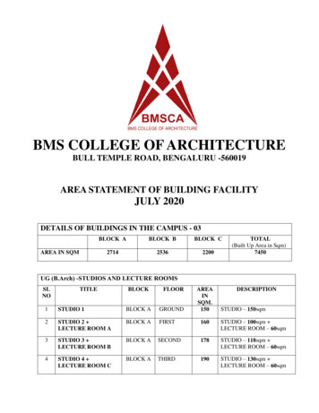
UNIT-ITELECOMMUNICATION SWITCHING SYSTEMAND NETWORKIntroductionThe world has undergone many changes since the evolution of man. For instance, theexchange of information was initially in the form of signs and sounds. This transitioned to thelanguage and script form with advanced inventions. The communication from one place toanother which called for distance between individuals was carried through letters; sent bypigeons and between two groups through drum beats or semaphores. Men used to travel longdistances to pass on messages.Today‘s world is more an age of communication. The advancement of communicationtechniques has increased the speed with which the transfer of information takes place. Thisdevelopment has not been an easy process. At the onset of the invention of communicationsystems, the invention and usage of telephony was the most important one. The way thetelephone systems evolved from a basic system into an essential multi- purpose friendlygadget today, leaves one and all astonished knowing the innovations made out of the meagreresources available in those days.TelecommunicationsThe exchange of information between two or many individuals is called Communication. Theword tele is a Greek word which means distance. Hence, Telecommunication means theexchange of information between two distant places.Telecommunications represent the transfer of information, from an entity at one place to anentity at another place, whereas the information can be in the form of data, voice or symbol.The entities can be human beings, computers, facsimile machines, telegraphy machines,phones or so on. In telephone conversation, the one who initiates the call is referred to as theCalling Subscriber and the one for whom the call is destined is the Called Subscriber. Inother cases of information transfer, the communicating entities are known as Source andDestination, respectively.In March 1876, Alexander Graham Bell invented and demonstrated his telephone set and thepossibility of long distance voice communication. He demonstrated the point-to-pointcommunication, in which a calling subscriber chooses the appropriate link to establishconnection with the called subscriber. This system also requires some mode of Signalling toalert the called subscriber about the incoming call and a signal to indicate the callingsubscriber, when the called subscriber is busy on another call.Need for Switching ExchangesThe point-to-point connection for establishing communication requires the telephone sets to belinked using wires. If the number of telephone sets or the subscribers present is low in number,the type of connection will be a little complex. However, if this number is high or moderate,then the connections will lead to a mess. To understand the complication, let us consider anetwork of 5 subscribers.
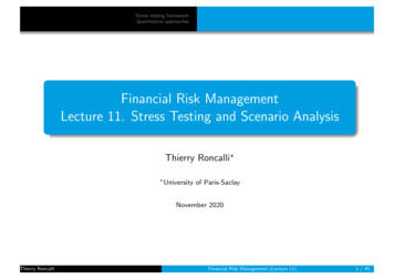
The following illustration shows a point-to-point connection for five subscribers (telephonesets):In the point-to-point connection, for n entities, we need n(n-1)/2 links. All these links form anetwork. Networks with point-to-point links among all the entities are known as FullyConnected Networks. The number of links required in a fully connected network becomesvery large even with moderate values of n.Hence, a system of switching the networks is needed in-between these subscribers.Alexander Graham Bell recommended the Switching between the subscribers using aswitching office that maintains the telephone connections.Switching SystemsThis network connection cannot be simply made with telephone sets and bunch of wires, but agood system is required to make or break a connection. This system is known as the SwitchingSystem or the Switching Office or the Exchange. With the introduction of the switchingsystem, the subscribers instead of getting connected directly to one another, are connected to aswitching office and then to the required subscriber.The following figure will help you understand the switching system
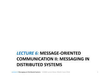
With the introduction of switching systems, the need for traditional connections between thesubscribers reduced. All the subscribers need to have a connection with the switchingsystem, which makes or breaks any connection, requested by the calling subscriber. Theswitching system, which is also called the Telephone Exchange, takes care of establishingthe calls. Hence, the total number of such links is equal to the number of subscribers connectedto the system.The early systems required manual operations to establish telephone calls. An operator usedto receive a call from the calling subscriber and then connect the call to the called subscriber.Later on, the system was automated.Telephone ModelThe following figure will help you understand the model of telephones in the early stage ofits invention.When you see the telephone in the above figure, the dialer part and the microphone areconnected to a stationary wooden plank; and the speaker to listen, was connected by awire at the side. The top portion of the telephone has two bells connected - these bells ringwhen there is an incoming call. This is one of the earlier models of the telephone.The telephone sets of the calling subscriber and the called subscriber are connected through aswitching system or a telephone exchange in order to establish the calls requested.In the following sections, we will learn about the switching system in detail.
In this chapter, we will understand how the switching systems work. A Switching system canbe understood as a collection of switching elements arranged and controlled in such a way asto set up a common path between any two distant points. The introduction of switchingsystems reduced the complexity of wiring and made the telephony hassle-free.Classification of Switching SystemsIn the early stages of telecommunication systems, the process and stages of switching,played an important to make or break connections. At the initial stages, the switchingsystems were operated manually. These systems were later automated. The followingflowchart shows how the switching systems were classified.The switching systems in the early stages were operated manually. The connections were madeby the operators at the telephone exchanges in order to establish a connection. To minimizethe disadvantages of manual operation, automatic switching systems were introduced.The Automatic switching systems are classified as the following:Electromechanical Switching Systems - Here, mechanical switches areelectrically operated.Electronic Switching Systems – Here, the usage of electronic components such asdiodes, transistors and ICs are used for the switching purposes.Electromechanical Switching SystemsThe Electromechanical switching systems are a combination of mechanical and electrical
switching types. The electrical circuits and the mechanical relays are deployed in them. TheElectromechanical switching systems are further classified into the following.Step-by-stepThe Step-by-step switching system is also called the Strowger switching system after itsinventor A B Strowger. The control functions in a Strowger system are performed by circuitsassociated with the switching elements in the system.CrossbarThe Crossbar switching systems have hard-wired control subsystems which use relays andlatches. These subsystems have limited capability and it is virtually impossible to modifythem to provide additional functionalities.ElectronicSwitching SystemsThe Electronic Switching systems are operated with the help of a processor or a computerwhich control the switching timings. The instructions are programmed and stored on aprocessor or computer that control the operations. This method of storing the programs on aprocessor or computer is called the Stored Program Control (SPC) technology. New facilitiescan be added to a SPC system by changing the control program.The switching scheme used by the electronic switching systems may be either SpaceDivision Switching or Time Division Switching. In space division switching, a dedicatedpath is established between the calling and the called subscribers for the entire duration of thecall. In time division switching, sampled values of speech signals are transferred at fixedintervals.The time division switching may be analog or digital. In analog switching, the sampledvoltage levels are transmitted as they are. However, in binary switching, they are binarycoded and transmitted. If the coded values are transferred during the same time interval frominput to output, the technique is called Space Switching. If the values are stored andtransferred to the output at a time interval, the technique is called Time Switching. A timedivision digital switch may also be designed by using a combination of space and timeswitching techniques.Telecommunication NetworkA Telecommunication network is a group of systems that establishes a distant call. Theswitching systems are part of a telecommunication network.The switching stations provide connection between different subscribers. Such switchingsystems can be grouped to form a telecommunication network. The switching systems areconnected using lines called the Trunks. The lines that run to the Subscriber premises arecalled the Subscriber Lines.
The following figure shows a telecommunication network.From the early to the later stages of the 20th Century (1900-80), when a person needed to makea distant call, the call was first routed to the operator at the nearest switching center and then thenumber and location of the called subscriber was noted down. Here, the job of the operator wasto establish a call to the remote switching center and then recall the calling subscriber toestablish the connection. This system of making calls was called the Trunk call system.For example, a person at Hyderabad can book a trunk call to Mumbai and wait for the operatorto call back when the operator establishes connection through the trunk lines and the switchingsystems.Communication LinksA telephone switching network is made tip of switching systems trunks. subscriber lines andtelephone instruments. Trunks and subscriber lilies are essentially communication links which carryinformation signals from one point to another. There are basically only two forms of communicationlinks electrical and optical. In the former information is conveyed by means of electrical energy andin the latter. by means of light energy.
The information to be conveyed is not always in the form of electrical or optical signals.For example. human speech signals are essentially sound waves. As a consequence conversion fromone form of energy to another may be required before information signals can be carried bycommunication links. Transducers perform this energy conversion they are available for convertingsound. light or heat energy to electrical energy and vice versa. But at the present state oftechnological development, there are no known transducers that can directly convert sound energyinto light energy. As a result, one is required to go through a two-step process of converting soundinto electrical energy first and then into optical energy to be able to use the optical communicationlinks. In other words, today’s optical sources accept only electrical signals as input, and the opticaldetectors produce only electrical signals as output. Hence, at the transmitting end. The originalsignals are first converted into electrical signals by using known transducers. Then electrical tooptical converters (EOC). i.e. optical sources. are used to obtain optical signals. At the receiving end.optical to electrical converters (OEC). i.e. optical detectors. are used first and then the transducer toreproduce the original signal.
Service Specific NetworksWith the concept of switched connections for telephony taking its firm roots. the idea ofoffering oilier non voice services using switches and switched networks caught the attention of telecommunication specialists in the first half of 20th century. Different services nican different types ofend equipments at the customer premises. e.g telex, teleprinter and facsimile machines. The signalcharacteristics of such end equipments vary widely. For example. the electrical characteristics. i.e.voltage. current and power levels and bandwidth of die signal. of a teleprinter are completelydifferent from those of a telephone. In addition. Signalling requirements for different types of endequipments also differ significantly. Such wide variations in electrical characteristics and signallingrequirements have led to the development of different service.specific telecommunication networks that operate independently.Examples are:1. Telegraph networks2. Telex networks3. Telephone networks4. Data networksOf the service specific networks mentioned above, telephone networks and data networksform the contents of this text. The most stupendous telecommunications network in existence todayis the public switched telephone network (PSTN) or sometimes known as plain old telephone system(POTS). In standards documents. PSTN is often referred to as general switched telephone network(GSTN). In this text. the popular nomenclature. PSTN is used. PSTN has evolved over a period of120 years since the beginning of telephony in 1879. There are over a billion telephones in the worldconnected via land lines (copper cables) to the network. PSTN is highly demanding in itsrequirements for reliability and availability.SIMPLE TELEPHONE COMMUNICATIONIn the simplest form of a telephone circuit. there is a one-way communication involvingtwo entities. one receiving (listening) and the other transmitting (talking). This form of one-waycommunication shown in shown as simplex communication. The microphone and the earphone arethe transducer
elements of the telephone communication system. Microphone converts speech signals into electricalsignals and the earphone converts electrical signals into audio signals. Most commonly usedmicrophone is a carbon microphone. Carbon microphones do not produce high fidelity signals butgive out strong electrical signals at acceptable quality levels for telephone conversation.In a normal telephone communication system. Information is transferred both ways. Anentity is capable of both receiving and sending although these do not take place simultaneously. Anentity is either receiving or sending at any instant of time. When one entity is transmitting the otheris receiving and vice versa. Such a form of communication where the information transfer takesplace both ways but not simultaneously is known as half-duplex communication. If the informationtransfer takes place in both directions simultaneously. Then it is called full-duplex communication.may be modified to achieve half-duplex communication by the introduction of a transmitter andreceiver at both ends of the circuit as shown in Figure. In this circuit. the speech of A is heard by Bas well as in A’s own earphone. This audio signal. heard at the generating end. is called side tone. Acertain amount of side tone is useful. or even essential. Human speech and hearing system is afeedback system in which the volume of speech is automatically adjusted. based on the side toneheard by the ear. If no side tone is present. a person tends to shout. and if too much of side tone ispresent. there is a tendency to reduce the speech to a very low level. In the circuit of Figure .Theentire speech intensity is heard as side tone. which is not desirable.BasicsofaSwitching SystemIn this section, we will learn about the different components and terms used in switchingsystems.Inlets and OutletsThe set of input circuits of an exchange are called Inlets and the set of output circuits are called theOutlets. The primary function of a switching system is to establish an electrical path between agiven inlet-outlet pair.Usually, N indicates the inlets and the outlets are indicated by M. So, a switching network has Ninlets and M outlets.
Switching MatrixThe hardware used to establish connection between inlets and outlets is called the SwitchingMatrix or the Switching Network. This switching network is the group of connections formedin the process of connecting inlets and outlets. Hence, it is different from the telecommunicationnetwork mentioned above.Types of ConnectionsThere are four types of connections that can be established in a telecommunication network.The connections are as follows:Local call connection between two subscribers in the system.Outgoing call connection between a subscriber and an outgoing trunk.Incoming call connection between an incoming trunk and a local subscriber.Transit call connection between an incoming trunk and an outgoing trunk.FoldedNetworkWhen the number of inlets is equal to the number of outlets for a switching network, such anetwork is called the Symmetric Network, which means N M. A network where the outlets areconnected to the inlets, is called the Folded Network.In a Folded Network, the N number of inlets which come as outlets are again folded back to theinlets. Nevertheless, the switching network provides connections to the inlets and outlets as perthe requirement. The following figure will help you understand how the Switching Networkworks.As one connection can be given to one line per time, only N/2 connections are established for Ninlets of a folded network. Such a network can be called as Non-blocking network. In a non-
blocking network, as long as the called subscriber is free, a calling subscriber will be able toestablish a connection to the called subscriber.In the above figure, only 4 subscribers were considered - where line 1 is busy with line 2 andline 3 is busy with line 4. While the call is in progress, there used to be no chance for makinganother call and hence, only a single connection was made. Hence for N inlets, only N/2 linesare connected.At times, it might happen that the inlet and outlet connections are continuously used to makeTransit calls through trunk lines only, but not among the local subscribers. The inlet and outletconnections if used in an Inter-exchange transmission such that the exchange does notsupport connection between local subscribers, then it is called the Transit Exchange. Aswitching network of such kind is called the Non-folded network. This is shown in thefollowing figure:BlockingNetworkIf there are no switching paths free in the network, the call requested will be denied, where thesubscriber is said to be blocked and the network is called the Blocking Network. In a blockingnetwork, the number of simultaneous switching paths is less than the maximum number ofsimultaneous conversations that can take place. The probability that a user may get blocked iscalled the Blocking Probability. A good design should ensure low blocking probability.TraffcThe product of the calling rate and the average holding time is defined as the Traffic Intensity.The continuous sixty-minute period during which the traffic intensity is high is the Busy Hour.When the traffic exceeds the limit to which the switching system is designed, a subscriberexperiences blocking.ErlagThe traffic in a telecommunication network is measured by an internationally accepted unit oftraffic intensity known as Erlang (E). A switching resource is said to carry one Erlang oftraffic if it is continuously occupied through a given period of observation.
Elements of a SwitchingSystemIn this chapter, we will discuss the elements of a switching system. Though there aredifferent kinds of switching systems from manual to automatic, a few basic elements play anessential role for the functioning of a switching system. Along with the switching network,there are different sub systems such as control sub system, signaling system, trunk andsubscriber line interfaces, distributor units, operator console, juncture circuits, essential forthe operation of the whole switching system.SwitchingSystemIn this section, we will understand the structure of the switching system. We will alsounderstand how the different elements work in it. The block diagram of the switching systemgiven below show the essential elements of a switching system.
The diagram shown above contains different blocks of the switching system. The blocks arediscussed below.Switching NetworkIt provides the switching paths between the called subscribers and the calling subscribers.Control SubsystemThis is the critical part of the switching system, which actively establishes the switchingpaths, by identifying the inlet and outlet lines and interpreting the signaling informationreceived on these lines.This control subsystem, controls the making and breaking of the connection by sensing thesignal transfer on the lines. The control sub system sends out signaling information to thesubscriber and other exchanges connected to the outgoing trunks.SignalingThe signaling formats and requirements for the subscriber, the trunks and the sub systems differsignificantly. Accordingly, a switching system provides for three different forms ofsignaling:Subscriber loop signalingInterexchange signalingIntraexchange or register signalingA switching system is composed of elements that perform switching, control and signalingfunctions.Trunk InterfaceThe Trunk lines used for connections between the switching systems, are terminated at thisport. The Trunk interface is the point where the trunk lines are connected to the system.Subscriber Line InterfaceThe Subscriber lines used for connections between the subscribers and the switching systemsare terminated at this port. The subscriber line interface is the point where the lines from thesubscribers are connected to the system.Line Scanning UnitThe line scanning unit senses and obtains the signaling information from the respective lines.The information obtained from these lines are given to the control sub system to identify theinlets and outlets.
Distributor UnitsThe distributor units are used for distributing or sending out the signaling information on therespective lines. The distribution of information through the trunk lines, is done through thedistribution unitsOperator ConsoleThe operator console permits interaction with the switching system for maintenance andadministrative purposes.Service Circuit InterfaceThe service circuit interface provides interaction between circuits for maintenance andtesting purposes.JuncturesThe Junctures is a junction that provides a folded connection for the local subscribers and theservice circuits. If the called subscriber and the calling subscriber both are local, then thefolded connection helps in making the connection to a local call, whereas the trunk lines willnot be in use.Direct and IndirectThe switching systems are of the following two types:the direct control switching systemthe indirect control switching systemDirect Control Switching SystemThe Switching systems where the control sub systems form an integral part of the network arecalled the Direct Control Switching systems. For example, the Strowger switching system.Indirect Control Switching SystemThe Switching system in which the control sub system is present outside the switchingnetwork is called the Indirect Control Switching system or the Common ControlSwitching system or the Register Control switching system. The examples of this systeminclude Crossbar switching system, Electronic switching system or Stored Program Controlmethod of switching systems.StrowgerSwitchingSystemIn this chapter, we will discuss how the Strowger Switching system works. The first everautomatic telephone switching was developed by Almon B Strowger. As the operator at theManual telephone exchange was the wife of his competitor and was diverting all thebusiness, Strowger thought of developing a switching system, which does not require anoperator. This led to the invention of the automatic switching system developed by Strowger.
The Strowger Switching system is also called the step-by-step switching system as theconnections are established in a step-by-step manner.Automatic Switching SystemThe Manual Switching system requires an operator who after receiving a request, places acall. Here, the operator is the sole in-charge for establishing or releasing the connections. Theprivacy of the calls and the details of the called and the calling subscribers are at stake.Overcoming the disadvantages of Manual Switching systems, the Automatic Switchingsystems come with the following advantages:Language barriers will not affect the request for connection.Higher degree of privacy is maintained.Faster establishment and release of calls is done.Number of calls made in a given period can be increased.Calls can be made irrespective of the load on the system or the time of the day.Let us now throw some light on how a call is made and how dialing is done without the helpof an operator.DialingUnlike in Manual Switching system, an automatic switching system requires a formalnumbering plan or addressing scheme to identify the subscribers. Numbering plan is where anumber identifies a subscriber, is more widely used than the addressing scheme in which asubscriber is identified by the alpha numerical strings. So, there needs to be a mechanism totransmit the identity of the called subscriber to the exchange.This mechanism should be present in the telephone set, in order to connect the callautomatically to the required subscriber. The methods prevalent for this purpose are PulseDialing and Multi Frequency Dialing. Of them, the Pulse dialing is the most commonly usedform of dialing till date.Pulse DialingAs the name implies, the digits that are used to identify the subscribers are represented by atrain of pulses. The number of pulses in a train is equal to the digit value it represents except inthe case of zero, which is represented by 10 pulses. Successive digits in a number are representedby a series of pulse trains. These pulses have equal number of time intervals and the numberof pulses produced will be according to the number dialed.Two successive trains are distinguished from one another by a pause in between them,known as the Inter-digit gap. The pulses are generated by alternately breaking and makingthe loop circuit between the subscriber and the exchange. An example pulse train is shown inthe following figure.
The above figure shows the pulsating pattern. The pulse rate is usually 10 pulses per secondwith a 10 percent of tolerance. The gap between the digits, which is called the Inter-digit gapis at least 200ms.The pulse dialing pattern in recent times employs the duty ratio (ratio between the pulse widthand the time period of the waveform) of the pulse as 33 percent nominally and there exists anupper limit for the inter-digit gap.RotaryDialTelephoneIn this section, we will learn about what the Rotary Dial Telephone is and how it works. Tostart with, we will discuss the drawbacks that were prevalent before the invention of theRotary Dial Telephone.The pulse dialing technique is where there is making and breaking of the subscriber loops. Thismight disturb and affect the performance of speaker, microphone and bell contained in thetelephone. In addition, the dialing timings should not affect the timing of the pulse train as thiswill lead to the dialing of a wrong number.The Rotary Dial Telephone came into existence to solve the problems prevailing then. Themicrophone and the loudspeaker are combined and placed in the receiver set. The set has afinger plate the arrangement of which makes the dialing time appropriate. The below figureshows how a rotary dial looks like. The pulse dialing technique is where there is making andbreaking of the subscriber loops. This might disturb and affect the performance of speaker,microphone and bell contained in the telephone. In addition, the dialing timin
transferred to the output at a time interval, the technique is called Time Switching. A time division digital switch may also be designed by using a combination of space and time switching techniques. Telecommunication Network A Telecommunication network is a group of systems that establishes a distant call. The